

NTE NTE1658 Datasheet
NTE1658
Integrated Circuit
Television Tuner Band Selector
Description:
The NTE1658 is an integrated circuit in a 9–Lead SIP type package designed for electronically tuning
television sets. This IC is used for producing the VHF channel “L” band power supply/VHF channel
“H” band power supply/UHF channel power supply for tuner and the CATV power supply according
to the band select signal of 2 inputs.
Functions:
D VHF “L” Band Power Supply Output
D VHF “H” Band Power Supply Output
D UHF Power Supply Output
D CATV Power Supply Output
Features:
D 2 Inputs and 4 Outputs
D Output Low Saturation Voltage: 250mV Typ (I
= 60mA)
O
Absolute Maximum Ratings:
Maximum Supply Voltage, V
(TA = +25°C unless otherwise specified)
max 15V. . . . . . . . . . . . . . . . . . . . . . . . . . . . . . . . . . . . . . . . . . . . . . . . . . . .
9
Maximum Load Current
I
max, I2max –60mA. . . . . . . . . . . . . . . . . . . . . . . . . . . . . . . . . . . . . . . . . . . . . . . . . . . . . . . . . . . . . .
1
I
max, I8max –60mA. . . . . . . . . . . . . . . . . . . . . . . . . . . . . . . . . . . . . . . . . . . . . . . . . . . . . . . . . . . . .
7
Maximum Supply Current (V
Input Current, I
max, I4max 2mA. . . . . . . . . . . . . . . . . . . . . . . . . . . . . . . . . . . . . . . . . . . . . . . . . . . . . . . . .
3
Allowable Power Dissipation, P
Operating Temperature Range, T
Storage Temperature Range, T
Electrical Characteristics
Parameter Symbol Test Conditions Min Typ Max Unit
Dissipation Current I1, I2, I7, I
Output Saturation Voltage V9 = 12V, I6 = 5mA, IO = 60mA 0 250 700 mV
Input “H” Level Threshold Voltage V
Input “L” Level Threshold Voltage V
Output Leakage Current I1, I2, I7, I8TA ≤ +70°C – – 50 µA
), I6max 10mA. . . . . . . . . . . . . . . . . . . . . . . . . . . . . . . . . . . . . . . . . . . . .
CC2
max 200mW. . . . . . . . . . . . . . . . . . . . . . . . . . . . . . . . . . . . . . . . . . . . . .
d
opr
–55° to +125°C. . . . . . . . . . . . . . . . . . . . . . . . . . . . . . . . . . . . . . . . . .
stg
: (TA = +25°C unless otherwise specified)
8
TH
TL
– – 60 mA
– – 3.0 V
0.8 – – V
–20° to +85°C. . . . . . . . . . . . . . . . . . . . . . . . . . . . . . . . . . . . . . . . .
Note 1. Current flowing into IC: Plus (No Sign)
Current flowing out of IC: Minus
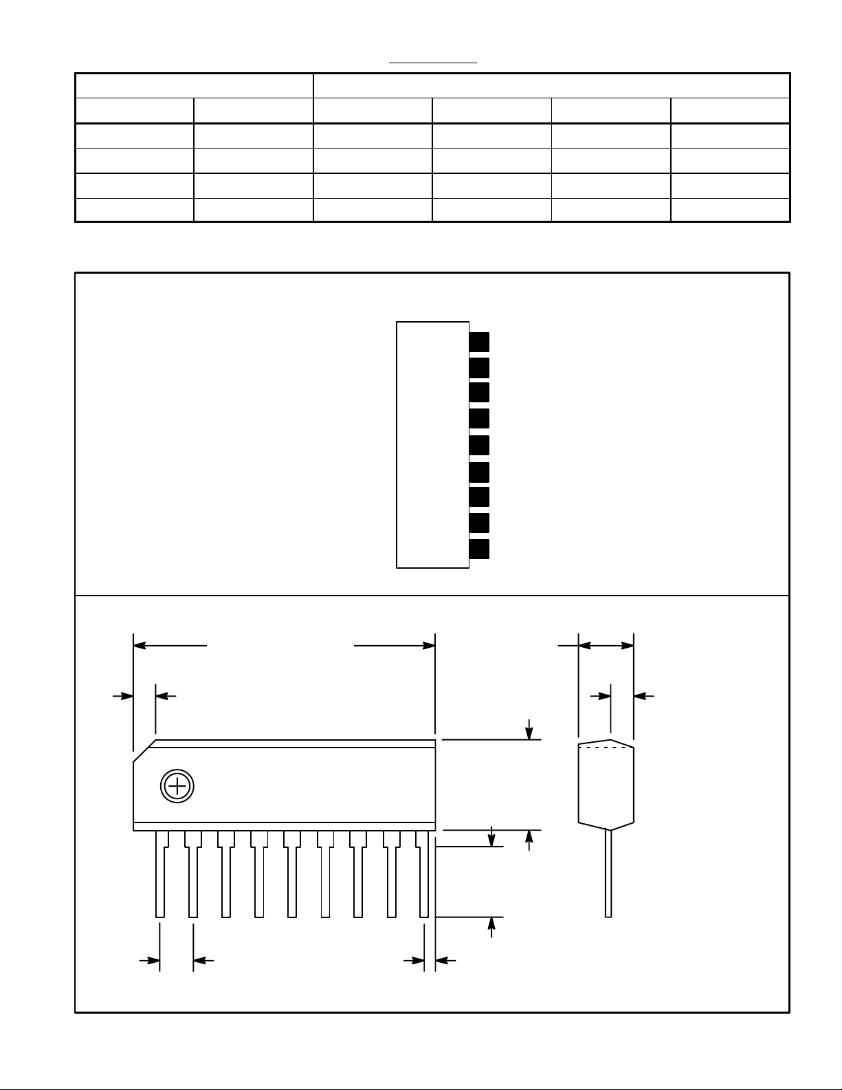
Input Output
Pin3 Pin4 Pin1 Pin2 Pin7 Pin8
L L H Z Z Z
H L Z H Z Z
L H Z Z H Z
H H Z Z Z H
Note 2. Z: High Impedance
Input Threshold Voltage: V
Truth Table
= 800mV, VTH = 3V
TL
.862 (21.89)
Pin Connection Diagram
(Front View)
9
V
Output 4
8
Output 3
7
V
6
GND
5
4
Input
Input
3
2
Output 2
Output 1
1
.118 (3.0)
CC
CC
1
2
.059 (1.5)
.053 (1.35)
.177
(4.5)
19
.110
(2.8)
.100 (2.54) .031 (0.78)
 Loading...