

NTE1655
Integrated Circuit
TV Stereo Decoder
Description:
The NTE1655 is a TV stereo decoder integrated circuit in a 16–Lead DIP type package designed for
television stereo. An L–R output is provided to drive further audio processing.
Features:
D Low Impedance L + R and L – R Outputs
D Mono/Stereo Switching and Indication
D Low Distortion – 0.10% typical
Applications:
D Stereo Television Sets
D Stereo Adapters
D Cable Television
Absolute Maximum Ratings
: (TA = +25°C unless otherwise specified)
Power Supply Voltage 16V. . . . . . . . . . . . . . . . . . . . . . . . . . . . . . . . . . . . . . . . . . . . . . . . . . . . . . . . . . . . . .
Power Dissipation 1800mW. . . . . . . . . . . . . . . . . . . . . . . . . . . . . . . . . . . . . . . . . . . . . . . . . . . . . . . . . . . . .
Derate Above 25°C 15mW/°C. . . . . . . . . . . . . . . . . . . . . . . . . . . . . . . . . . . . . . . . . . . . . . . . . . . . . .
Operating Ambient Temperature Range –40° to +85°C. . . . . . . . . . . . . . . . . . . . . . . . . . . . . . . . . . . . . .
Storage Temperature Range –65° to +150°C. . . . . . . . . . . . . . . . . . . . . . . . . . . . . . . . . . . . . . . . . . . . . . .
Lamp Drive Voltage Max Voltage at Pin7 with Lamp “Off” 16V. . . . . . . . . . . . . . . . . . . . . . . . . . . . . . . .
Lamp Current 100mA. . . . . . . . . . . . . . . . . . . . . . . . . . . . . . . . . . . . . . . . . . . . . . . . . . . . . . . . . . . . . . . . . . .
Electrical Characteristics
Parameter Test Conditions Min Typ Max Unit
DC (VIN = 0)
Supply Current VCC = 16V 15.0 33.5 50.0 mA
Output Voltage Pin4 1.7 3.5 5.0 V
Output Impedance Pin4, Pin5 – 100 300 W
Lamp Leakage Lamp OFF, Pin7 Voltage = 16V – – 0.1 mA
Lamp Saturation Voltage Lamp ON, Pin7 Current = 100mA – – 2.0 V
: (TA = +25°C, VCC = 12V unless otherwise specified)
Pin5 1.7 3.8 5.0 V
Electrical Characteristics (Cont’d): (TA = +25°C, VCC = 12V unless otherwise specified)
Parameter Test Conditions Min Typ Max Unit
Audio (Composite signal with 38kHzsubcarrier and 10% 19kHz pilot, f
L + R Channel Gain VIN = 2.5V
L + R Channel THD VIN = 2.5V
Gain Ratio, L + R Channel to L – R Channel VIN = 2.5V
Supply Rejection 100mV
DC Output Shift, Mono–to–Stereo Pilot OFF to ON, Pin4, Pin5 – – ±20 mV
Input Impedance Pin1 15 50 150 k
PLL
Pilot Level for Lamp ON 12 – 20 mV
Pilot Level for Lamp OFF 3 – 10 mV
Capture Range Pilot = 25mV
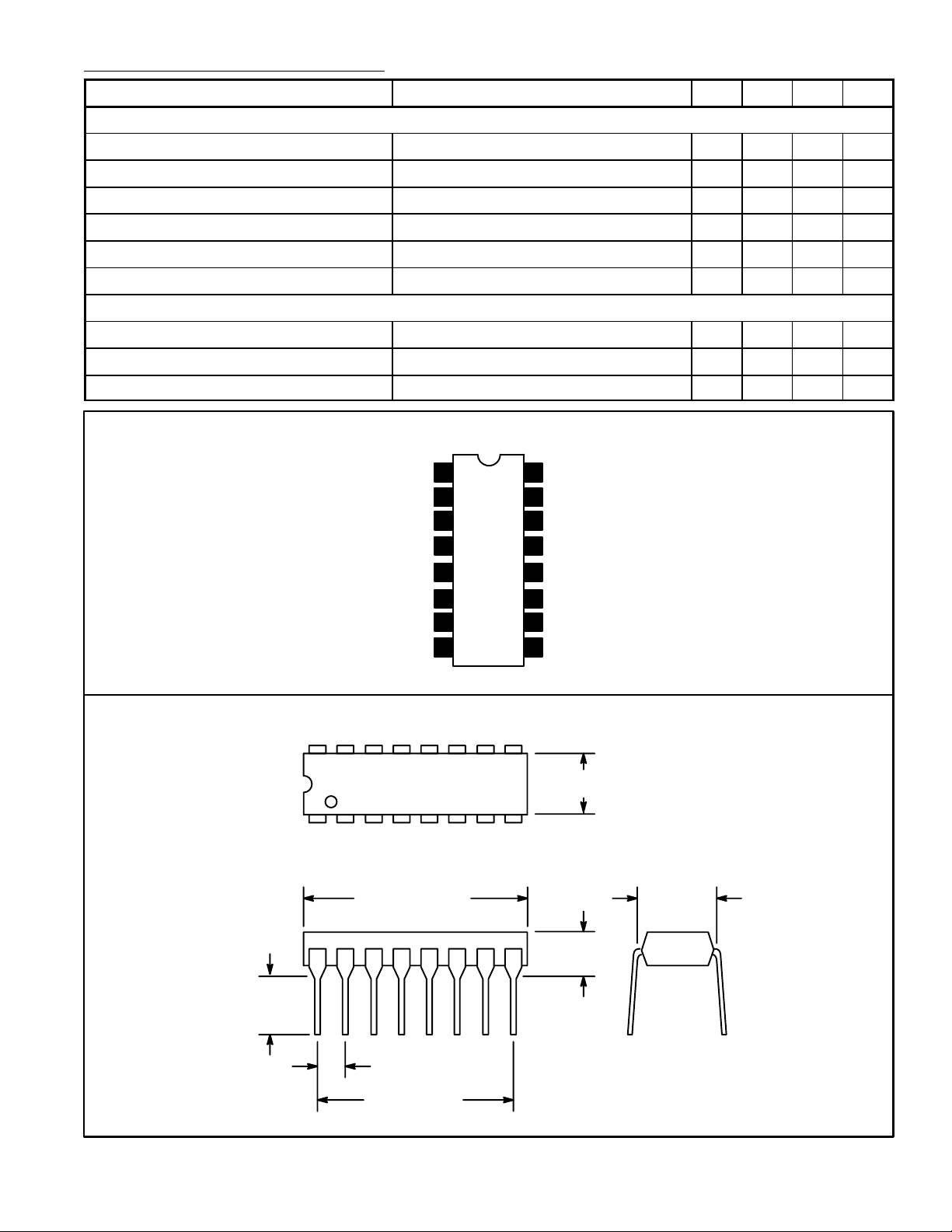
Pin Connection Diagram
Composite Input
0.0082µF to Pin12
L + R Feedback
L + R Input
L – R Feedback
rms
1
2
3
4
5
L = R, Pilot OFF, Pin4 0.8 1.0 1.2
P–P
L = R, Pilot OFF, Pin4 – 0.1 1.0 %
P–P
, L Only –2.0 0.0 2.0 dB
P–P
, 1kHz ON Supply, VIN = 0 30 60 – dB
rms
16
V
15
VCO Adjust
Phase Detector Filter
14
Phase Detector Filter
13
12
To Pin2
= 1kHz. Adjust P1 for 19kHz ±10Hz.
mod
±0.5 – – %
CC
L – R Output
Stereo Indicator LED
GND
16 9
18
.785 (19.9)
Max
.245
(6.22)
Min
6
7
8
15.734kHz Monitor
11
Stereo/Mono Switch
10
Stereo/Mono Switch
9
.260 (6.6) Max
.200 (5.08)
Max
.300
(7.62)
.100 (2.54)
.700 (17.7)
 Loading...