

NTE NTE1650 Datasheet
NTE1650
Integrated Circuit
w
Color TV Luminance–Chroma System
Absolute Maximum Ratings: (TA = +25°C unless otherwise specified)
Supply Voltage, V
Power Dissipation (T
Operating Temperature Range, T
Storage Temperature Range, T
Electrical Characteristics:
CC
= +65°C), P
A
Parameter Symbol Test Conditions Min Typ Max Unit
d
opr
stg
/Auto Flesh
15V. . . . . . . . . . . . . . . . . . . . . . . . . . . . . . . . . . . . . . . . . . . . . . . . . . . . . . . . . . . . . . . .
850mW. . . . . . . . . . . . . . . . . . . . . . . . . . . . . . . . . . . . . . . . . . . . . . .
–20° to +65°C. . . . . . . . . . . . . . . . . . . . . . . . . . . . . . . . . . . . . . . . .
–55° to +125°C. . . . . . . . . . . . . . . . . . . . . . . . . . . . . . . . . . . . . . . . . .
Maximum Chroma Output E
ACC Range E
Killer Sensitivity E
Color Recovery Conversion Benefit G
Relative Demodulation Angle é(R–Y)–é(B–Y) 100 115 130 deg.
Color Recovery Output Voltage E
Video Amplifier Benefit G
Video Amplifier Frequency Response f
Direct Current Reproduction Rate – 75 – %
Blanking Output Voltage 10.1 11.1 – V
Cmax
a
k
R–Y
E
B–Y/ER–Y
E
G–Y/ER–Y
é(G–Y)–é(B–Y) 240 255 270 deg.
O(DC)
∆E
O(DC)
V
G
VIR
C
Chroma Input B/C = 1/1,
P–P
= 0dB
100mV
Input = –20dB 0.40 0.53 0.76 V
0.50 0.65 0.80 V
–55 –40 –30 dB
6.2 7.8 – times
0.70 0.80 0.95 times
0.22 0.30 0.38 times
6.4 7.0 7.6 V
–0.3 – +0.3 V
9.2 11.0 12.8 times
3.5 4.5 5.2 times
5 – – MHz
P–P
P–P
Pin Connection Diagram
ACC Detector
Color Control
Killer Detector
st
1
BPA
2nd BPA
GND
Sync Pulse Input
VCO Filter
OSC Input
OSC Output
APC Control
DC Tint
Tint Adjust
Auto Flesh ON/OFF Switch
1
2
3
4
5
6
7
8
9
10
11
12
13
14
Peaking Capacitor
28
27
Video Input
26
Contrast/Color Adjust
Pedestal Clamp
25
24
VIR Output
Brightness Control
23
22
Blanking Input
21 Video Output
20
V
CC
19
Color Control Output
18
B–Y Demod Input
B–Y Output
17
16
R–Y Output
15
G–Y Output
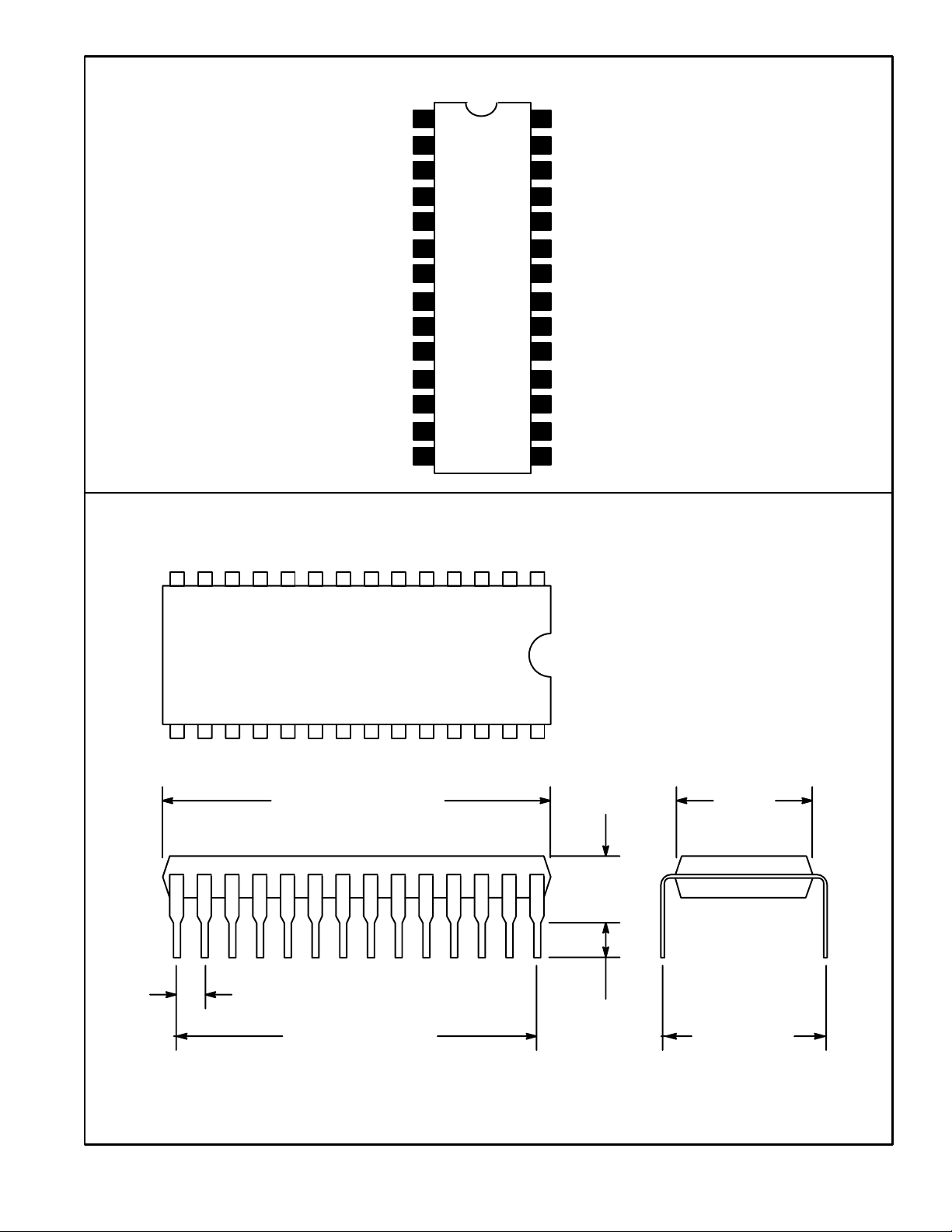
14 1
15 28
1.469 (37.32)
Max
.100 (2.54)
1.300 (33.02)
.250
(6.35)
.122
(3.1)
Min
.540
(13.7)
.600
(15.24)
 Loading...