

NTE NTE1648, NTE1649 Datasheet

NTE1648 and NTE1649
Integrated Circuit
Telephone Tone Ringer
Description:
The NTE1648 and NTE1649 are bipolar integrated circuits in an 8–Lead DIP type package designed
for telephone bell replacement.
Functions:
D Two Oscillators
D Output Amplifier
D Power Supply Control Circuit
Features:
D Designed for Telephone Bell Replacement
D Low Current Drain
D Small Size 8–Lead MINIDIP Package
D Adjustable 2–Frequency Tone
D Adjustable Warbling Rate
D Built–in Hysteresis Prevents False Triggering and Rotary Dial “CHIRPS”
D Extension Tone Ringer Modules
D Alarms or Other Altering Devices
D External Triggering or Ringer Disable (NTE1648)
D Adjustable for Reduced Supply Initiation Current (NTE1649)
Absolute Maximum Ratings:
Supply Voltage, V
Power Dissipation, P
Operating Temperature Range, T
Storage Temperature Range, T
CC
D
(TA = +25°C unless otherwise specified)
stg
opr
30V. . . . . . . . . . . . . . . . . . . . . . . . . . . . . . . . . . . . . . . . . . . . . . . . . . . . . . . . . . . . . . . .
400mW. . . . . . . . . . . . . . . . . . . . . . . . . . . . . . . . . . . . . . . . . . . . . . . . . . . . . . . . . .
–45° to +65°C. . . . . . . . . . . . . . . . . . . . . . . . . . . . . . . . . . . . . . . . .
–65° to +150°C. . . . . . . . . . . . . . . . . . . . . . . . . . . . . . . . . . . . . . . . . .
Electrical Characteristics: (TA = +25°C, All voltage referenced to GND unless otherwise specified)
Parameter Symbol Test Conditions Min Typ Max Unit
Operating Supply Voltage V
Initiation Supply Voltage V
Initiation Supply Current I
Sustaining Voltage V
Sustaining Current I
Trigger Voltage V
Trigger Current I
CC
SI
SI
SUS
SUS
TR
TR
Note 1 17 19 21 V
NTE1649–6.8k–Pin2 to GND, Note 1 1.4 2.5 4.2 mA
Note 2 9.7 11.0 12.0 V
No Load, VCC = V
, Note 2 0.7 1.4 2.5 mA
SUS
NTE1648 ONLY, VCC = 15V, Note 3 9.0 10.5 12.0 V
NTE1648 ONLY, Note 3 – 20.0 1000
– – 29 V
µA
Note 5
Disable Voltage V
Disable Current I
Output Voltage High V
DIS
DIS
OH
NTE1648 ONLY, Note 4 – – 0.5 V
NTE1648 ONLY, Note 4 –40 –50 – µA
VCC = 21V, I8 = –15mA,
17 19 21 V
Pin6 = 6V, Pin7 = GND
Output Voltage Low V
OL
VCC = 21V, I8 = 15mA,
– – 1.6 V
Pin6 = 6V, Pin7 = GND
Sink Current IIN (Pin3) Pin3 = 6V, Pin4 = GND – – 500 nA
IIN (Pin7) Pin7 = 6V, Pin6 = GND – – 500 nA
High Frequency f
Low Frequency f
H1
f
H2
L
R3 = 191k, C3 = 6800pf 461 512 563 H
R3 = 191k, C3 = 6800pf 576 640 704 H
R2 = 165k, C2 = 0.47µf 9 10 11 H
Z
Z
Z
Note 1. Initiation supply voltage (VSI) is the supply voltage required to start the tone ringer oscillating.
Note 2. Sustaining voltage (V
Note 3. V
Note 4. V
and ITR are the conditions applied to trigger in to start oscillation for V
TR
DIS
and I
are the conditions applied to trigger in to inhibit oscillation for VSI ≤ VCC.
DIS
) is the supply voltage required to maintain oscillation.
SUS
≤ VCC ≤ VSI.
SUS
Note 5. Trigger current must be limited to this value externally.
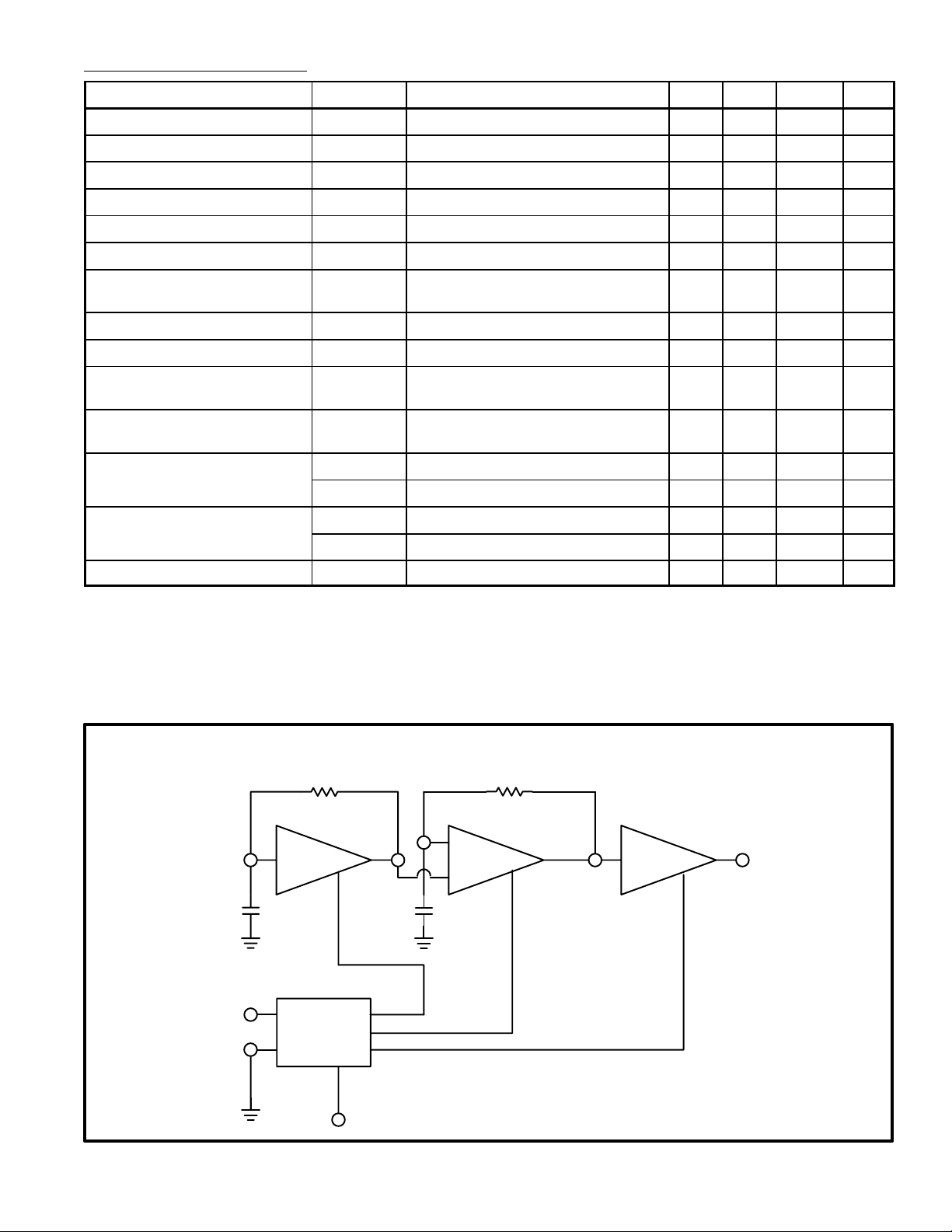
Pin Connection Diagram (NTE1648)
R1 R2
Low
3
Freq
OSC
C1 C2
1
5
Input
Power
Supply
with
Hysteresis
7
4
High
Freq
6
Amp
OSC
NOTE: C1, C2, R1, and
R2 are external parts
Output
8
2
Trigger Input
 Loading...