

NTE NTE1616 Datasheet
NTE1616
Integrated Circuit
TV Sound IF Amp/Detector, Driver
Description:
The NTE1616 is a TV sound integrated circuit in a 14–Lead DIP type package that can be operated
with no adjustment, using ceramic filters externally . This device contains a DC controlled attenuator,
which has wide effective area and gentle characteristic in the changing, so it is convenient especially
for a remote controlled set.
Features:
D Gentle Changing DC Controlled Attenuator is Convenient for Remote Controlled Sets.
D Operation with Ceramic Filters makes TV Sound Circuit No Adjustment Completely
D SRPP Output Circuit can be Driven Directly
D Muting Works Quickly
D Low Distortion Demodulation
Absolute Maximum Ratings: (TA = +25°C unless otherwise specified)
Power Supply Voltage, V
Voltage (Pin13, Pin14), V13, V
Output Current (Pin2), I
CC
14
2
Power Dissipation (TA = 75°C), P
Operating Temperature Range, T
Storage Temperature Range, T
stg
D
opr
–20° to +75°C. . . . . . . . . . . . . . . . . . . . . . . . . . . . . . . . . . . . . . . . .
–40° to +125°C. . . . . . . . . . . . . . . . . . . . . . . . . . . . . . . . . . . . . . . . . .
0 to 15V. . . . . . . . . . . . . . . . . . . . . . . . . . . . . . . . . . . . . . . . . . . . . . . . . . . . . .
0 to 15V. . . . . . . . . . . . . . . . . . . . . . . . . . . . . . . . . . . . . . . . . . . . . . . . . .
0 to 20mA. . . . . . . . . . . . . . . . . . . . . . . . . . . . . . . . . . . . . . . . . . . . . . . . . . . . . .
350mW. . . . . . . . . . . . . . . . . . . . . . . . . . . . . . . . . . . . . . . . . . . . . . . . .
Electrical Characteristics: (VCC = 12V, TA = +25°C ±3°C f = 4.5mHz, ∆f = ±25kHz, fM = 400Hz,
AM MOD = 30% unless otherwise specified)
Parameter Symbol Test Conditions Min Typ Max Unit
Total Supply Current I
IF Limiting Voltage V
Detector Output Voltage V
Detector Output Distortion THD
AM Rejection AMR Vi ≥ 3mV
DC VR Maximum Attenutation ATT
DC VR Distortion THD
CC
i(lim)
O AF
VCC = 12V Zero Carrier 15 20 25 mA
–3dB point – 200 400 µV
Vi = 10mV
DETVi
VRfin
VRfin
rms
= 10mV
= 400Hz, Vi = 600mV
= 400Hz, Vi = 600mV
rms
rms
rms
rms V8
450 600 750 mV
– 0.4 1.0 %
–44 –55 – dB
70 80 – dB
– 0.4 1.0 %
rms
rms
Electrical Characteristics (Cont’d): (VCC = 12V, TA = +25°C ±3°C f = 4.5mHz, ∆f = ±25kHz,
fM = 400Hz, AM MOD = 30% unless otherwise specified)
Parameter Symbol Test Conditions Min Typ Max Unit
AF Voltage Gain G
IF Input Resistance R
IF Input Capacitance C
Pin4 Input Resistance R
Pin4 Input Capacitance C
AF Output
Feedback
Attenuator Input
Detector Output
VAF
in
in
in4
in4
fin = 400Hz, Vi = 100mV
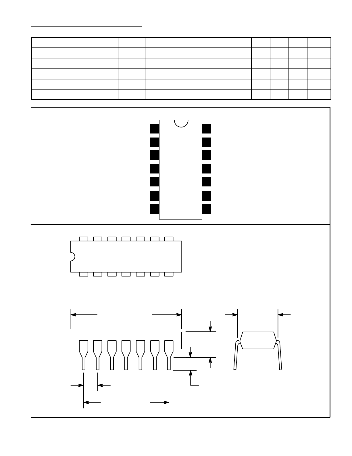
Pin Connection Diagram
CC
1
V
2
3
4
5
6Muting
7GND
, R3 = 1kΩ 11.5 15.0 – dB
rms
– 1.5 – kΩ
– 2.0 – pF
– 20 – kΩ
– 2.9 – pF
14
(+) IF Amp Input
13
(–) IF Amp Input
12
Low Pass Capacitor
11
Regulated Voltage
10
Discriminator
9 Discriminator
8
DC Attenuator
14 8
17
.785 (19.95)
.300 (7.62)
Max
.200
(5.08)
Max
.100 (2.45)
.099 (2.5) Min
.600 (15.24)
 Loading...