

NTE NTE1615 Datasheet
NTE1615
Integrated Circuit
B/W TV Tuner Bandswitch Circuit
Description:
The NTE1615 is an integrated circuit in a 9–Lead SIP type package designed for use as a B/W TV
tuner bandswitch circuit.
Features:
D Continuous VHF Band Tuning without High and Low Band Switching Operation
D Low Drain Current from Tuning Reference Voltage Supply
D High Breakdown Voltage Process
Absolute Maximum Ratings: (TA = +25°C unless otherwise specified)
Supply Voltage, V
Supply Current, I
Supply Current, I
Supply Current, I
Supply Current, I
Power Dissipation, P
CC
1
6
8
2
D
Operating Ambient Temperature Range, T
Storage Temperatuere Range, T
stg
opr
–20° to +70°C. . . . . . . . . . . . . . . . . . . . . . . . . . . . . . . . . .
–40° to +150°C. . . . . . . . . . . . . . . . . . . . . . . . . . . . . . . . . . . . . . . . .
36V. . . . . . . . . . . . . . . . . . . . . . . . . . . . . . . . . . . . . . . . . . . . . . . . . . . . . . . . . . . . . . . .
–10mA. . . . . . . . . . . . . . . . . . . . . . . . . . . . . . . . . . . . . . . . . . . . . . . . . . . . . . . . . . . . . . .
–25mA. . . . . . . . . . . . . . . . . . . . . . . . . . . . . . . . . . . . . . . . . . . . . . . . . . . . . . . . . . . . . . .
–10mA. . . . . . . . . . . . . . . . . . . . . . . . . . . . . . . . . . . . . . . . . . . . . . . . . . . . . . . . . . . . . . .
+20mA. . . . . . . . . . . . . . . . . . . . . . . . . . . . . . . . . . . . . . . . . . . . . . . . . . . . . . . . . . . . . . .
300mW. . . . . . . . . . . . . . . . . . . . . . . . . . . . . . . . . . . . . . . . . . . . . . . . . . . . . . . . . . .
Note 1. + and – are flow–in and flow–out current to/from the circuit respectively.
Electrical Characteristics: (TA = +25°C unless otherwise specified)
Parameter Symbol Test Conditions Min Typ Max Unit
Circuit Current I
Circuit Voltage V
V
V
V
I
9–1
9–8
2–5
4–6
V3 = 16V 1.0 1.5 2.0 mA
9
V3 = 16V 11 14 17 mA
4
V3 = 14V – – 1.5
V3 = 14V – – 1.5
V3 = 16V – – 0.3
V3 = 16V – – 1.2 V
V
V
V
Pin Connection Diagram
(Front View)
Input for Regulator
9
VHF (High) Band Place
8
VHF High/Low Reference
7
6
VHF High/Low Switch
GND
5
4
Voltage for Tuner
Tuning Voltage
3
VHF (Low) Band Place
2
UHF/VHF Band Place
1
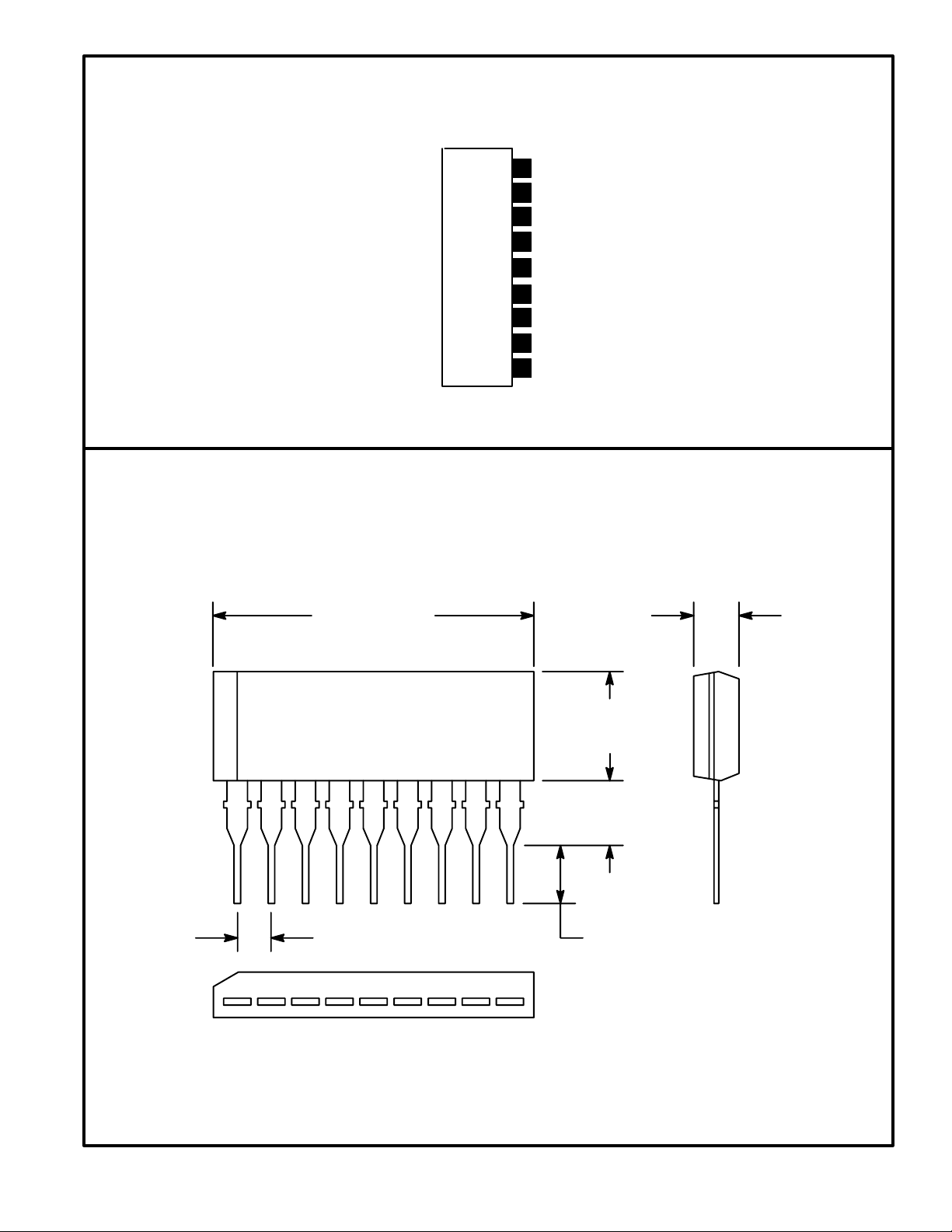
.929 (23.6) .118 (3.0)
.236
(6.0)
19
.098
(2.5)
.100 (2.54) .118(3.0)
 Loading...