

NTE NTE1608 Datasheet

NTE1608
Integrated Circuit
AM Tuner w/Electronic Tuning
Description:
The NTE1608 is a high performance integrated circuit in a 20–Lead DIP type package to be used as
an AM electronic tuner. It provides an automatic search–stop signal, local oscillator buffer–output,
and the low level local oscillation, as well as providing all other functions required of an AM tuner.
Moreover, the stable local oscillation from LW to SW facilities the use of many bands.
Functions:
D RF Amplifier
D IF Amplifier
D MIX
D AGC
D OSC (with ALC)
D Detection
D Local Oscillation Buffer–Output
D Signal Meter Driving Output (also used as an Automatic Search Stop–Signal).
Features:
D Narrow–Band Signal Meter: Available as an automatic search–stop signal (also available as
a wide–band signal meter). Signal meter output = 1/2 frequency ± 1.5kHz typ.
D Local Oscillation Buffer–Output:: Facilitates the design of electronic tuning systems and
frequency representation.
D OSC (with ALC): The oscillation output has been stabilized at a low level (350mV
varactor diode, and tracking error has been minimized.
D RF Amplifier: Excellent in usable sensitivity by incorporating low–noise transistors in cascode circuit
(45dB/m typ)
D MIX: Double balanced differential MIX prevents the influence of spurious radiation and IF
interferences (IF interference = 85dB typ)
D Low Noise: Excellent in S/N for intermediate input (57dB typ).
D Compensation for VCC Fluctuation: Allows little gain fluctuation and little distortion fluctuation
(8 to 16V).
D Low Shock Noise: Able to decrease the shock noise by selecting AGC time constant when
changing VCC–on and/or switching the mode.
rms
) for a
Electrical Characteristics: (TA = +25°C unless otherwise specified)
Supply Voltage (Pin8, Pin14), VCCmax 16V. . . . . . . . . . . . . . . . . . . . . . . . . . . . . . . . . . . . . . . . . . . . . . . .
Output Voltage (Pin5, Pin7), V
Input Voltage (Pin3), V
i
Supply Current (Pin5 + Pin7 + Pin8 + Pin14), I
Output High Drive Current (Pin18), I
Output High Drive Current (Pin20), I
o
max 32mA. . . . . . . . . . . . . . . . . . . . . . . . . . . . . . . . .
CC
18
20
Allowable Power Dissipation, PDmax 700mW. . . . . . . . . . . . . . . . . . . . . . . . . . . . . . . . . . . . . . . . . . . . . .
Operating Temperature Range, T
Storage Temperature Range, T
stg
opr
–20° to +70°C. . . . . . . . . . . . . . . . . . . . . . . . . . . . . . . . . . . . . . . . .
–40° to +125°C. . . . . . . . . . . . . . . . . . . . . . . . . . . . . . . . . . . . . . . . . .
Recommended Operating Condition: (TA = +25°C unless otherwise specified)
Recommended Supply Voltage, V
CC
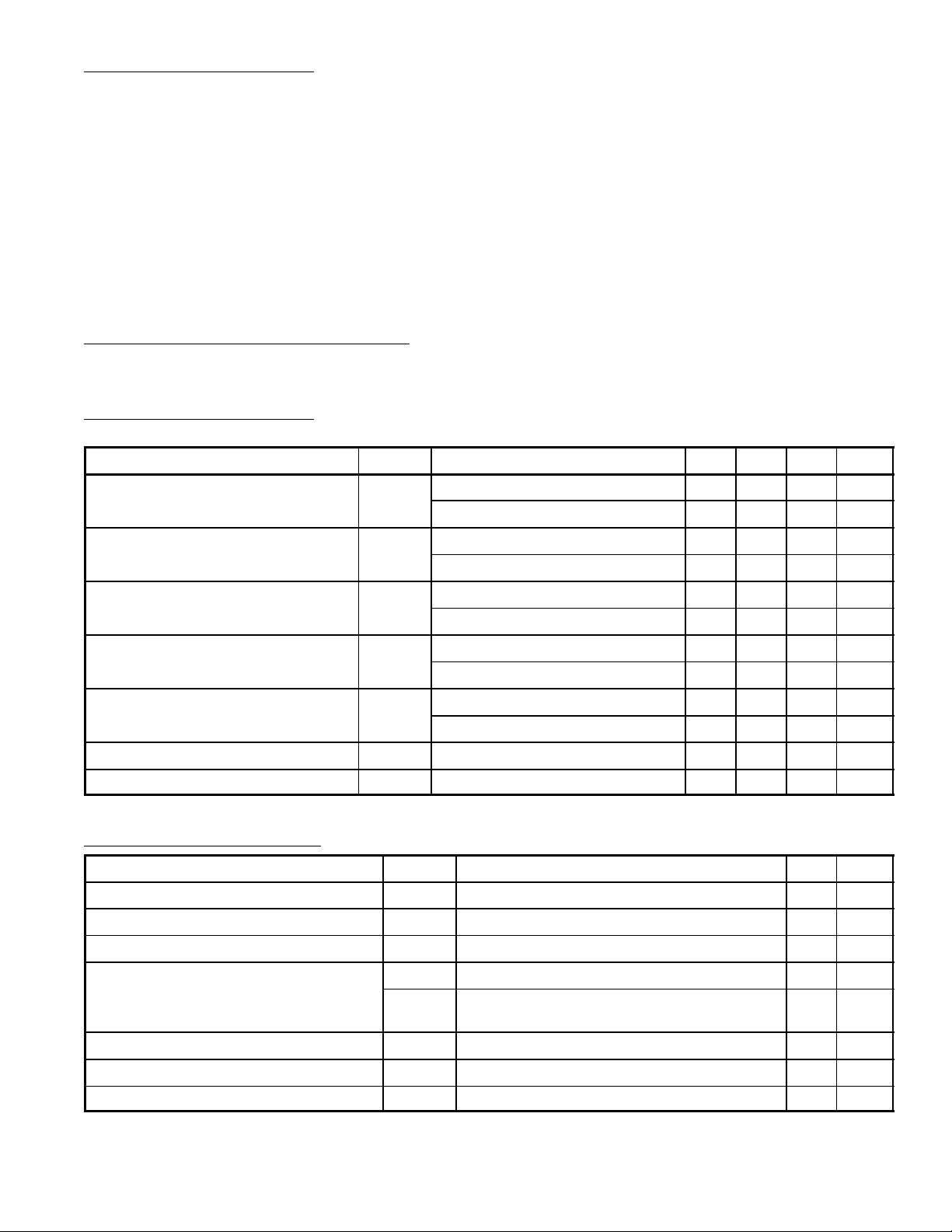
Electrical Characteristics: (TA = +25°C, VCC = 12V, fr = 1MHz, fm = 400Hz unless otherwise
specified)
Parameter Symbol Test Conditions Min Typ Max Unit
24V. . . . . . . . . . . . . . . . . . . . . . . . . . . . . . . . . . . . . . . . . . . . . . . . . . . . . .
5.6V. . . . . . . . . . . . . . . . . . . . . . . . . . . . . . . . . . . . . . . . . . . . . . . . . . . . . . . . . . . . .
5mA. . . . . . . . . . . . . . . . . . . . . . . . . . . . . . . . . . . . . . . . . . . . . . .
2mA. . . . . . . . . . . . . . . . . . . . . . . . . . . . . . . . . . . . . . . . . . . . . . .
12V. . . . . . . . . . . . . . . . . . . . . . . . . . . . . . . . . . . . . . . . . . . . . . . . . .
Current Dissipation I
Detector Output v
Signal–to–Noise Ratio S/N With 23dBµ Input, MOD = 30% 16 20 – dB
Total Harmonic Distortion THD With 80dBµ Input, MOD = 30% – 0.4 1.0 %
Signal Meter Output V
Input at Signal Meter Output = 1V V
Local Oscillation–Buffer Output V
CC
SM
OSC
Quiescent 16 25 35 mA
With 107dBµ Input 19 29 40 mA
With 23dBµ Input, MOD = 30% –27.5 –23.0 –18.5 dBm
o
With 80dBµ Input, MOD = 30% –15.5 –12.5 –9.5 dBm
With 80dBµ Input, MOD = 30% 52 57 – dB
With 107dBµ Input, MOD = 30% – 0.3 1.0 %
Quiescent – 0 0.5 V
With 107dBµ Input 3.0 4.5 7.0 V
in
19 25 31 dBµ
250 350 – mV
Reference Characteristics:
Parameter Symbol Test Conditions Typ Unit
Signal Meter Output V
Total Harmonic Distortion THD With 112dBµ Input, MOD = 30% 2 %
SM
With 40dBµ Input 2.5 V
rms
Local Oscillation Fluctuation within a Band DV
Signal Meter Bandwidth (Note 1)
Selectivity ±10kHz at 30% MOD 45 dB
IF Interference fr = 600kHz 85 dB
Image Frequency Interference Ratio fr = 1400kHz 40 dB
V
SM–BW
OSC
From V
With 80dBµ Input, 1/2 Output Frequency ±1.5 kHz
With 80dBµ Input, 1/10 Output Frequency –4.5
(522kHz) to V
OSC(L)
(1647kHz) 10 mV
OSC(H)
kHz
+7.0
rms
Note 1. BFB450C4 (Murata, japan) was used as a narrow band filter (0dBm = 775mV, 0dBµ = 1µV).
 Loading...