

NTE NTE1604 Datasheet

NTE1604
Integrated Circuit
FM IF System for Car Radio
Description:
The NTE1604 is an integrated circuit in a 16–Lead SIP type package designed for use in FM car stereo
receivers. T his d evic e features v ers atile m uting c har acterist ics a nd a llow s r eceiver d e signers t o realize
the muting performance according to their design concept.
Functions:
D IF Amplification/Limiter
D AFC Output
D Muting Bandwidth
D Quadrature Detector
Features:
D Versatile Mutings
a. When Muting Operation is Performed under a Weak Signal Strength, an Attenuation Slope
of the Audio Output Against the Input Signal Strength Varaitions can be Set at any Given
value
b. Maximum Muting Attenuation can be Selected Between about 6dB to 40dB
c. Input Signal Strength level which Actuates the Muting Circuit can be Set Freely
D High Limiting Sensitivity (25dbµ Typ. with Muting OFF) Provides a Fine Quieting Characteristic
D High Signal–to–Noise Ratio: 78dB Typ
D Low Distortion (0.05% Typ) Available, if used with Double–Tuned Circuits
D Good AM Rejection Ratio (63dB with 6 Stages of Differential IF Amplifiers)
D Signal Merter Drive Output Proportional to the Input Signal Strength in dB
D Clamped (±VBE) AFC Output, Bandwidth Adjustable
D Delayed AGC Output for Front End Circuit
D Signal Meter Output
D Muting Under Weak Signal Strength
D AF Preamplifier
D AGC Output
Absolute Maximum Ratings: (TA = +25°C unless otherwise specified)
Maximum Supply Voltage (Pin12), VCCmax 16V. . . . . . . . . . . . . . . . . . . . . . . . . . . . . . . . . . . . . . . . . . . .
Maximum Supply Current (Pin12), ICCmax 40mA. . . . . . . . . . . . . . . . . . . . . . . . . . . . . . . . . . . . . . . . . . .
Allowable Power Dissipation, PDmax
TA = +25°C 640mW. . . . . . . . . . . . . . . . . . . . . . . . . . . . . . . . . . . . . . . . . . . . . . . . . . . . . . . . . . . . . . .
TA = +70°C 460mW. . . . . . . . . . . . . . . . . . . . . . . . . . . . . . . . . . . . . . . . . . . . . . . . . . . . . . . . . . . . . . .
Input Voltage (Pin1 to Pin2), v
Flow–In Current (Pin2, Pin3), I2, I
Flow–In Current (Pin6), I
6
. . . . . . . . . . . . . . . . . . . . . . . . . . . . . . . . . . . . . . . . . . . . . . . . . . . .
i
3
Flow–Out Current (Pin5, Pin15, Pin16), I5, I15, I
Flow–Out Current (Pin13, Pin14), I13, I
Operating Temperature Range, T
Storage Temperature Range, T
stg
14
opr
16
–20° to +70°C. . . . . . . . . . . . . . . . . . . . . . . . . . . . . . . . . . . . . . . . .
–40° to +125°C. . . . . . . . . . . . . . . . . . . . . . . . . . . . . . . . . . . . . . . . . .
±1V
±0.2mA. . . . . . . . . . . . . . . . . . . . . . . . . . . . . . . . . . . . . . . . . . . . . . . . .
P–P
2mA. . . . . . . . . . . . . . . . . . . . . . . . . . . . . . . . . . . . . . . . . . . . . . . . . . . . . . . . . .
1mA. . . . . . . . . . . . . . . . . . . . . . . . . . . . . . . . . . . . .
2mA. . . . . . . . . . . . . . . . . . . . . . . . . . . . . . . . . . . . . . . . . . . . .
Recommended Operating Conditions: (TA = +25°C unless otherwise specified)
Recommended Supply Voltage, V
VCC Range on Operation, V
CC
CC
7.5V to 16V. . . . . . . . . . . . . . . . . . . . . . . . . . . . . . . . . . . . . . . . . . . . . . . .
Electrical Characteristics: (TA = +25°C, VCC = 8V, f = 10.7MHz unless otherwise specified)
Parameter Symbol Test Conditions Min Typ Max Unit
Quiescent Current I
Current Dissipation I
Demodulated Output v
CCO
CC
o
Total Harmonic Distortion THD vin = 100dBµ, 400Hz, 100% MOD – 0.05 0.2 %
Signal–to–Noise Ratio S/N vin = 100dBµ, 400Hz, 100% MOD 72 78 – dB
Input Limiting Voltage v
Muting Sensitivity v
i(lim)
i(mute)
Muting Attenuation Mute (ACC) V6 = 2V (22kΩ)
Muting Bandwidth BW (mute) vi = 100dBµ, V14 = 2V 140 210 370 kHz
AM Rejection Ratio AMR vi = 100dBµ, FM: 400Hz, 100% MOD,
Muting Drive Output V
Signal Meter Output V
AGC Output V
Offset Voltage V
V
14–100
V
15–50
V
15–70
V
15–100
V
16–100
V
14–0
15–0
16–0
7–13
8–13
Quiescent 15 21 27 mA
vin = 100dBµ 20 25 30 mA
vin = 100dBµ, 400Hz, 100% MOD 200 260 320 mV
vo: 3dB Down, 400Hz, 100% MOD – 25 29 dBµ
V14 = 2.0V 22 26 32 dBµ
10 15 20 dB
24 28 32 dB
V6 = 5V (22kΩ)
vi = 100dBµ, 400Hz,
100% MOD
50 63 – dB
AM: 1kHz, 30% MOD
Quiescent 3.5 4.2 5.0 V
vi = 100dBµ 0.0 0.0 0.3 V
Quiescent 0.0 0.1 0.3 V
vi = 50dBµ 0.8 1.4 2.0 V
vi = 70dBµ 1.6 2.4 3.2 V
vi = 100dBµ 4.5 5.3 6.0 V
Quiescent 3.5 4.1 4.5 V
vi = 100dBµ 0.0 0.02 0.3 V
Quiescent, Pin7 to Pin13 –0.25 0.0 +0.25 V
Quiescent, Pin8 to Pin13 –0.5 0.0 +0.5 V
8V. . . . . . . . . . . . . . . . . . . . . . . . . . . . . . . . . . . . . . . . . . . . . . . . . . .
rms
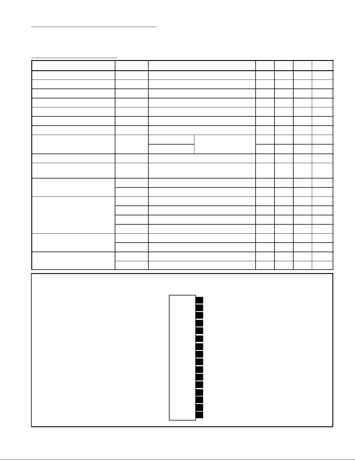
Pin Connection Diagram
(Front View)
AGC
16
15
“S” Meter
Mute Drive
14
13
V
ref
12
V
CC
11 Quad Input
GND
10
IF Output
9
AF Output
8
AFC
7
Mute Input6
5
Mute Attenuation Adjust
GND4
Bypass
3
Bypass
2
IF Input1
 Loading...