

NTE NTE1589 Datasheet
NTE1589
Integrated Circuit
Color TV Luminance Chroma System
Description:
The NTE1589 is a multi–operational integrated circuit in a 28–Lead DIP type package which has all
the necessary functions for video–chroma: such as second differential video tone control circuit (DC
controlling available), contrast control, pedestal clamp, brightness adjustment circuit, video blanking
circuit, BPA amplifier (peak detection shaped ACC detector), color synchronizer (APC type), and color
recovery (color difference output).
Characteristics:
D Because of its second differential video tone control method of current amplifying type, amplitude
of pre–shoot and over–shoot can be restrained, and sharp outline correction is available.
D ‘fo’ adjustment of V
D Because of its color difference output, frequency response of video amplifier is very good.
D Because its control is all D.C. controlling, remote control is available.
is available by variable resister
CO
Absolute Maximum Ratings
Power Supply Voltage, V
Power Consumption, P
D
: (TA = +25°C unless otherwise specified)
CC
Operating Temperature Range, T
Storage Temperature Range, T
stg
Electrical Characteristics:
Parameter Symbol Test Conditions Min Typ Max Unit
BPA Chroma Output E
ACC Range E
Killer Sensitivity E
Color Recovery Conversion
Benefit
Color Recovery Output Voltage E
opr
–55° to +125°C. . . . . . . . . . . . . . . . . . . . . . . . . . . . . . . . . . . . . . . . . .
e
a
k
G
r–y
E
b–y
E
r–y
E
g–y
O(DC)
burst: chroma = 1.1, burst = 100mV
burst: chroma = 1.1, burst = 10mV 0.30 0.55 0.74 V
burst 100mV
R–Y output 6.4 7.0 7.6 V
B–Y output/R–Y output 1.05 1.20 1.35 times
G–Y output/R–Y output
Angle (R–Y) – Angle (B–Y) = 105°
Non–signal input, VCO free–run 6.4 7.0 7.6 V
= 0dB – –44 – dB
p–p
p–p
0.54 0.67 0.85 V
0.30 0.40 0.50 times
15V. . . . . . . . . . . . . . . . . . . . . . . . . . . . . . . . . . . . . . . . . . . . . . . . . . . . . . . . . .
850mW. . . . . . . . . . . . . . . . . . . . . . . . . . . . . . . . . . . . . . . . . . . . . . . . . . . . . . . .
–15° to +65°C. . . . . . . . . . . . . . . . . . . . . . . . . . . . . . . . . . . . . . . . .
p–p
p–p
Electrical Characteristics (Cont’d):
Parameter Symbol Test Conditions Min Typ Max Unit
Color Recovery Output E
Operational DC Voltage
O(DC)
O(DC)
Non–signal input, VCO free–run –0.3 0 +0.3 V
(B–Y) – (R–Y)
(R–Y) – (G–Y)
(G–Y) – (B–Y)
Video Amplifier Benefit G
At terminal 22, V = 0,3V
V
p–p
,
10.5 12.0 13.5 times
f = 100kHz examined Pin19
Video Amplifier Frequency
f
Measured with –3dB, 0dB when f = 100kHz – 6.5 – MHz
e
Response
Direct Current Reproduction Rate – 75 – %
Blanking Output Voltage 11 – – V
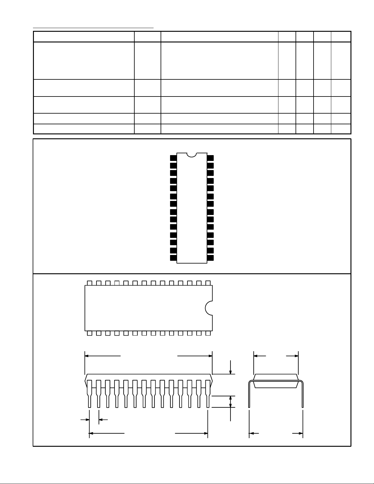
Pin Connection Diagram
GND
Video Input
1st BPA
Color/Contrast Control
Color Control Output
Killer Filter
Gate Pulse
VCO
Tint Control
VCO
VCO Output
APC Filter
Color Demod
1
2
3
4
5Color Control
6
7
8
9
11
12
13
14
AGC
28
Video Input
27
Tone Control
26
Video Tone Control
25
Tone Control
24
23
V
CC
Contrast Control
22
21 Pedestal Clamp
ABL
20
Video Output10
19
18
Blanking Pulse
B–Y Output
17
R–Y Output
16
15
G–Y Output
14 1
15 28
1.469 (37.32) Max
.100 (2.54)
1.300 (33.02)
.250
(6.35)
.122
(3.1)
Min
.540
(13.7)
.600
(15.24)
 Loading...