

NTE NTE1580 Datasheet
NTE1580
Integrated Circuit
IF Amp & Detector
Description:
The NTE1580 is an IF amplifier in a 14–Lead DIP type package with a symmetrical FM demodulator
and an AF amplifier with adjustable output voltage. The AF amplifier is also provided with an output
for volume control and an input for VCR operation.
The input and output of the NTE1580 are especially designed for LC–circuits, but the input can also
be used with a ceramic filter.
Absolute Maximum Ratings:
Maximum Supply voltage (Pin11, Note 1), Vp = V
Maximum Adjustment Voltage (Pin5), V
Maximum Total Power Dissipation, P
Bypass Resistance, R
13–14
Operating Ambient Temperature Range, T
Storage Temperature Range, T
stg
5–1
tot
A
11–1
Note 1. Supply voltage operating range is 10V to 18V
–15° to +70°C. . . . . . . . . . . . . . . . . . . . . . . . . . . . . . . . . . .
–40° to +125°C. . . . . . . . . . . . . . . . . . . . . . . . . . . . . . . . . . . . . . . . . .
18V. . . . . . . . . . . . . . . . . . . . . . . . . . . . . . . . . . .
6V. . . . . . . . . . . . . . . . . . . . . . . . . . . . . . . . . . . . . . . . . . . . . .
400mW. . . . . . . . . . . . . . . . . . . . . . . . . . . . . . . . . . . . . . . . . . . .
1kΩ. . . . . . . . . . . . . . . . . . . . . . . . . . . . . . . . . . . . . . . . . . . . . . . . . . . . . . . . . .
Electrical Characteristics
Parameter Symbol Test Conditions Min Typ Max Unit
IF Voltage Gain G
Input Voltage Starting Limiting V
IF Output Voltage at Limiting
(Peak–to–Peak)
AM Suppression α ∆f = ±50kHz, Vi = 500µV,
IF Residual Voltage Without De–Emphasis
Pin12
Pin8 V
AF Voltage Gain G
AF Adjustment ∆V
AF Output Voltage Control Range ∆V
Adjustment Resistor R
DC Voltage Portion at the AF Outputs
Pin12
Pin8 V
: (VP = 12V, TA = +25°C, f = 5.5MHz unless otherwise specified)
V IF6–14
V
O IF(p–p)
V
IF12
V AF8–3
O(AF)
O(AF)
4–5
V
12–1
8–1
IF8
∆f = ±50kHz, fm = 1kHz – 30 60 µV
i
f
= 1kHz, m = 30%
m
R
= 5kΩ, R
4–5
Note 2 1 to 10 kΩ
= 13kΩ 20 28 36 dB
5–1
– 68 – dB
– 250 – mV
50 60 – dB
– 30 – mV
– 20 – mV
– 7.5 –
70 85 – dB
– 5.6 – V
– 4.0 – V
Note 2. Pin5 must be connected to Pin4, when volume control adjustment is not applicable.
Electrical Characteristics (Cont’d): (VP = 12V, TA = +25°C, f = 5.5MHz unless otherwise specified)
Parameter Symbol Test Conditions Min Typ Max Unit
Output Resistance of the AF outputs
Pin12
Pin8 R
Input Resistance of the AF Input R
Stabilized Reference Voltage V
Source Resistance of Reference
Voltage Source
Hum Suppression
Pin12
Pin8 V8/V
Supply Current (Pin11) IP = I
IF Input Impedance |Zi| 4.5pF – 40 – kΩ
R
O12–1
O8–1
I3–1
= V
4–1
R
4–1
V12/V
ref
11
11
11
6.0pF 15 – – kΩ
– 1.1 – kΩ
– 1.1 – kΩ
– 2.0 – kΩ
4.2 4.8 5.3 V
– 12 – Ω
– 30 – dB
– 35 – dB
9.5 13.5 17.5 mA
AF Output Voltage
Pin12
Pin8
Distortion d
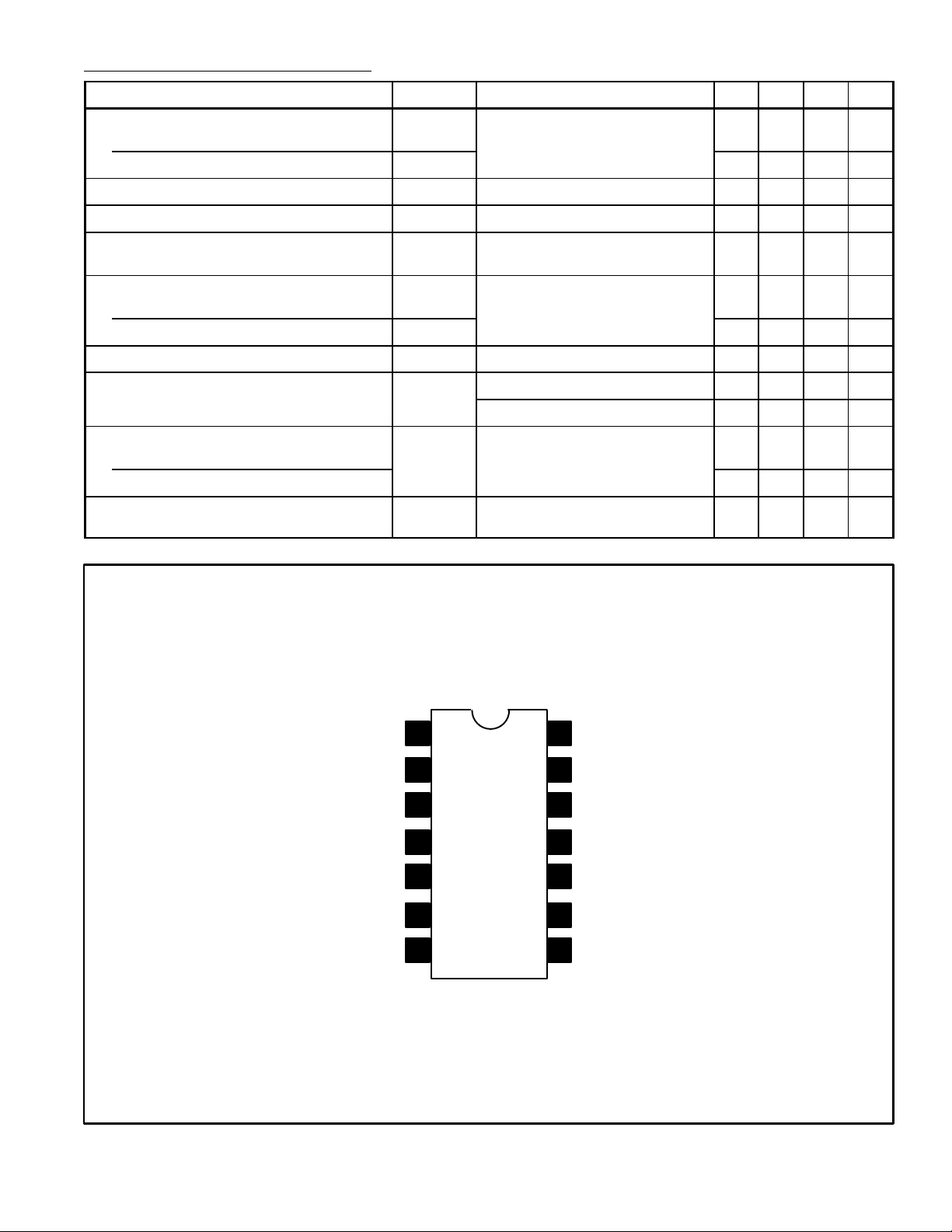
GND
Bias Decoupling
Recorder Audio Input
Volume Control Bias
V
OAF(rms)
Pin Connection Diagram
1
2
3
4
5Volume Control
∆f = ±50kHz, Vi = 10µV,
fm = 1kHz, QO = 45
tot
∆f = ±50kHz, Vi = 10µV,
f
= 1kHz, QO = 20
m
14
IF Input
IF Input Bias
13
Constant Level Audio Out
12
11
V
CC
– 1.0 – V
– 1.2 – V
– 1.0 – %
10 IF Amp Output
6IF Amp Output
7Phase Shift Network
9 Phase Shift Network
8
Volume Controlled Audio Output
 Loading...