

NTE NTE1578 Datasheet
NTE1578
Integrated Circuit
FM Mixer/IF Amp
Description:
The NTE1578 is an FM front–end integrated circuit in a 16–Lead DIP type package designed for use
in car radio and home stereo applications. This device has a built–in AGC driver circuit which improves interference characteristics. It thereby offers advantages such as improved interference characteristics without sacrificing usable sensitivity and the conventional DX–LOCAL change–over
switch.
Features:
D Double–Balanced Type MIX (Improved Spurious Characteristic)
D Keyed AGC/Keyed Classical AGC (Improved Intermodulation, Cross Modulation Characteristic)
D Differential IF Amplification (Improved Limiting Characteristic)
Absolute Maximum Ratings: (TA = +25°C unless otherwise specified)
Maximum Supply Voltage (Pin12, Pin15), V
Maximum Supply Voltage (Pin5, Pin6), V
CC2
Allowable Power Dissipation (TA ≤ +50°C, Note 1), PDmax 600mW. . . . . . . . . . . . . . . . . . . . . . . . . . . .
Operating Temperature Range, T
Storage Temperature Range, T
opg
stg
max 8.5V. . . . . . . . . . . . . . . . . . . . . . . . . . . . . . . . . . . .
CC1
max 16V. . . . . . . . . . . . . . . . . . . . . . . . . . . . . . . . . . . . . . .
–20° to +70°C. . . . . . . . . . . . . . . . . . . . . . . . . . . . . . . . . . . . . . . . .
–40° to +125°C. . . . . . . . . . . . . . . . . . . . . . . . . . . . . . . . . . . . . . . . . .
Note 1. PDmax = 460mW at TA = +70°C
Recommended Operation Condition: (TA = +25°C unless otherwise specified)
Recommended Supply Voltage (Pin12, Pin15), V
Recommended Supply Voltage (Pin5, Pin6), V
Electrical Characteristics: (TA = +25°C, V
Parameter Symbol Test Conditions Min Typ Max Unit
Dissipation Current
Local OSC Input Offset ∆V
MIX Input Offset ∆V
MIX Output Offset ∆I
High Level AGC Output V
Low Level AGC Output V
I
CC1
I
CC2
INOSC
INMIX
OUT MIX
AGC H
AGC L
Pin 12, 15 17 25 36 mA
Pin 5, 6 5 8 11 mA
Vi = 0dBu, VCL = 4V 7.6 7.9 – V
Vi = 100dB, VCL = 4V – 0.5 1 V
CC2
CC1
CC1
= 8V, V
= 13V unless otherwise specified)
CC2
–20 0 20 mV
–20 0 20 mV
–600 0 600 µA
8V. . . . . . . . . . . . . . . . . . . . . . . . . . . . . . . . . . . . .
13V. . . . . . . . . . . . . . . . . . . . . . . . . . . . . . . . . . . . . .
Electrical Characteristics (Cont’d): (TA = +25°C, V
Parameter Symbol Test Conditions Min Typ Max Unit
CC1
= 8V, V
= 13V unless otherwise specified)
CC2
AGC Control Input
IF Input Resistance R
Voltage Gain VG Vi = 62dBu 80 85 90 dBµ
Input Limiting Voltage V
AGC Input Voltage V
Saturation Output Voltage V
V
CL 7
V
CL 2
i lim
i AGC
OUT
IN
IF Input
IF Decoupling
GND
AGC Input
Mixer Output
Mixer Output
OSC Input
Vi = 100dBu, V
Vi = 100dBu, V
V
= 2V 62 71 80 dBµ
AGC
V
= 2V 62 71 80 dBµ
AGC
Vi = 100dBµ 91 95 – dBµ
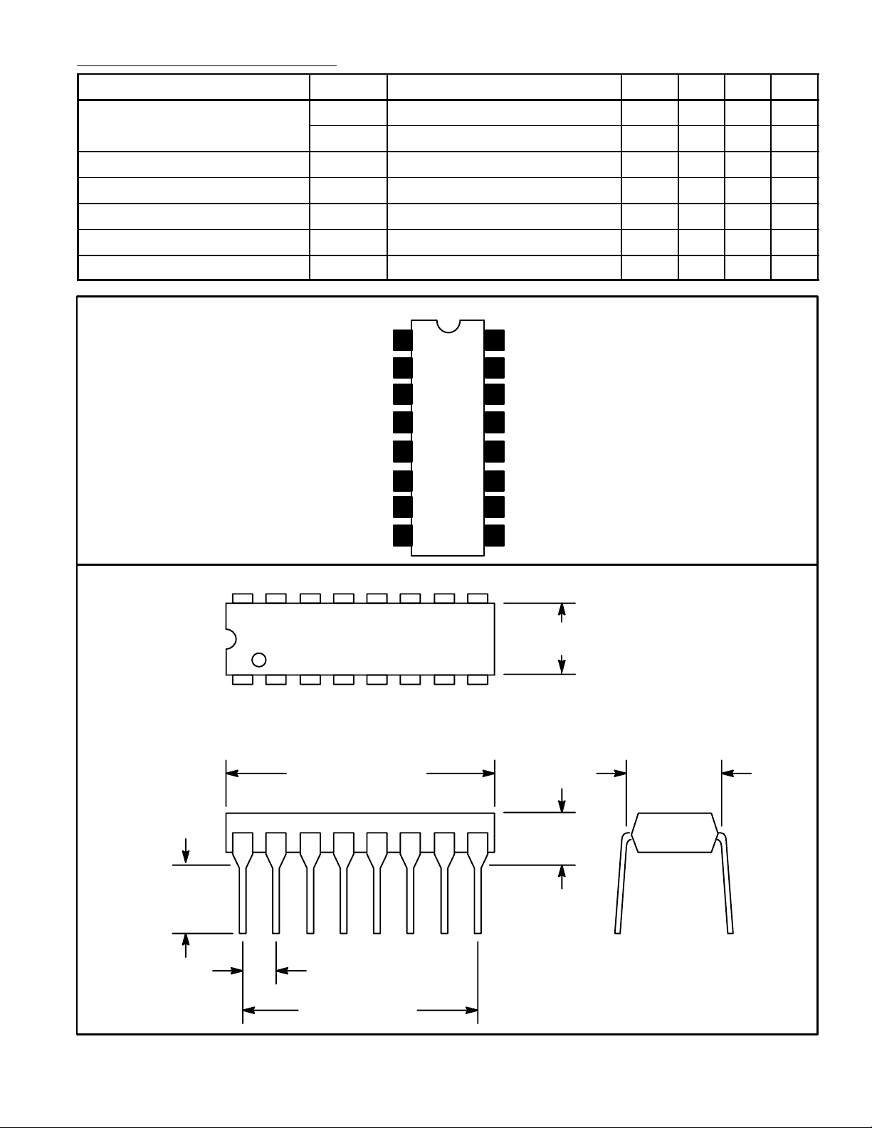
Pin Connection Diagram
1
2
3
4
5
6
7
= 7V – 0.35 0.6 V
AGC
= 2V 1.2 1.7 2.2 V
AGC
230 330 430 ohm
IF Output
16
15
V
CC
AGC Inhibit
14
AGC Output
13
12
V
CC
GND
11
RF Input
10
.245
(6.22)
Min
OSC Input
8
RF Input
9
16 9
.260 (6.6) Max
18
.785 (19.9)
Max
.300
(7.62)
.200 (5.08)
Max
.100 (2.54)
.700 (17.7)
 Loading...