

NTE NTE1576 Datasheet
NTE1576
Integrated Circuit
Dual Volume Control/Balance/Tone
Description:
The NTE1576 is a DC controlled dual volume, balance and tone (Bass, treble) integrated circuit in
1 16–Lead DIP type package. As these dual channels are constructed on one chip, this IC is excellent
in pair characterisitics and it is suitable for automobile stereo, radio cassette, music center, TV multiplex sound receiver and remote controlled applications.
Features:
D Wide Power Supply Voltage Range:
Single Supply VCC (opr) = 8V to 14V
Dual Supply VCC – VEE (opr) = ±4V to ±7V
D Wide Volume Control Range: VR = 80dB (Typ.)
D Excellent Cross Talk: CT = 70dB (Typ)
D Stable for Temperature Drift
D Wide Tone Control Range:
VB = 10dB (Typ) at f = 1kHz 100Hz
VT = 12dB (Typ) at f = 1kHz 20kHz
Absolute Maximum Ratings: (TA = +25°C unless otherwise specified)
Supply Voltage, V
Power Dissipation, P
CC
D
Derated above 25°C 6mW/°C. . . . . . . . . . . . . . . . . . . . . . . . . . . . . . . . . . . . . . . . . . . . . . . . . . . . . .
Operating Temperature Range, T
Storage Temperature Range, T
opr
stg
Electrical Characteristic: (TA = +25°C unless otherwise specified)
Parameter Symbol Test Conditions Min Typ Max Unit
Quiescent Current I
Maximum Input Voltage V
Maximum Output Voltage V
Voltage Gain G
CCQ
IN
OUT
V
VOL/BAL/BASS
SW
BASS/TRBL/BAL SW
VOL SW4: A, THD = 1%
BASS/TRBL/BAL SW
VIN = 0.1V
1 – 4
: B
, VOL SW4: A
rms
VCC, VEE = ±4V – 11 17 mA
: B,
1 – 3
: B
1 – 3
750mW. . . . . . . . . . . . . . . . . . . . . . . . . . . . . . . . . . . . . . . . . . . . . . . . . . . . . . . . . . .
–20° to +75°C. . . . . . . . . . . . . . . . . . . . . . . . . . . . . . . . . . . . . . . . .
–55° to +150°C. . . . . . . . . . . . . . . . . . . . . . . . . . . . . . . . . . . . . . . . . .
10 18 25 mA
– – 1 V
1 – – V
–0.5 2.0 4.5 dB
rms
rms
14V. . . . . . . . . . . . . . . . . . . . . . . . . . . . . . . . . . . . . . . . . . . . . . . . . . . . . . . . . . . . . . . .
Electrical Characteristic (Cont’d): (TA = +25°C unless otherwise specified)
Parameter Symbol Test Conditions Min Typ Max Unit
Channel Balance CB BASS/TRBL/BAL SW
VIN = 0.1V
VOL/BAL/BASS/TRBL SW
V
= 0.1V
IN
Volume Control Range V
Bass Control Range VB Max
VB Min
Treble Control Range VT Max
VT Min
Tone Error DG
Total Harmonic Distortion THD BASS/TRBL/BAL SW
Output Noise Voltage V
Crosstalk CT BASS/TRBL/BAL SW
Control Terminal Input
Resistance
R
BASS/TRBL/BAL SW
R
VOL SW4: A → C, VIN = 1V
VOL/BAL SW
VIN = 1V
f = 1kHz → 100Hz
VOL/BAL SW
VIN = 1V
f = 1kHz → 20kHz
VOL/BAL SW
V
BASS/TRBL SW
VOL SW4: A, VO = 150mV
BASS/TRBL/BAL SW
NO
VOL SW4: A, BPF = 50Hz to 20kHz,
Input Open
VOL SW4: A, V
Pin8, Pin9, Pin10 – 500 – kΩ
IN
Pin7 – 200 – kΩ
, VOL SW4: A
rms
, f = 100Hz to 20kHz
rms
: B,
3,4
rms,
: B,
3,4
rms,
: B, VIN = 1V
3,4
: C → A
1,2
OUT
: B
1 – 3
: B,
1 – 4
: B,
1 – 3
rms
BASS/TRBL SW
BASS/TRBL SW
BASS/TRBL SW
BASS/TRBL SW
,
rms
: B,
1 – 3
rms
: B,
1 – 3
: B,
1 – 3
= 1V
rms
–3 0 +3 dB
–3.5 0 +3.5 dB
70 80 – dB
: A 7 11 14 dB
1,2
: C –15.0 –11.5 –7.0 dB
1,2
: A 7 11 14 dB
1,2
: C –20 –14 –10 dB
1,2
– 6 10 dB
– 0.1 0.35 %
– 130 300 µV
– 70 – dB
rms
V
EE
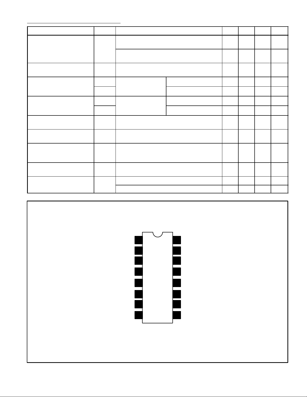
Ch 1 Input
Treble Freq Set 1
Bass Freq Set 1
Reference Control
Ch 1 Output
Balance Control
Volume Control
Pin Connection Diagram
1
2
3
4
5
6
7
8
16
15
14
13
12
11
10
9
Reference Signal
Ch 2 Input
Treble Freq Set 2
Bass Freq Set 2
V
CC
Ch 2 Output
Treble Control
Bass Control
 Loading...