

NTE NTE1559 Datasheet
Integrated Circuit
FM IF Amp, Demod
Functions:
D FM IF Amplifier
D Quadrature Detector
D Audio Amplifier
D Muting Circuit
D Signal–Meter Driver
Features:
D High Signal–to–Noise Ratio
D High Sensitivity
D Large Muting Attenuation
D Stable Operation using Full–Balanced
Differential
Absolute Maximum Ratings:
Supply Voltage, V
Power Dissipation, P
Operating Temperature Range, T
Storage Temperature Range, T
CC
T
opr
stg
NTE1559
D AFC
D Center–Meter Driver
D Muting Controller (Bandwidth & Level)
D Center–Meter Short Circuit for AM Band (Pin15)
D IF Amp Killer for AM Band (Pin15)
D Triplex Amplifier
D High Linearity of Signal Meter
D Operational Input Level of Muting is Adjustable
by Controlling External Resistance
15V. . . . . . . . . . . . . . . . . . . . . . . . . . . . . . . . . . . . . . . . . . . . . . . . . . . . . . . . . . . . . . . .
590mW. . . . . . . . . . . . . . . . . . . . . . . . . . . . . . . . . . . . . . . . . . . . . . . . . . . . . . . . . . . .
–20° to +70°C. . . . . . . . . . . . . . . . . . . . . . . . . . . . . . . . . . . . . . . . .
–55° to +125°C. . . . . . . . . . . . . . . . . . . . . . . . . . . . . . . . . . . . . . . . . .
Electrical Characteristics: (TA = +25°C, VCC = 13V, fc = 10.7MHz, fm = 400Hz, f = 75kHz dev.
unless otherwise specified)
Parameter Symbol Test Conditions Min Typ Max Unit
Operating Current ICCmax Vin = 100dBµ, 2V supplied to Pin5,
+150kHz detuned
Limiting Sensitivity V
Recovered AF Voltage V
Total Harmonic Distortion THD Vin = 100dBµ – 0.01 0.08 %
Signal–to–Noise Ratio S/N Vin = 100dBµ 83 88 – dB
AM Rejection AMR Vin = 100dBµ, fm = 1kHz, MOD = 30% 45 60 – dB
Muting Attenuation Mute
in(lim)
o(AF)
Input level lower by 3dB than (V
100dBµ of input voltage)
Vin = 100dBµ 280 380 510 mV
) (Output Voltage under 100dBµ if Vin and with
(ATT
Pin5 Open) = 0dB, 2V fed to Pin5 via 12kΩ
o(AF)
under
– 30.5 39.3 mA
– 33 37 dBµ
83 100 – dB
Electrical Characteristics (Cont’d): (TA = +25°C, VCC = 13V, fc = 10.7MHz, fm = 400Hz,
f = 75kHz dev. unless otherwise specified)
Parameter Symbol Test Conditions Min Typ Max Unit
Muting Bandwidth BW
Muting Sensitivity V
Muting Sensitivity Control Range ∆V
Meter Driven Voltage (1) V
Meter Driven Voltage (2) V
Meter Driven Voltage (3) V
Recovered AF Voltage Attenuation
V
(for AM Band)
Center–Meter Voltage
V
(For AM Band)
Mute Control
Audio Amp Output
AFC Amp Output
Quadrature Tank
(Mute)
The sum of plus and minus side ∆fc’s for
V12 = 1.4V under 100dBµ if V
in(Mute)
Without muting level control, Pin16 Open,
V12 = 1.4V
in(Mute)
13–0
13–70
13–110
O(AM)
Max Input Level for Muting Level Control 75 – – dBµ
Vin = 0dBµ – 0 – V
Vin = 70dBµ 0.9 1.6 – V
Vin = 110dBµ 4.5 5.5 – V
Vin = 100dBµ, Pin15 Open, 13V supplied to
Pin15 via 4.7kΩ
CM(AM)Vin
difference of Pin7 and Pin10 with 13V supplied to Pin15
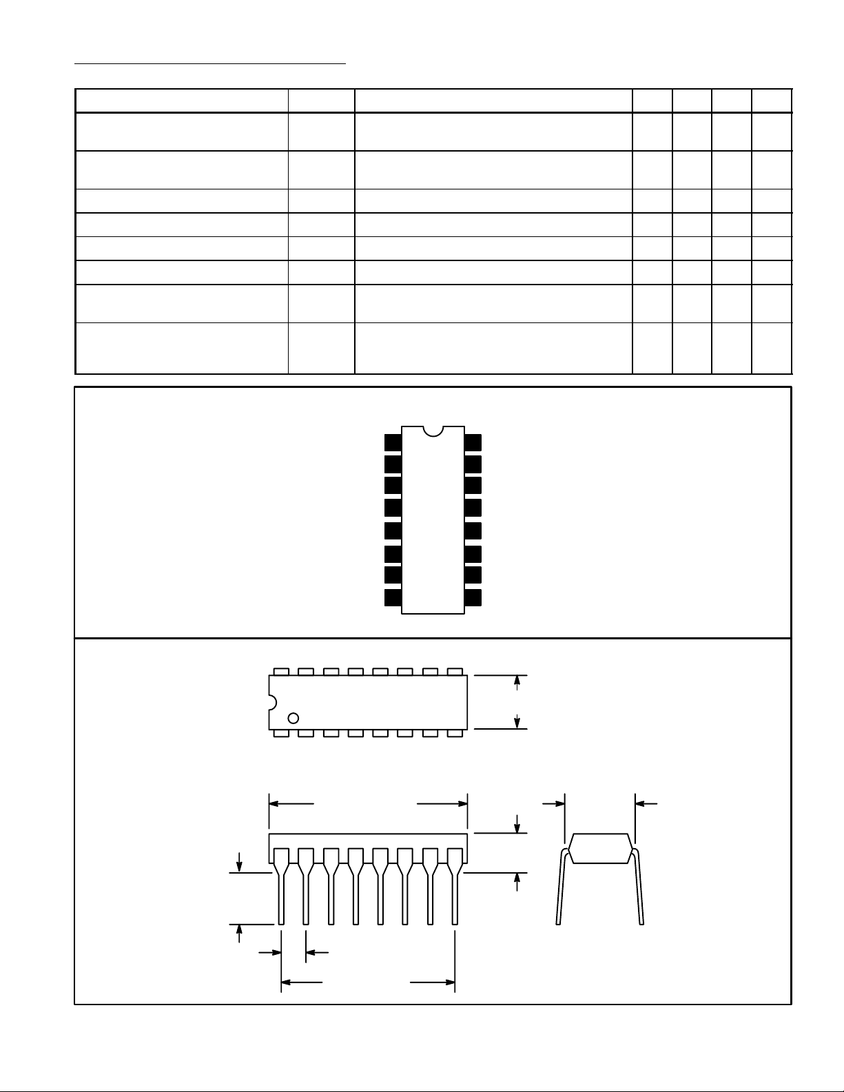
Pin Connection Diagram
1st IF Input
2nd IF Input
3rd IF Input
GND
in
= 100dBµ, +150kHz detuned, the voltage
1
2
3
4
5
6
7
8
16
Level Control
15
Center Meter
GND
14
Signal Motor Drive
13
Mute Switch
12
V
11
CC
Quadrature Tank
10
Quadrature Tank
9
60 100 160 kHz
36 43 60 dBµ
60 81 – dB
–30 +7 +30 mV
.245
(6.22)
Min
16 9
.260 (6.6) Max
18
.785 (19.9)
Max
.300
(7.62)
.200 (5.08)
Max
.100 (2.54)
.700 (17.7)
 Loading...