

NTE NTE155 Datasheet
NTE131 (PNP) & NTE155 (NPN)
Germanium Complementary Transistors
Audio Power Amplifier
Description:
The NTE131 (PNP) and NTE155 (NPN) are Germanium PNP Alloy Junction transistors in a Japanese
TO66 type package designed for use in audio power amplifier applications.
Absolute Maximum Ratings:
(TA = +25°C unless otherwise specified)
Collector–Base Voltage, V
CBO
32V. . . . . . . . . . . . . . . . . . . . . . . . . . . . . . . . . . . . . . . . . . . . . . . . . . . . . . .
Collector–Emitter Voltage, V
CES
32V. . . . . . . . . . . . . . . . . . . . . . . . . . . . . . . . . . . . . . . . . . . . . . . . . . . . . .
Emitter–Base Voltage, V
EBO
10V. . . . . . . . . . . . . . . . . . . . . . . . . . . . . . . . . . . . . . . . . . . . . . . . . . . . . . . . .
Collector Current, I
C
1A. . . . . . . . . . . . . . . . . . . . . . . . . . . . . . . . . . . . . . . . . . . . . . . . . . . . . . . . . . . . . . . . .
Base Current, I
B
200mA. . . . . . . . . . . . . . . . . . . . . . . . . . . . . . . . . . . . . . . . . . . . . . . . . . . . . . . . . . . . . . . .
Power Dissipation, P
C
6W. . . . . . . . . . . . . . . . . . . . . . . . . . . . . . . . . . . . . . . . . . . . . . . . . . . . . . . . . . . . . .
Operating Junction Temperature, T
J
+90°C. . . . . . . . . . . . . . . . . . . . . . . . . . . . . . . . . . . . . . . . . . . . . . . .
Storage Temperature Range, T
stg
–55° to +90°C. . . . . . . . . . . . . . . . . . . . . . . . . . . . . . . . . . . . . . . . . . .
Note 1. NTE131MP is a matched pair of NTE131 with their DC Current Gain (h
FE
) matched to within
10% of each other.
Electrical Characteristics:
(TA = +25°C unless otherwise specified)
Parameter Symbol Test Conditions Min Typ Max Unit
Collector Cutoff Current I
CEV
VCE = 32V, VEB = 1V – – 1 mA
Emitter Cutoff Current I
EBO
VEB = 10V, IC = 0 – – 1 mA
DC Current Gain h
FE1
VCB = 0, IE = 100mA 35 – 170
h
FE2
VCB = 0, IE = 1A 36 – 185
Common–Emitter Cutoff Frequency f
α
e
VCB = 2V, IE = 100mA 10 15 – kHz
Base–Emitter ON Voltage V
BE
VCB = 0, IE = 1A – 0.4 – V
Collector–Emitter Saturation Voltage V
CE(sat)IC
= 1A, IB = 100mA – 0.08 – V
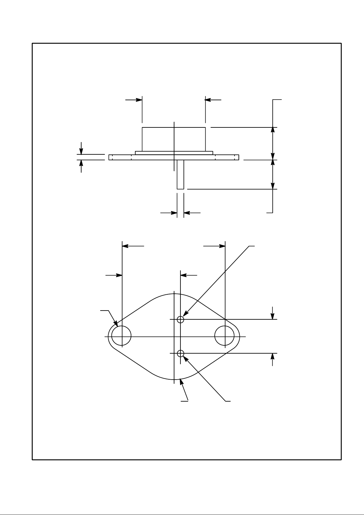
.593 (15.08)
Dia
.031
(.792)
.290 (7.36)
.295 (7.5)
.039 (1.0) Dia
.944 (24.0)
Base
.530 (13.5)
.315
(8.0)
Emitter
Collector/Case
.157 (4.0)
Dia
(2 Places)
 Loading...