

NTE NTE1539 Datasheet

NTE1539
Integrated Circuit
Color TV Sync Deflection Circuit
Description:
The NTE1539 is a multifunctional integrated circuit which is based on the internal circuit of the
NTE1538. It incorporates various functions required for synchronization and deflection circuits of color television sets and especially aims at increasing the detections accuracy of the X–ray protection
circuit. The ground pins for horizontal and vertical are provided separately to enable the easy layout
of the printed circuit board.
The NTE1539 differs from the NTE1538 in the following points:
D The output circuit of synchronizing separation is emitter follower type
D The X–ray protection circuit is differential dual inouts thyristor system
D The ground pins for horizontal and vertical are provided separately.
Functions:
D Synchro Separator
D Horizontal AFC
D Vertical Driver
D Vertical Blanking Pulse Making
D Horizontal Oscillator
D Vertical Oscillator
D X–Ray Protector
Features:
D Multifunctional and Small–Size
D Minimum Number of Parts Required
D Horizontal and Vertical Oscillators being Stable to Variation of Ambient Temperature and Supply
Voltage Owing to Small Warming–Up Drift.
D Small Variation of Horizontal Oscillation Frequency
D Good Linearity and Interface Owing to DC Bias at Vertical Output Stage being Sampling
Controlled within Retrace Time.
D Vertical Blanking Pulse Width being Freely Set Up According to Peripheral Parts.
D High Detection Accuracy of X–Ray Protection Circuit.
Absolute Maximum Ratings: (TA = +25°C unless otherwise specified)
Maximum Supply Voltage, V
Maximum Supply Current, I
14
17
Allowable Power Dissipation (TA = +60°C), PDmax 450mW. . . . . . . . . . . . . . . . . . . . . . . . . . . . . . . . . .
Operating Temperature Range, T
Storage Temperature Range, T
stg
opg
–20° to +85°C. . . . . . . . . . . . . . . . . . . . . . . . . . . . . . . . . . . . . . . . .
–55° to +125°C. . . . . . . . . . . . . . . . . . . . . . . . . . . . . . . . . . . . . . . . . .
Recommended Operating Condition: (TA = +25°C unless otherwise specified)
Recommended Supply Voltage, V
14
14V. . . . . . . . . . . . . . . . . . . . . . . . . . . . . . . . . . . . . . . . . . . . . . . . . . . . . . .
16mA. . . . . . . . . . . . . . . . . . . . . . . . . . . . . . . . . . . . . . . . . . . . . . . . . . . . . .
12V. . . . . . . . . . . . . . . . . . . . . . . . . . . . . . . . . . . . . . . . . . . . . . . . . .
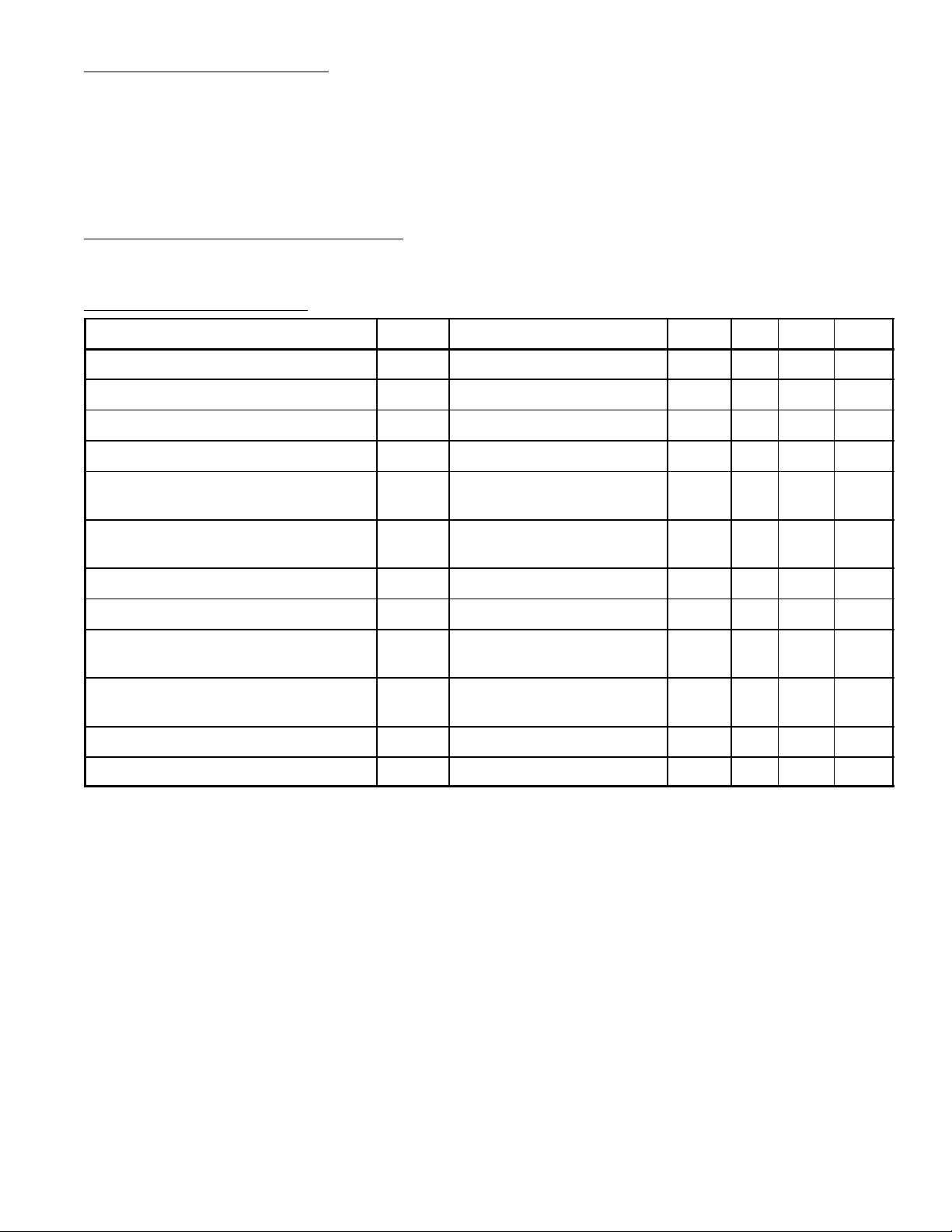
Electrical Characteristics: (TA = +25°C, V14 = 12V, I
= 13mA unless otherwise specified)
CC17
Parameter Symbol Test Conditions Min Typ Max Unit
V
Current Dissipation I
CC14
V
Supply Voltage V
CC17
CC14
CC17
9.0 – 15.0 mA
11.8 – 13.2 V
Vertical Frequency Pull–In Range 9.0 – 11.0 Hz
Vert Free Running Frequency f
Supply Voltage Dependence of
fv center 55Hz 50 – 60 Hz
v
V14 = 12 ±1V, 55Hz at 12V –0.5 – 0.5 Hz
Vertical Frequency
Temperature Characteristic of
TA = –10° to +60°C –0.028 – 0.028 Hz/°C
Vertical Frequency
Vertical Driver Amplification Factor 4.0 – 7.0 times
Horizontal Free Running Frequency f
Supply Voltage Dependence of
fH center 15.734kHz –750 – 750 Hz
H
VZ–VZ x 90% –50 – 50 Hz
Horizontal Frequency
Temperature Characteristic of
TA = –10° to +60°C (IC only) –3.4 – 3.4 Hz/°C
Horizontal Frequency
Horizontal Output Pulse Width fH = 15.734kHz 21.5 – 26.5 µs
Horizontal Output Drive Current 4.9 – 8.3 mA
 Loading...