

NTE1519
Integrated Circuit
10–Step LED Driver Circuit for Linear Scale
Features:
D 10 LED Bar Display Driver
D Linear Scale Display
D Continuous 10 LED Display
D By Connecting in Series, Can Display More than 10 LEDs
Absolute Maximum Ratings: (TA = +25°C unless otherwise specified)
Supply Voltage, V
Power Dissipation, P
Derate Above 25°C 5mW/°C. . . . . . . . . . . . . . . . . . . . . . . . . . . . . . . . . . . . . . . . . . . . . . . . . . . . . . .
Operating Temperature Range, T
Storage Temperature Range, T
Electrical Characteristics: (TA = +25°C, VCC = 12V unless otherwise specified)
CC
D
opr
stg
20V. . . . . . . . . . . . . . . . . . . . . . . . . . . . . . . . . . . . . . . . . . . . . . . . . . . . . . . . . . . . . . . .
750mW. . . . . . . . . . . . . . . . . . . . . . . . . . . . . . . . . . . . . . . . . . . . . . . . . . . . . . . . . . .
–30° to +75°C. . . . . . . . . . . . . . . . . . . . . . . . . . . . . . . . . . . . . . . . .
–55° to +125°C. . . . . . . . . . . . . . . . . . . . . . . . . . . . . . . . . . . . . . . . . .
Parameter Symbol Test Conditions Min Typ Max Unit
Supply Voltage V
Supply Current I
CC(1)
I
CC(2)
Internal Resistance R
Input Bias Current I
Input Voltage Range V
Output Offset Voltage V
Output Voltage, High Level V
Output Voltage, Low Level V
Output Current I
Leakage Current I
CC
TOT
IN
IN
OFF
OH
OL
O
IL
6 12 15 V
V
max = 4V, VIN = 0V – 15 20 mA
ref
V
max = 4V, VIN = 4.1V, IO = 10mA x 10 – 150 160 mA
ref
7 9 11 kΩ
VIN = GND – –0.25 –1.0 µA
0 – 8 V
V
= 4V –40 – 40 mV
ref
V
= 4V, VIN = GND, RL = 1.5kΩ 11.9 11.93 – V
ref
V
= 4V, VIN = 4.1V, RL = 1.5kΩ – 0.6 1.0 V
ref
V
= 4V, VIN = 4.1V – 7 12 mA
ref
VIN = 4V, V
max = 0V, V
ref
min = 0V – – 15 µA
ref
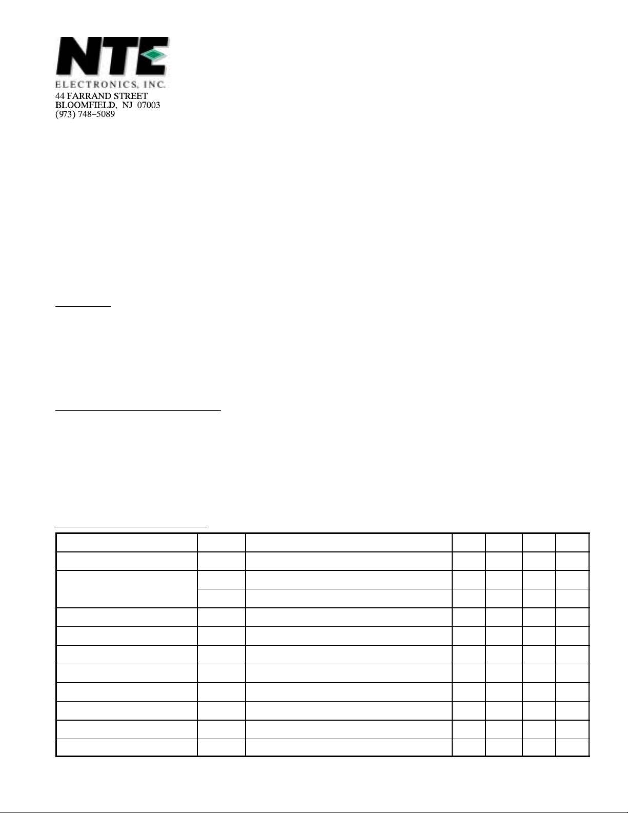
Pin Connection Diagram
1
2
3
4
5
6
7
V
GND
Min
ref
VO1
VO2
VO3
VO4
VO5
8Dimmer 9
16 9
16
15
14
13
12
11
10
V
IN
V
Max
ref
V
CC
VO10
VO9
VO8
VO7
VO6
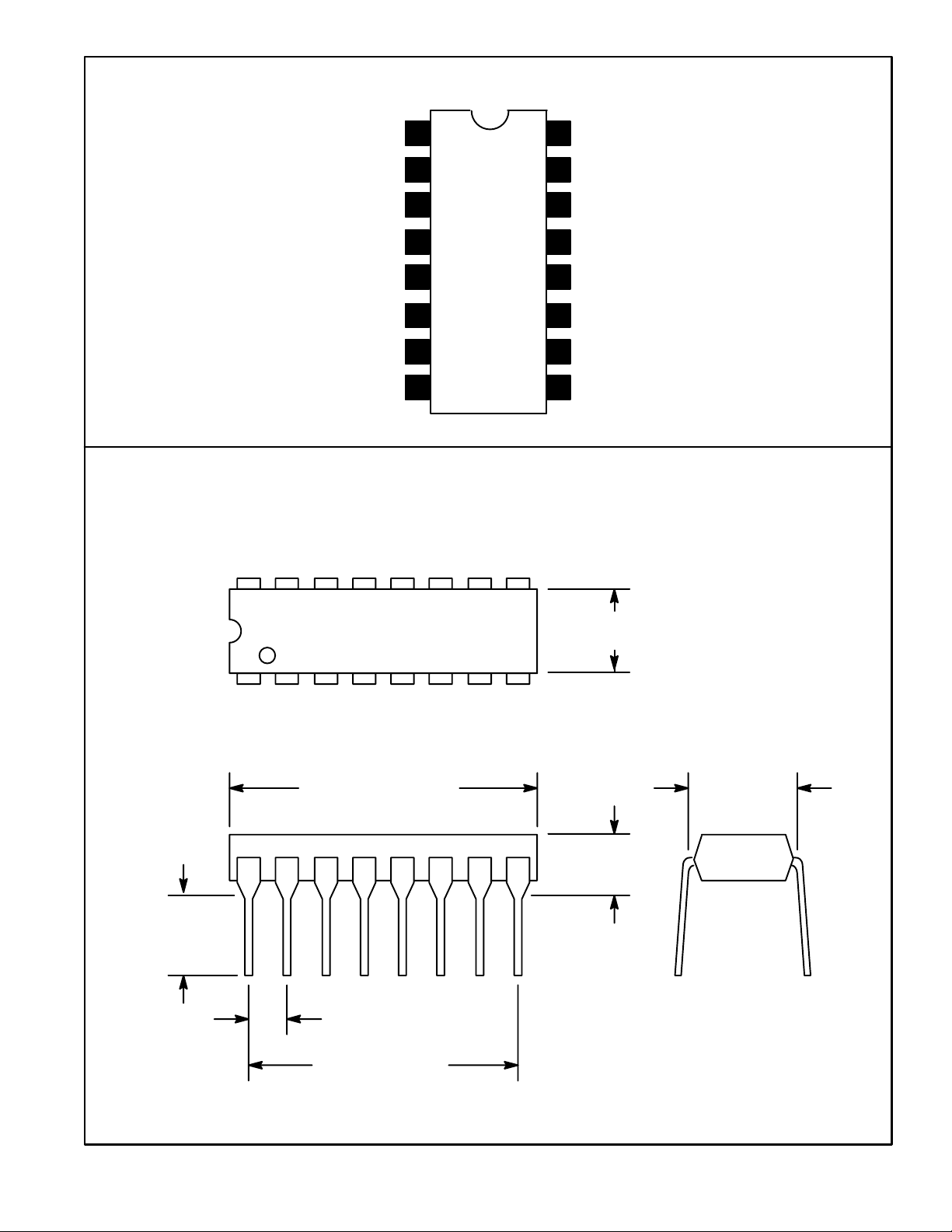
.245
(6.22)
Min
.260 (6.6) Max
18
.785 (19.9) Max
.300 (7.62)
.200 (5.08)
Max
.100 (2.54)
.700 (17.7)
 Loading...