

NTE NTE15039 Datasheet
NTE15039
Integrated Circuit
VHS/VCR Chroma Signal Proessor for
NTSC/PAL/SECAM Systems
Description:
The NTE15039 is a multifunctional IC in a 24–Lead DIP type package that contains VHS VCT chroma
signal processing circuitry. Since the package is small and a minimum number of external components are required, the NTE15039 occupies much less space on the PC board thus facilitating VCR
design. The chroma section is made adjustment–free (except REC chroma level) thus streamlining
the manufacture of VCRs
Features:
D Designed for NTSC/PAL/MESECAM Systems
D Adjustment–Free Chroma Section (Except REC Chroma Level)
D Few External Components Required
D LPF Usable for REC/PB
D Multifunctional:
2fSC Generator for CCD Drive
Function to Select APC Loop Input Signal Passed/Not Passed Through Comb Filter
3rd Lock Protector of VXO
Absolute Maximum Ratings: (TA = +25°C unless otherwise specified)
Maximum Supply Voltage, VCCmax 7V. . . . . . . . . . . . . . . . . . . . . . . . . . . . . . . . . . . . . . . . . . . . . . . . . . . .
Allowable Power Dissipation (TA ≤ +65°C), PDmax 850mW. . . . . . . . . . . . . . . . . . . . . . . . . . . . . . . . . . .
Operating Temperature Range, T
Storage Temperature Range, T
stg
opg
–10° to +65°C. . . . . . . . . . . . . . . . . . . . . . . . . . . . . . . . . . . . . . . . .
–40° to +125°C. . . . . . . . . . . . . . . . . . . . . . . . . . . . . . . . . . . . . . . . . .
Recommended Operating Conditions: (TA = +25°C unless otherwise specified)
Recommended Supply Voltage, V
CC
Operating Voltage Range, VCCop 4.8 to 5.5V. . . . . . . . . . . . . . . . . . . . . . . . . . . . . . . . . . . . . . . . . . . . . .
Electrical Characteristics: (TA = +25°C, VCC = 5V unless otherwise specified)
Parameter Symbol Test Conditions Min Typ Max Unit
REC Current Dissipation I
REC Output Level V
REC ACC Characteristics ∆V
CC(R)
O(R)
O(R)
Input ± 6dB –0.5 ±0.1 +0.5
49 62 75 mA
75 110 145 mV
dB
5V. . . . . . . . . . . . . . . . . . . . . . . . . . . . . . . . . . . . . . . . . . . . . . . . . . .
P–P
Electrical Characteristics (Cont’d): (TA = +25°C, VCC = 5V unless otherwise specified)
Parameter Symbol Test Conditions Min Typ Max Unit
ACC Killer Input Level V
VXO Control Sensitivity S
VXO OSC Level V
VXO(R)
Subconverter Output Level V
BGP Delay Time t
BGP Width t
REC APC Pull–in Range ∆f
REC AFC Pull–in Range ∆f
160fH VCO Control Sensitivity S
PB Current Dissipation I
CC(P)
PB Output Level V
PB ACC Characteristic ∆V
PB Main Converter Carrier Leak CL
PB XO Output Level V
PB XO Free–Running Frequency f
XO(P)
XO(f)
2fSC Output Amplitude V
Burst Emphasis Amount G
Burst De–Emphasis Amount G
PAL/NTSC Select Voltage V
NTSC/SECAM Select Voltage V
ACK
VXO
SUB
D
W
APC
AFC
VCO
O(P)
O(P)
(p)
2fsc
BE
BD
P/N
N/S
–25 –22 –19 dB
3.1 4.6 6.9 Hz/mV
0.77 1.01 1.19 V
P–P
97 122 147 mV
– 3.35 – µs
– 4.9 – µs
±350 – – Hz
±1.0 – – kHz
0.75 1.06 1.38 kHz/mV
51 64 77 mA
340 390 450 mV
Input ± 6dB –0.5 – +0.5 dB
5.06MHz component – –38 –33 dB
540 680 840 mV
Difference from 4433619Hz –9 0 +9 Hz
300 430 560 mV
NTSC Mode 5.5 6.0 6.5 dB
NTSC Mode –5.8 –5.55 –5.3 dB
1.0 1.35 1.7 V
3.2 3.55 3.9 V
P–P
P–P
P–P
P–P
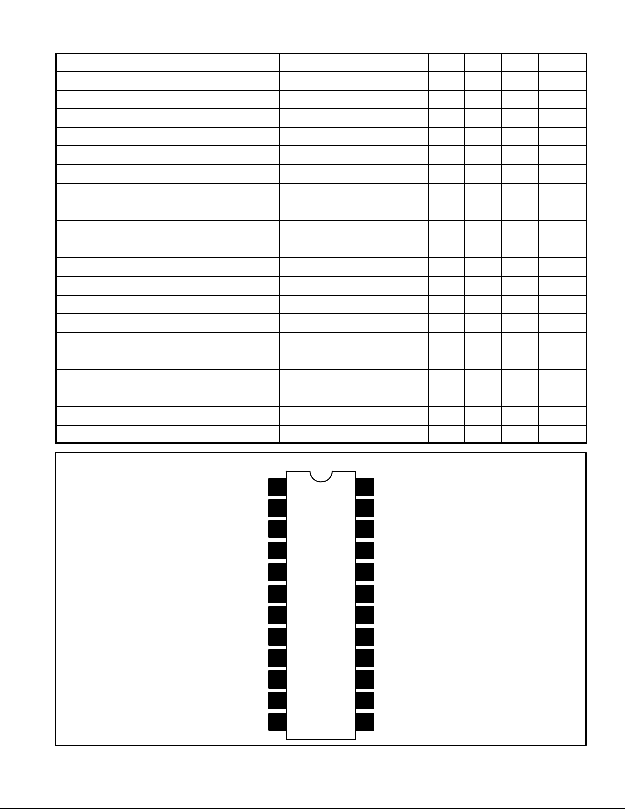
N/P/S Control
ACC Filter
REC Chroma Input
DC Feedback Filter
PB Chroma Input
REC Chroma Output
R/P Switch Control
VCO Filter
Conv Carrier Input
Color Killer Filter
Pin Connection Diagram
1
2
3
4
5BPF Drive
6GND
7
8SLD Output
9
10
11
24
23
22
21
20
19
18
17
16
15
14
12 13
PB Amp Input
Chroma Output
Switch Pulse Input
LP Control Input
REC Video Input
V
CC
XO Input
XO Output
2fSC Output
VCO Tank
REC APC Filter
Sync Input/BPG Output
Sub Conv Output
 Loading...