

NTE NTE1503 Datasheet
NTE1503
Integrated Circuit
5–Step LED Driver Circuit
for Logarithmic Response
Description:
The NTE1503 is an integrated circuit in a 9–Lead SIP type package designed for driving 5–LED bar
graphs or dot displays so that the LEDs may light logarithmically (dB) for input signal. Brightness of
the LEDs can be controlled by using the output current adjustment pin provided.
Features:
D 5–LED Bar Graph or Dot Display Drive
D Logarithmic Response with Respect to Input
D Brightness Externally Adjustable
D High Output Current, Suitable for Green LED Drive
D Lamp ON/OFF Hysteresis, No Flickering by Noise
Absolute Maximum Ratings: (TA = +25°C unless otherwise specified)
Supply Voltage, V
Circuit Voltage, V
Load Current Set Input Voltage, V
Output Voltage (Note 1), V
Supply Current, I
Load Current Set Input Current, I
Output Current, I
Power Dissipation, P
CC
8–5
7–5
O
CC
7
O
D
Operating Ambient Temperature Range, T
Storage Temperatuere Range, T
stg
opr
–0.5V to +18V. . . . . . . . . . . . . . . . . . . . . . . . . . . . . . . . . . . . . . . . . . . . . . . . . . . . . . .
–0.5V to +16V. . . . . . . . . . . . . . . . . . . . . . . . . . . . . . . . . . . . . . . . . . . . . . . . . . . . . . .
+16V. . . . . . . . . . . . . . . . . . . . . . . . . . . . . . . . . . . . . . . . . . . . . . . .
–0.5V to +16V. . . . . . . . . . . . . . . . . . . . . . . . . . . . . . . . . . . . . . . . . . . . . . . .
18mA. . . . . . . . . . . . . . . . . . . . . . . . . . . . . . . . . . . . . . . . . . . . . . . . . . . . . . . . . . . . . . .
4.25mA. . . . . . . . . . . . . . . . . . . . . . . . . . . . . . . . . . . . . . . . . . . . . . . . .
20mA. . . . . . . . . . . . . . . . . . . . . . . . . . . . . . . . . . . . . . . . . . . . . . . . . . . . . . . . . . . . . . . .
550mW. . . . . . . . . . . . . . . . . . . . . . . . . . . . . . . . . . . . . . . . . . . . . . . . . . . . . . . . . . .
–20° to +75°C. . . . . . . . . . . . . . . . . . . . . . . . . . . . . . . . . .
–55° to +150°C. . . . . . . . . . . . . . . . . . . . . . . . . . . . . . . . . . . . . . . . .
Note 1. Output Pin1, Pin2, Pin3, Pin4, and Pin6.
Electrical Characteristics: (TA = +25°C, VCC = 16V unless otherwise specified)
Parameter Symbol Test Conditions Min Typ Max Unit
Input Voltage (LED ON)
LED 1 V
LED 2 V
LED 3 V
LED 4 V
LED 5 V
I(ON)1
I(ON)2
I(ON)3
I(ON)4
I(ON)5
– – 1.12 V
– – 1.86 V
– – 3.10 V
– – 5.18 V
– – 8.66 V
Electrical Characteristics (Cont’d): (TA = +25°C, VCC = 16V unless otherwise specified)
Parameter Symbol Test Conditions Min Typ Max Unit
Input Voltage (LED OFF)
LED 1 V
LED 2 V
LED 3 V
LED 4 V
LED 5 V
I(OFF)1
I(OFF)2
I(OFF)3
I(OFF)4
I(OFF)5
Load Current
Pin6 I
6
Pin1 to Pin4 I1 to I
VO = 1.2V, I7 = 4.25mA 13 16 – mA
VO = 2.5V, I7 = 4.25mA 13 16 – mA
4
Pin1 to Pin4, Pin6 I1 to I4, I6VO = 16V, I7 = 4.25mA – 16 19 mA
0.80 – – V
1.49 – – V
2.54 – – V
4.28 – – V
7.23 – – V
Input Current I
Supply Current I
8
9
V
= 8.7V – – 50 µA
8–5
V
= 16V – – 5 mA
8–5
V
= 16V – – 18 mA
8–5
Output Pin Leakage Current I1 to I4, I6VO = 16V – – 15 µA
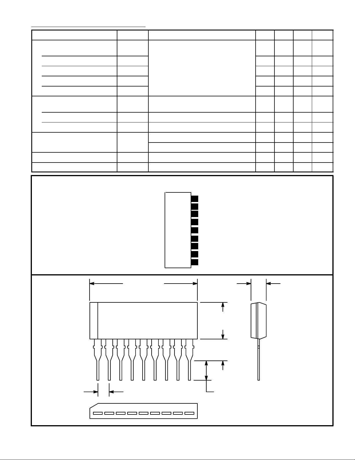
Pin Connection Diagram
(Front View)
9
V
CC
Input
8
Output Current Adjust
7
6
LED 5
GND
5
4
LED 4
LED 3
3
LED 2
2
LED 1
1
.929 (23.6) .118 (3.0)
.236
(6.0)
19
.098
(2.5)
.100 (2.54) .118(3.0)
 Loading...