

NTE NTE1488 Datasheet
NTE1488
Integrated Circuit
FM IF Amp, Demod w/Muting, Center Meter
and Signal Meter
Features:
D Low Distortion
D High Signal–to–Noise Ratio
D High Limiting Sensitivity
D Large Muting Attenuation
D Provides Specific Signal for Direct Drive of a Signal Meter with Good Linearity
D Muting Level is Variable by Adjusting the External Resistor
D Hig Stability Against Abnormal Oscillation
Applications:
D FM IF Amplifier
D Quadrature Detector
D Audio Amplifier
D Muting Circuit
D AFC, Tuning Meter Driver
D AGC Control Voltage Generator
D Muting Control Voltage Generator
D Signal Meter Driver
Absolute Maximum Ratings:
Supply Voltage, V
Power Dissipation (T
Operating Temperature Range, T
Storage Temperature Range, T
Electrical Characteristics:
Parameter Symbol Test Conditions Min Typ Max Unit
Static (DC) Characteristics (VCC = 13V, No Signal)
Pin1 Voltage V
Pin2 Voltage V
Pin3 Voltage V
Pin6 Voltage V
Pin7 Voltage V
Pin10 Voltage V
CC
= +60°C), P
A
T
opr
stg
(TA = +25°C unless otherwise specified)
1
2
3
6
7
10
14V. . . . . . . . . . . . . . . . . . . . . . . . . . . . . . . . . . . . . . . . . . . . . . . . . . . . . . . . . . . . . . . .
590mW. . . . . . . . . . . . . . . . . . . . . . . . . . . . . . . . . . . . . . . . . . . . . . .
–20° to +60°C. . . . . . . . . . . . . . . . . . . . . . . . . . . . . . . . . . . . . . . . .
–55° to +125°C. . . . . . . . . . . . . . . . . . . . . . . . . . . . . . . . . . . . . . . . . .
– 1.95 – V
– 1.95 – V
– 1.95 – V
– 5.60 – V
– 5.60 – V
– 5.60 – V
Electrical Characteristics (Cont’d): (TA = +25°C unless otherwise specified)
Parameter Symbol Test Conditions Min Typ Max Unit
AC Characteristics (VCC = 13V, fc = 10.7MHz, fm = 400Hz, ∆f = 75kHz)
Supply Current I
Limiting Sensitivity V
Reversed AF Voltage V
Total Harmonic Distortion THD Vin = 100dBµ – 0.03 0.10 %
Signal–to–Noise Ratio S/N Vin = 100dBµ 78 84 – dB
AM Rejection Ratio AMR Vin = 100dBµ, AM: fin = 1kHz, Mod.
Muting Attenuation Mute
Muting Bandwidth BW (Mute) Vin = 100dBµ, Sum of + and ∆f for
Muting Sensitivity Vin (Mute) No muting level adjustment (Pin16
Muting Sensitivity Adjustment
Range
Meter Drive Voltage V
AGC Control Voltage V
CC
in(lim)
O(AF)
AVin (Mute) Max. input level with possible muting
13–0
V
13–70
V
13–100
15
Vin = 0dBµ, Pin16 to GND Open 16 25 33 mA
Vin = 100dBµ Input,
Input Level = 3dB from V
Vin = 100dBµ 265 380 510 mV
30%
Vin = 100dBµ, Output s tandard w i th P in5
(Att)
Open, Attenuation with 2V impressed to
Pin5
= 1.4V
V
12
Open) input level for V
level adjustment, Note 1
Vin = 0dBµ, Pin13 Voltage – 0 – V
Vin = 70dBµ, Pin13 Voltage 0.9 1.45 – V
Vin = 100dBµ, Pin13 Voltage 4.7 5.2 – V
Vin = 80dBµ, Pin15 Voltage – 4.3 – V
O(AF)
= 1.4V
12
– 31 37 dBµ
45 54 – dB
70 85 – dB
55 105 145 kHz
36 44 60 dBµ
75 – – dBµ
rms
Note 1. Muting level can be adjusted up to 75dBµ and should be set within this range.
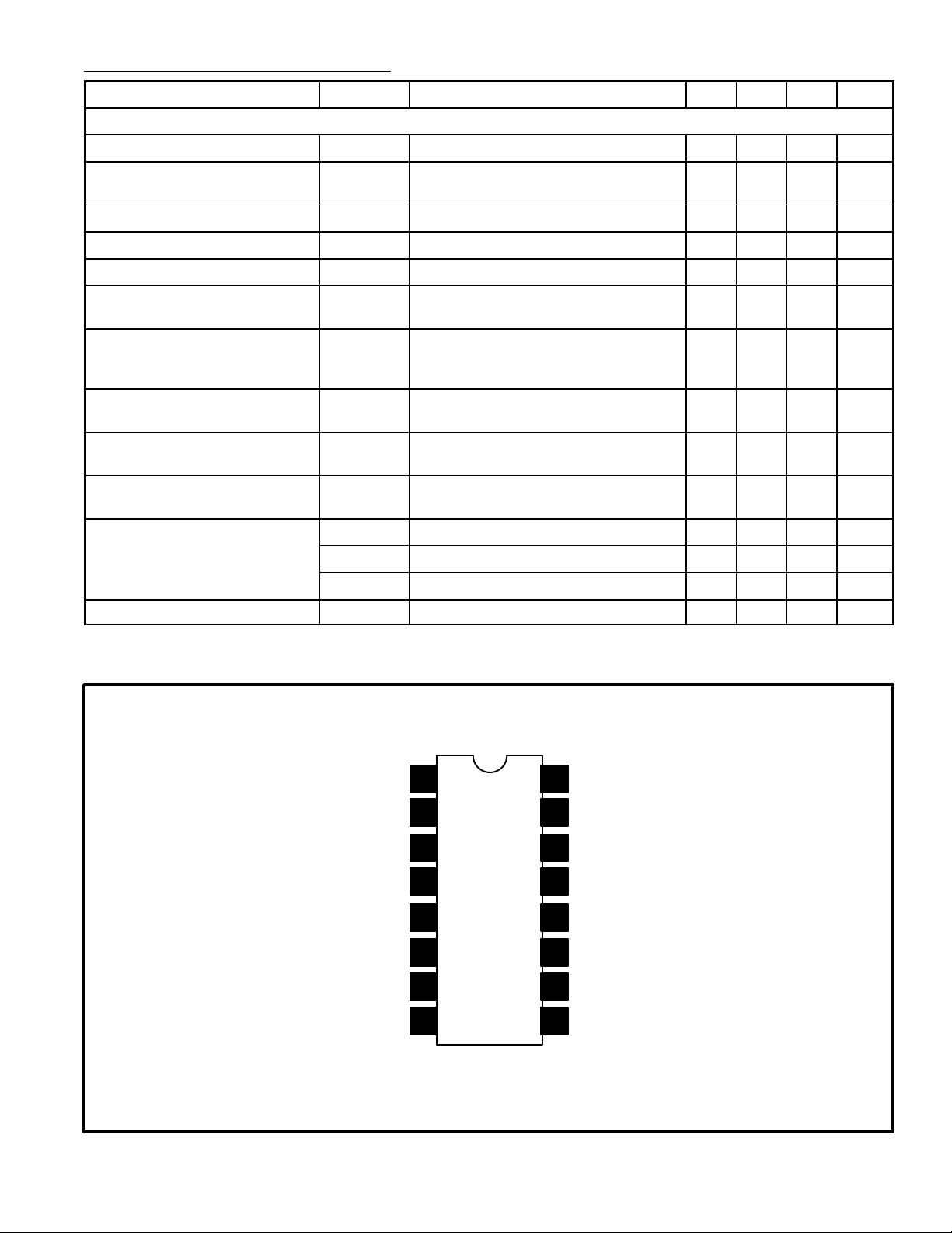
Pin Connection Diagram
Input
AM/FM Switch
Bypass
GND
Audio Output
1
2
3
4
5Mute Input
6
7AFC Output
8Quad Det
Mute Adjust
16
RF AGC
15
14
GND
13
Meter Driver
12 Mute Output
V
11
CC
Det Tank
10
Det Tank
9
 Loading...