

NTE NTE1476 Datasheet

NTE1476
Integrated Circuit
Audio Power Amplifier, 1.4W
Description:
The NTE1476 is an audio power amplifier in a 10–Lead SIP type package designed for use as a power
amplifier in portable cassette tape recorder applications.
Features:
D Recommended Supply Voltage: VCC = 7.5V, 9.0V
D Output Power:
P
= 1.4W (Typ) at VCC = 7.5V, RL = 4Ω
OUT
P
= 2.0W (Typ) at VCC = 9.0V, RL = 4Ω THD = 10%
OUT
D Minimum Operating Voltage: VCC = 5.0V
D Low Quiescent Current
D Excellent Ripple Rejection
D Built in Turn–On Muting Circuit
Absolute Maximum Ratings: (TA = +25°C)
Supply Voltage, VCC 14V. . . . . . . . . . . . . . . . . . . . . . . . . . . . . . . . . . . . . . . . . . . . . . . . . . . . . . . . . . . . . . .
Output Current (Peak), I
O(peak)
Power Dissipation, PD 5.0W. . . . . . . . . . . . . . . . . . . . . . . . . . . . . . . . . . . . . . . . . . . . . . . . . . . . . . . . . . . . .
Operating Temperature Range, T
Storage Temperature Range, T
1.8A. . . . . . . . . . . . . . . . . . . . . . . . . . . . . . . . . . . . . . . . . . . . . . . . . . . . .
–20° to +75°C. . . . . . . . . . . . . . . . . . . . . . . . . . . . . . . . . . . . . . . . .
opr
–55° to +150°C. . . . . . . . . . . . . . . . . . . . . . . . . . . . . . . . . . . . . . . . . .
stg
Electrical Characteristics: (TA = +25°C, RL = 4Ω, Rg = 600Ω, Rf = 150Ω, f = 1kHz unless
otherwise specified)
Parameter Symbol Test Conditions Min Typ Max Unit
Quiescent Current I
Output Power P
CCQ
OUT
VCC = 5V 55 – – mA
VCC = 9V 7 – 30 mA
VCC = 14V – – 35 mA
THD = 10% VCC = 5V – 0.65 – W
VCC = 7.5V – 1.4 – W
VCC = 9V 1.5 2.0 – W
Electrical Characteristics (Cont’d): (TA = +25°C, RL = 4Ω, Rg = 600Ω, Rf = 150Ω, f = 1kHz
unless otherwise specified)
Parameter Symbol Test Conditions Min Typ Max Unit
Total Harmonic Distortion THD P
Open Loop Voltage Gain G
Closed Loop Voltage Gain G
Input Resistance R
Output Noise Voltage V
VO
V
IN
NO
= 100mW VCC = 7.5V – 0.35 – %
OUT
VCC = 9V – 0.35 1.0 %
VCC = 9V, Rf = 0, VIN = 0.245mV
rms
VCC = 9V, Rf = 150Ω, VIN = 3.9mV
VCC = 9V, V
OUT
= 1V
rms
rms
– 72 – dB
– 46 – dB
25 30 – kΩ
VCC = 9V, Rg =10kΩ, BW = 50Hz to 20kHz – – 1.0 mV
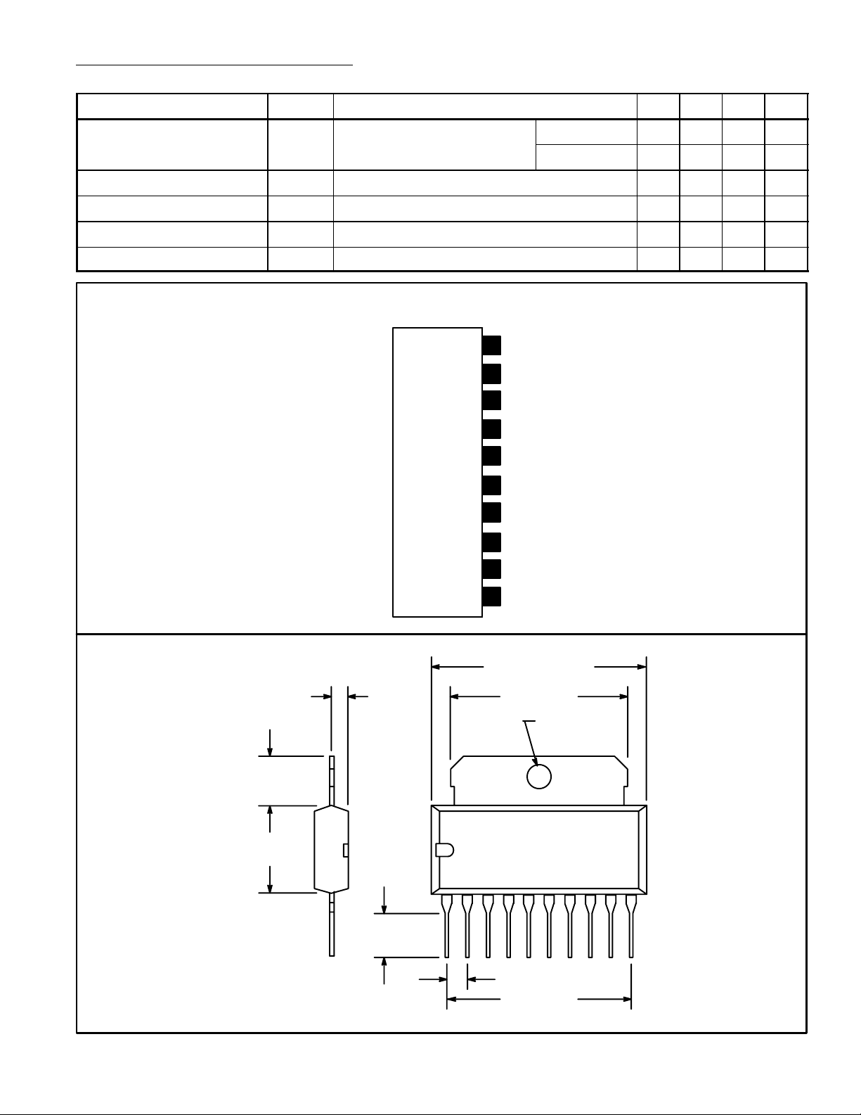
Pin Connection Diagram
(Front View)
Output
10
GND
9
50pf to Pin7
8
7 50pf to Pin8
Feedback
6
Input Low
5
4
Input High
.276
(7.0)
.433
(11.0)
.079
(2.0)
.217 (5.5)
Bypass
3
Bypass
2
1
V
CC
1.050 (26.67) Max
.867 (22.0)
.128 (3.2) Dia
110
.100 (2.54)
.900 (22.8)
 Loading...