

NTE NTE1439 Datasheet
NTE1439
Integrated Circuit
Dual Attenuator
Description:
The NTE1439 is an integrated circuit in a 14–Lead DIP type package which logarithmically controls
the throughput (gain) of an audio signal by the DC voltage or resistance value and has 2 circuits. Since
voltage is internally stabilized, the stable operations are assured at the allowable supply voltage range
(8V to 14.4V). The current source is provided with control circuit so that operation can be controlled
by the voltage drop. This device is used for electronic volume control in radio, television, stereo, tape
recorder, an transceiver applications.
Features:
D Wide Operating Voltage Range
D High Attenuation Level
D Easy to Control Signal Gain with a Simple Circuit
D Less Crosstalk Between Each Channel
Absolute Maximum Ratings: (TA = +25°C unless otherwise specified)
Supply Voltage, V
Circuit Voltage (Note 1), V6, V
Circuit Voltage, V3, V
Total Current Dissipation, I
Total Power Dissipation, P
CC
13
. . . . . . . . . . . . . . . . . . . . . . . . . . . . . . . . . . . . . . . . . . . . . . . . . . . . . . . . . . . . . .
10
tot
tot
Operating Ambient Temperature Range, T
Storage Temperature Range, T
stg
opr
–20° to +75°C. . . . . . . . . . . . . . . . . . . . . . . . . . . . . . . . . .
–55° to +150°C. . . . . . . . . . . . . . . . . . . . . . . . . . . . . . . . . . . . . . . . . .
14.4V. . . . . . . . . . . . . . . . . . . . . . . . . . . . . . . . . . . . . . . . . . . . . . . . . . . . . . . . . . . . . .
6V. . . . . . . . . . . . . . . . . . . . . . . . . . . . . . . . . . . . . . . . . . . . . . . . . . . . . . .
V
CC
25mA. . . . . . . . . . . . . . . . . . . . . . . . . . . . . . . . . . . . . . . . . . . . . . . . . . . . . . .
360mW. . . . . . . . . . . . . . . . . . . . . . . . . . . . . . . . . . . . . . . . . . . . . . . . . . . . . .
Note 1. DC voltage must not be applied to Pin1, Pin2, Pin8, and Pin9 from the outside. 6V is used
as voltage for V6 and V13 and no larger than VCC voltage.
Electrical Characteristics: (TA = +25°C, VCC = 12V unless otherwise specified)
Parameter Symbol Test Conditions Min Typ Max Unit
Gain G
Gain Ratio (Ch2/Ch1) G
V3(2)/GV3(1)vi
V1
G
V2
G
V3
vi = 100mV, V
vi = 100mV, V
vi = 100mV, V
= 100mV, V
= 5V, f = 1kHz 11.7 – 15.7 dB
cont
= 4V, f = 1kHz 10.5 – 15.0 dB
cont
= 3V, f = 1kHz –14 – 2 dB
cont
= 3V, f = 1kHz –6 – +6 dB
cont
Note 2. The same measurement should be applied for Ch2.
Electrical Characteristics (Cont’d): (TA = +25°C, VCC = 12V unless otherwise specified)
Parameter Symbol Test Conditions Min Typ Max Unit
Residual Noise v
Noise v
O
N
vi = 100mV, VC = 1V, f = 1kHz, B = 20kHz – – 100 µV
vi = 0V, VC = 3.5V, B = 20kHz – – 150 µV
Crosstalk CT vi = 500mV, VC = 5V, f = 1kHz 60 – – dB
Output DC Voltage V
Output Voltage Fluctuation ∆V
Control Input Current –I
Supply Current I
O
O
cont
CC
VC = 5V 5.7 – 8.2 V
VC = 5V to 0V –0.65 – +0.65 V
R
= 0 Ω 0.15 – 0.33 mA
cont
R
= 20kΩ 0.15 – 0.33 mA
cont
VC = 5V – – 22 mA
Distortion Factor THD vi = 100mV, VC = 5V, f = 1kHz – – 0.5 %
D6 Breakdown V
(BR)D
I6, I13 = 10µA 6 – – V
Note 2. The same measurement should be applied for Ch2.
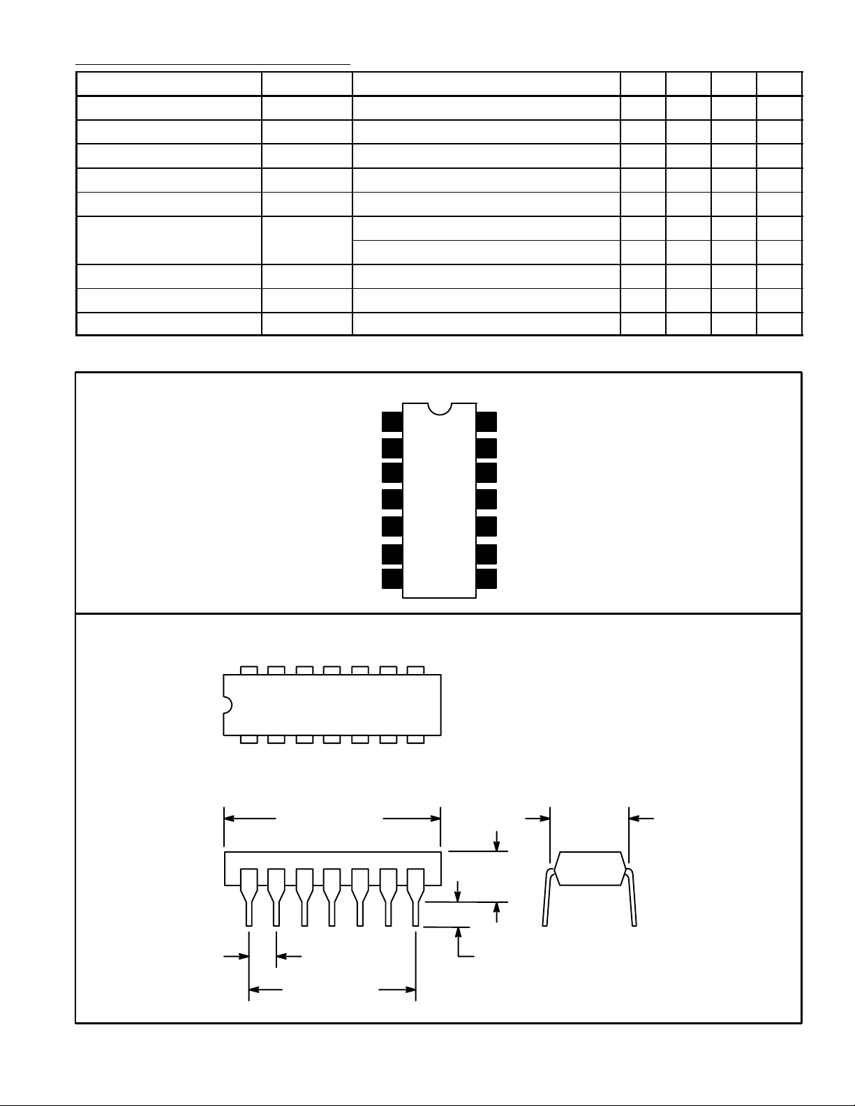
Pin Connection Diagram
Ch 1 Input
Ch 1 Equalize
Ch 1 Output
GND
1
2
3
4
14
N.C.
Ch 1 Control
13
Ch 1 V
12
11
N.C.
CC
Ch 2 V
CC
5
6Ch 2 Control
7N.C.
Ch 2 Output
10
Ch 2 Equalize
9
8 Ch 2 Input
14 8
17
.785 (19.95)
Max
.200 (5.08)
Max
.300
(7.62)
.100 (2.45) .099 (2.5) Min
.600 (15.24)
 Loading...