

NTE NTE1415 Datasheet
NTE1415
Integrated Circuit
Color Compensation Circuit
Absolute Maximum Ratings: (TA = +25°C unless otherwise specified)
Supply Voltage (V
Power Dissipation, P
Operating Temperature Range, T
Storage Temperature Range, T
Electrical Characteristics: (TA = +25°C unless otherwise specified)
Parameter Symbol Test Conditions Min Typ Max Unit
8–21
D
), V
CC
opr
stg
14.4V. . . . . . . . . . . . . . . . . . . . . . . . . . . . . . . . . . . . . . . . . . . . . . . . . . . . . . .
700mW. . . . . . . . . . . . . . . . . . . . . . . . . . . . . . . . . . . . . . . . . . . . . . . . . . . . . . . . . . .
–20° to +70°C. . . . . . . . . . . . . . . . . . . . . . . . . . . . . . . . . . . . . . . . .
–20° to +150°C. . . . . . . . . . . . . . . . . . . . . . . . . . . . . . . . . . . . . . . . . .
Circuit Current I
Tint Manual Output Level V
9–2(H)
V
Color Manual Output Level V
Tint Auto Output Level V
Color Auto Output Level V
20–21(H)
V
20–21(L)
11–21(H)VCC1
V
11–21(L)
19–21(H)VCC2
V
19–21(L)
VIR Detection Level V
Tint Manual Coltrol Sensitivity S
Color Manual Control Sensitivity S
Tint Auto Control Sensitivity S
Color Auto Control Sensitivity S
Tint Preference Control Sensitivity S
8
I
17
9–2(L)
VR
TM
CM
TA
CA
TP
= V
= V
20 26 33 mA
5 12 19 mA
10.3 11.0 11.7 V
0.6 1.3 2.0 V
9.5 10.2 10.9 V
0 – 0.3 V
= 12V 9.5 10.2 10.9 V
8–21
0.4 1.7 2.7 V
= 5.1V 10.1 10.9 11.7 V
17–21
0.4 1.8 3.1 V
0.23 0.28 0.33 V
0.83 0.94 1.05 times
0.86 0.97 1.08 times
40 43 46 dB
41.5 44.5 47.5 dB
–1.5 –1.3 –1.1 times
Pin Connection Diagram
To Chroma Processor
From Chroma Processor
Color Track Switch
GND
To Chroma Processor
To Chroma Processor
From Chroma Processor
1
2
3
4
5
6
7
14 8
Auto Color Switch Input
14
From Chroma Processor
13
12
V
CC
Auto Color Amp Output
11
Color Crystal
10
Color Crystal
9
22pF Bypass
8
17
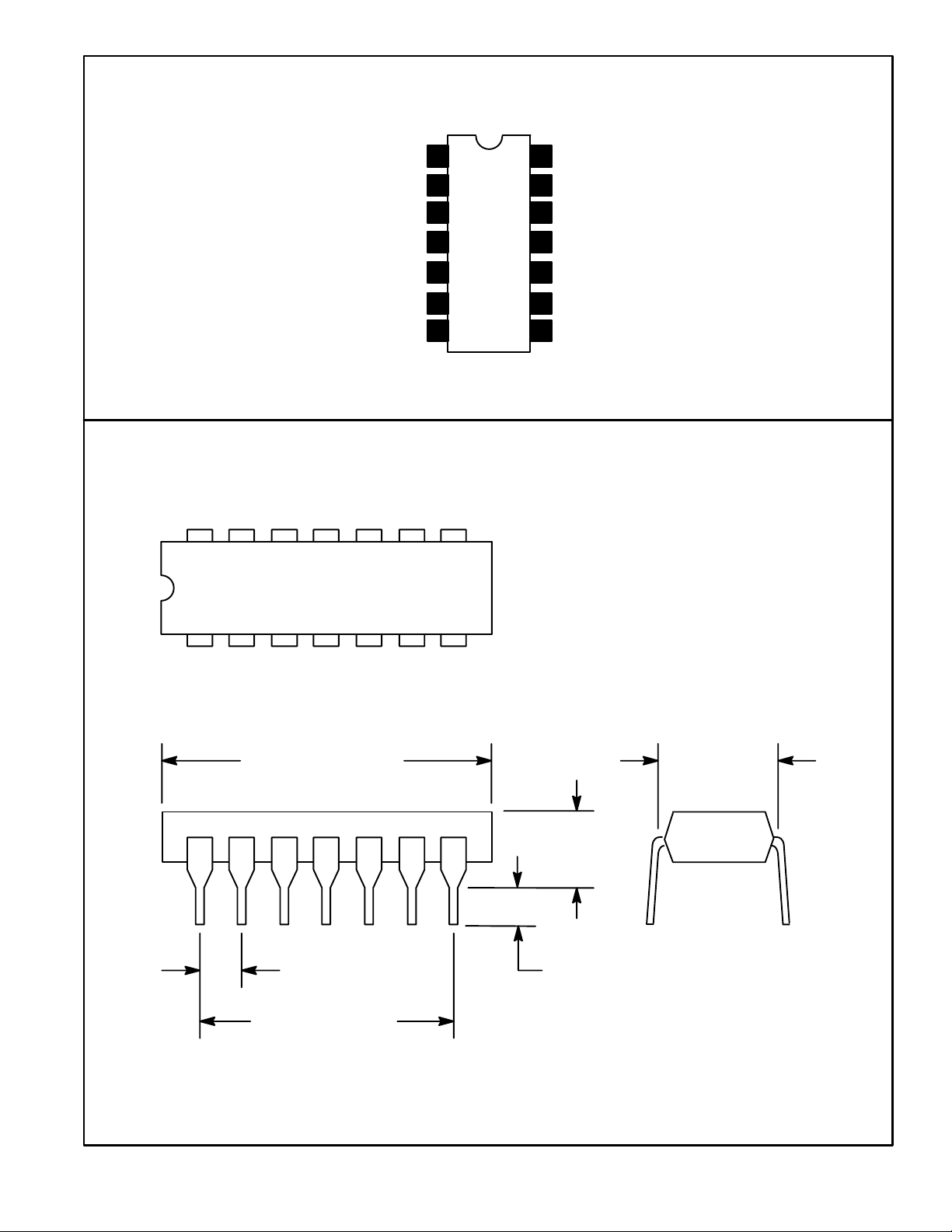
.785 (19.95) Max
.300 (7.62)
.200
(5.08)
Max
.100 (2.45) .099 (2.5) Min
.600 (15.24)
 Loading...