

NTE1404
Integrated Circuit
TV Sound IF Amplifier, Detector, AF Output Circuit
Description:
The NTE1404 is an integrated circuit in a 16–Lead DIP w/Fin type package designed for use as a TV
sound signal processing circuit.
Features:
D Provides Total TV Sound Signal Processing Circuitry from IF Amplifier through AF Output
D DC Volume Control System: Control Voltage 0V to V
D Fixed Detection Output Terminal for TV Sound Multiplex Application
CC
Absolute Maximum Ratings:
Supply Voltage, V
Supply Voltage, V
Circuit Voltage, V
Circuit Current (Peak), I
Power Dissipation, P
CC1
CC2
. . . . . . . . . . . . . . . . . . . . . . . . . . . . . . . . . . . . . . . . . . . . . . . . . . . . . . . .
6–16
8
D
(TA = +25°C unless otherwise specified)
Detector, DCVR Circuit 0.6W. . . . . . . . . . . . . . . . . . . . . . . . . . . . . . . . . . . . . . . . . . . . . . . . . . . . . . .
Output Circuit 1.6W. . . . . . . . . . . . . . . . . . . . . . . . . . . . . . . . . . . . . . . . . . . . . . . . . . . . . . . . . . . . . . .
Operating Ambient Temperature Range, T
Storage Temperature Range, T
stg
opr
Note 1. + and – are flow–in and flow–out current to/from the circuit respectively.
Electrical Characteristics:
Parameter Symbol Test Conditions Min Typ Max Unit
DC Characteristics
Total Circuit Current I
Circuit Voltage V
(TA = +25°C unless otherwise specified)
V
= 12V 23 – 42 mA
3–16
V
= 12V,
3–16
Pin14 and Pin15 are connected
V
V
V
13–16
tot
1–16
4–16
8–16
3.2 4.0 4.8 V
5.8 6.6 7.7 V
8.8 9.5 10.2 V
6.6 7.6 8.5 V
V
–20° to +70°C. . . . . . . . . . . . . . . . . . . . . . . . . . . . . . . . . .
–55° to +150°C. . . . . . . . . . . . . . . . . . . . . . . . . . . . . . . . . . . . . . . . . .
3–16
V
7–16
6V to V
–1.2 to +1.2A. . . . . . . . . . . . . . . . . . . . . . . . . . . . . . . . . . . . . . . . . . . . . . . . . . .
to 13.8V. . . . . . . . . . . . . . . . . . . . . . . . . . . . . . . . . . . . . . . . . . . . . . . . . . . . . .
to 26V. . . . . . . . . . . . . . . . . . . . . . . . . . . . . . . . . . . . . . . . . . . . . . . . . . . . . . .
3–16
Electrical Characteristics (Cont’d): (TA = +25°C unless otherwise specified)
Parameter Symbol Test Conditions Min Typ Max Unit
IF Amplification Detector
Input Limiting Sensitivity V
i(lim)fo
= 4.5MHz, fm = 400Hz, ∆f = ±25kHz – 250 400 µV
AM Rejection AMR fo = 4.5MHz, fm = 400Hz, MOD = 30%
= 100mV
i
rms
rms
Input Resistance R
Input Capacitance C
Output Voltage (Det.) V
Total Harmonic Distortion THD
(AM), V
f = 4.5MHz 6 18 100 kΩ
i
f = 4.5MHz 4 8 12 pF
i
fo = 4.5MHz, fm = 400Hz, ∆f = ±25kHz,
O
Vi = 100mV
(IF)
Volume Circuit
Attenuation (Max. Remaining Sound) A
Amplification V
Total Harmonic Distortion THD
13–5
f = 1kHz, Vi = 0.5mV
tt
f = 1kHz, Vi = 0.5mV
f = 1kHz, Vi = 0.5mV
(AF)
, V6 = 0V – 2 5 mV
rms
, V6 = 12V –2 0 +2 dB
rms
, V6 = 12V – 0.15 1.0 %
rms
Output Circuit
Output Power (Max) P
Voltage Gain G
Total Harmonic Distortion THD
Static Circuit Current I
CQ
f = 1kHz, RL = 16Ω, THD = 10% 1.8 2.0 – W
O
f = 1kHz, V
V
f = 1kHz, PO = 1W – 0.7 1.2 %
(out)
i(12)
= 50mV
rms
VCC = 20V 8 20 50 mA
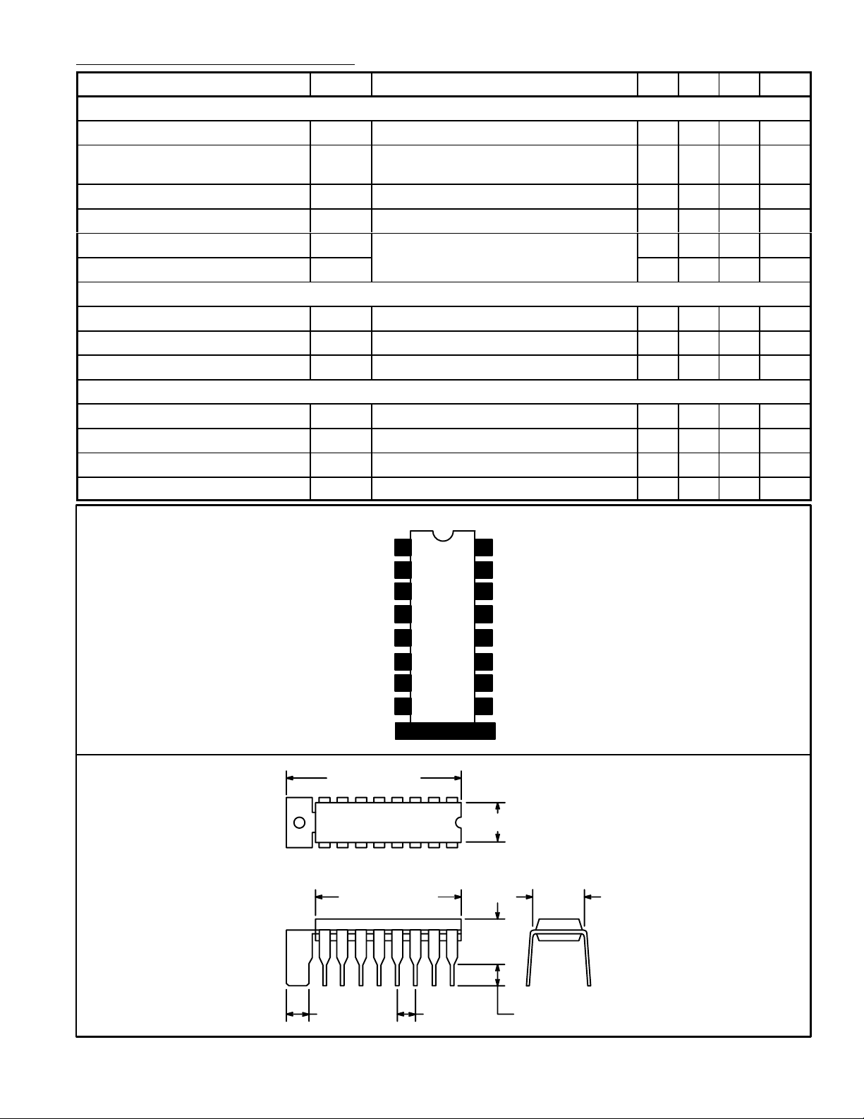
Pin Connection Diagram
38 45 – dB
200 300 440 mV
– 0.3 1.0 %
30 32 34 dB
rms
rms
SIF Output
Detector Input
VCC 1
Detector Input
AF Input
DC Volume
V
CC
AF Output
2
1
2
3
4
5
6
7
8
GND
16
15
Input Bias
SIF Input
14
Variable Output
13
AF Input
12
Filter
11
Feedback
10
GND
9
Tab
1.102 (28.0) Max
17
81
916
.866 (22.0) Max
.256 (6.5)
.200
(5.08)
.300
(7.62)
.122 (3.0).100 (2.54).200 (5.08)
 Loading...