

NTE NTE1389 Datasheet

NTE1389
Integrated Circuit
Dual, Audio Power Amplifier, 20W
Description:
the NTE1389 is an audio power amplifier in a 12–Lead SIP type package specifically designed for
car stereo applications. Typically, it provides 23W output power at 14.4V and 20W at 13.2V on a 4
Ohm load.
This device can be used without capacitors because it incorporates the original short circuit protection
which protects output power transistors and a speaker at the same time when the output terminal is
shorted to ground.
Features:
D Can be used as OCL Connection
D Very Low Output Offset Voltage
D High Output Power
D Very Low Distortion
D Very Low Number of External Low Size Components, Very Simple Mounting System with no
Electrical isolation Between the package and the Heat Sink
D Low Thermal Resistance
D Provides the Following Protective Circuits:
Load Dump Protection
Output Thermal Short Circuit Protection
Thermal Shutdown Protection
Speaker Protection
Absolute Maximum Ratings: (TA = +25°C unless otherwise specified)
Supply Voltage (Note 1), VCCsurge 40V. . . . . . . . . . . . . . . . . . . . . . . . . . . . . . . . . . . . . . . . . . . . . . . . . . .
Quiescent Supply Voltage (Note 2), V
Operational Supply Voltage, V
CC2
CC1
Peak Circuit Current, ICCpeak 4.5A. . . . . . . . . . . . . . . . . . . . . . . . . . . . . . . . . . . . . . . . . . . . . . . . . . . . . . .
package Dissipation, P
Operating Temperature Range (Note 2), T
Storage Temperature Range, T
Note 1. Pulse Width = 200ms, T
Note 2. Using an aluminum heat sink, R
D
–30° to +75°C. . . . . . . . . . . . . . . . . . . . . . . . . . . . . . . . .
–55° to +150°C. . . . . . . . . . . . . . . . . . . . . . . . . . . . . . . . . . . . . . . . . .
stg
≥ 1ms.
rise
opr
= 4°C/W.
thCA
25V. . . . . . . . . . . . . . . . . . . . . . . . . . . . . . . . . . . . . . . . . . . . . .
18V. . . . . . . . . . . . . . . . . . . . . . . . . . . . . . . . . . . . . . . . . . . . . . . . . . . .
20W. . . . . . . . . . . . . . . . . . . . . . . . . . . . . . . . . . . . . . . . . . . . . . . . . . . . . . . . . . .
Recommended Operating Conditions: (TA = +25°C unless otherwise specified)
Parameter Symbol Test Conditions Min Typ Max Unit
Supply Voltage Range V
Load Impedance R
CC
L
9.5 – 16 V
3.2 – 16 Ω
Electrical Characteristics: (TA = +25°C, VCC = 13.2V, RL = 4Ω, f = 1kHz unless otherwise specified)
Parameter Symbol Test Conditions Min Typ Max Unit
Quiescent Current I
Output Offset Voltage V
CC
offsetvin
Output Power P
Voltage Gain A
Total Harmonic Distortion THD PO = 2W – 0.15 1.0 %
Output Noise Level v
Supply Voltage Rejection Ratio SVRR RG = 0, f
Input Resistance R
Rolloff Frequency, High f
Rolloff Frequency, Low f
vin = 0 – 90 180 mA
= 0 – – ±150 mV
VCC = 14.4V THD = 10% – 23 – W
O
VCC = 13.2V THD = 10% 16 20 – W
Vin = 2.45mV 53 55 56 dB
V
RG = 0, BW = 20Hz to 20kHz – 0.65 – mV
n
= 100Hz, v
ripple
i
Av = –3dB from 1kHz Ref. – 90 – kHz
H
L
= 0.5V – 45 – dB
ripple
– 45 – kΩ
– 15 – Hz
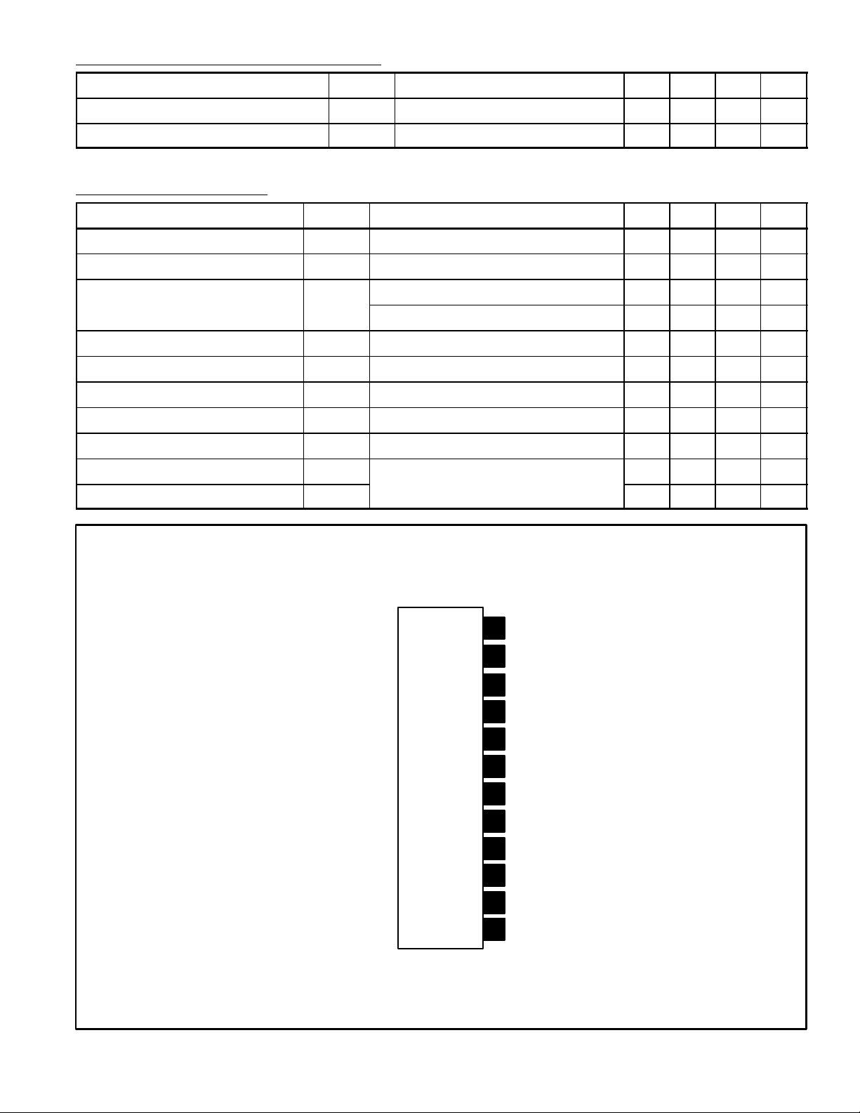
Pin Connection Diagram
(Front View)
12
11 Output 1
10
9
8
7
6
5
4
3
2
1
GND
Feedback
V
CC
47µF Cap
(+) Input 2
(+) Input 1
(–) Input 1
(–) Input 2
Bypass
Feedback
Output 2
 Loading...