

NTE NTE1377 Datasheet

NTE1377
Integrated Circuit
AF Power Amplifier, 6W/Channel
Features:
D Built–In 2 Channels (Dual) Enabling use in Stereo and Bridge Amplifier Applications
Dual: 6W x 2 Typ
Bridge: 19W Typ
D Minimum Number of External Parts Required
D Low Pop Noise during Power Supply ON/OFF and Good Starting Balance
D Good Ripple Rejection: 46dB Typ
D Good Channel Separation
D Low Residual Noise (R
D Low Distortion over a Wide Range of Low to High Frequencies
D Built–In Audio Muting Function
D Built–In Protectors:
a. Thermal Protection
b. Overvoltage, Surge Voltage Protection
c. Pin–to–Pin Short Protection
= 0)
g
Absolute Maximum Ratings:
Maximum Supply Voltage, V
(TA = +25°C unless otherwise specified)
max
CC
Quiescent (t = 30sec) 25V. . . . . . . . . . . . . . . . . . . . . . . . . . . . . . . . . . . . . . . . . . . . . . . . . . . . . . . . .
Operating 18V. . . . . . . . . . . . . . . . . . . . . . . . . . . . . . . . . . . . . . . . . . . . . . . . . . . . . . . . . . . . . . . . . . .
Surge Supply Voltage (t ≤ 0.2sec), V
surge 50V. . . . . . . . . . . . . . . . . . . . . . . . . . . . . . . . . . . . . . . . . .
CC
Allowable Power Dissipation (TC = +75°C), Pdmax 15W. . . . . . . . . . . . . . . . . . . . . . . . . . . . . . . . . . . . .
Thermal Resistance, Junction to Case, R
Operating Temperature Range, T
Storage Temperature Range, T
opr
stg
Recommended Operating Conditions:
Recommended Supply Voltage, V
Load Resistance, R
L
CC
Θ
JC
(TA = +25°C unless otherwise specified)
–20° to +75°C. . . . . . . . . . . . . . . . . . . . . . . . . . . . . . . . . . . . . . . . .
–40° to +150°C. . . . . . . . . . . . . . . . . . . . . . . . . . . . . . . . . . . . . . . . . .
Dual 2Ω to 8Ω. . . . . . . . . . . . . . . . . . . . . . . . . . . . . . . . . . . . . . . . . . . . . . . . . . . . . . . . . . . . . . . . . . .
Bridge 4Ω to 8Ω. . . . . . . . . . . . . . . . . . . . . . . . . . . . . . . . . . . . . . . . . . . . . . . . . . . . . . . . . . . . . . . . .
3°C/W. . . . . . . . . . . . . . . . . . . . . . . . . . . . . . . . . . . . . . . . .
13.2V. . . . . . . . . . . . . . . . . . . . . . . . . . . . . . . . . . . . . . . . . . . . . . . .
Electrical Characteristics: (TA = +25°C, VCC = 13.2V, RL = 4Ω, f = 1kHz, Rg = 600Ω, with
100 x 100 x 1.5mm
Parameter Symbol Test Conditions Min Typ Max Unit
3
Al fin unless otherwise specified)
Quiescent Current I
CCO
Voltage Gain V
Gain Differential ∆V
Output Power
P
Dual
G
G
O
THD = 10%
– 100 200 mA
49.5 51.5 53.5 dB
– – 2 dB
5.0 6.0 – W
Bridge – 19 – W
Total Harmonic Distortion THD PO = 1W – 0.1 1.0 %
Input Resistance r
Output Noise Voltage V
i
Rg = 0 – 0.6 1.0 mV
no
– 30 – kΩ
Rg = 10kΩ – 1.0 2.0 mV
Ripple Rejection Ratio R
VR = 200mV, fR = 100Hz, Rg = 0 – 46 – dB
r
Channel Separation Ch Sep vo = 0dBm, Rg = 10kΩ 45 55 – dB
Muting Rejection ATT vo = 0dBm, VM = 9V – 40 – dB
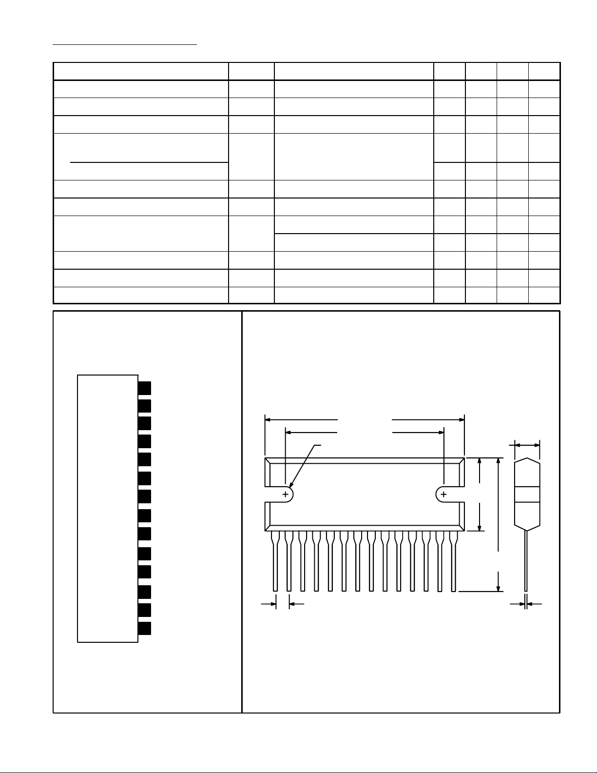
Pin Connection Diagram
(Front View)
14
Ch 1 Power GND
13
Ch 1 Bootstrap
12
Ch 1 Output
V
11
CC
10
Ch 2 Output
9
Ch 2 Bootstrap
8
Ch 2 Power GND
7
Ch 2 NF
6
Ch 2 Input
5
Decoupling
Audio Muting
4
3
Preamp GND
2
Ch 1 Input
Ch 1 NF1
1.456 (37.0)
1.181 (30.0)
.156 (3.95) R
114
.100 (2.54)
.177 (4.5)
.527
(13.38)
.815
(20.7)
.015 (0.38)
 Loading...