

NTE NTE1331 Datasheet
NTE1331
Integrated Circuit
Module – Dual, Audio Power Amplifier,
25W/Channel, 2 Power Supplies Required
Absolute Maximum Ratings: (TA = +25°C unless otherwise specified)
Maximum Supply Voltage, V
Operating Case Temperature, T
Storage Temperature Range, T
Allowable Load Shorting Time (In appointed condition), t
max ±38V. . . . . . . . . . . . . . . . . . . . . . . . . . . . . . . . . . . . . . . . . . . . . . . . . .
CC
C
stg
s
+105°C. . . . . . . . . . . . . . . . . . . . . . . . . . . . . . . . . . . . . . . . . . . . . . . . . .
–30° to +105°C. . . . . . . . . . . . . . . . . . . . . . . . . . . . . . . . . . . . . . . . . .
2sec. . . . . . . . . . . . . . . . . . . . . . . . . . . . . . .
Recommended Operating Conditions:
Recommended Supply Voltage, V
Load Resistance, R
L
Electrical Characteristics:
CC
(TA = +25°C, VCC = ±28V, RL = 8Ω, Rg = 600Ω, VG = 40dB unless
(TA = +25°C unless otherwise specified)
otherwise specified)
Parameter Symbol Test Conditions Min Typ Max Unit
Quiescent Current I
Output Power P
Total Harmonic Distortion THD PO = 1W, f = 20Hz to 20kHz – – 0.08 %
Frequency Response f PO = 1W, +0, –3dB, f = 1kHz 10 to 100k Hz
Input Resistance r
CCO
O
i
THD = 0.08%, f = 20Hz to 20kHz 25 – – W
PO = 1W, f = 1kHz – 32 – kΩ
– – 120 mA
±26V. . . . . . . . . . . . . . . . . . . . . . . . . . . . . . . . . . . . . . . . . . . . . . . . .
8Ω. . . . . . . . . . . . . . . . . . . . . . . . . . . . . . . . . . . . . . . . . . . . . . . . . . . . . . . . . . . . . . . . .
Pin Connection Diagram
(Front View)
Rt Ch Input
16
Rt Ch
15
Feedback
GND
14
13
Rt Ch Bias
12
(–) V
Rt Ch
11
Feedback
Rt Ch Output
10
(+) V
9
(+) V
8
7 Lt Ch Output
Lt Ch
6
Feedback
5
(–) V
Lt Ch Bias
4
3 GND
Lt Ch
2
Feedback
1
Lt Ch Input
CC
CC
CC
CC
2
2
1
1
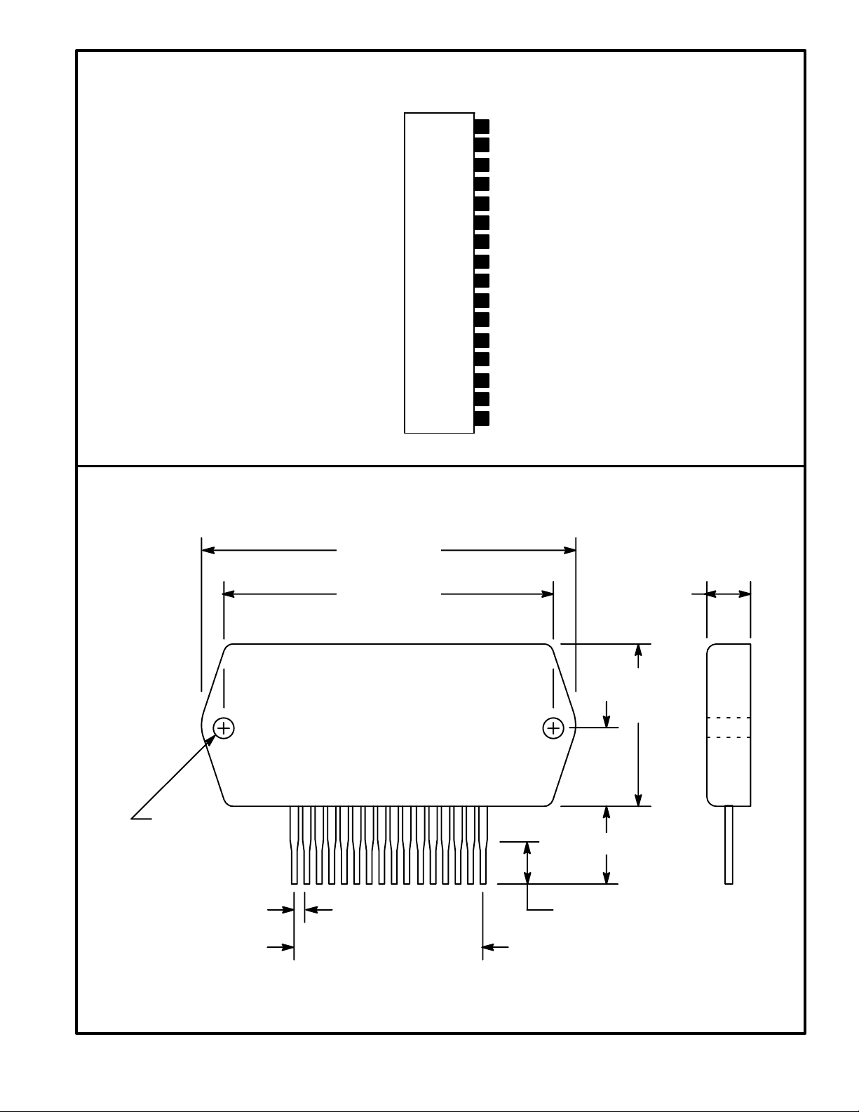
.135 (3.45)
Dia (2 Holes)
3.071 (90.7)
2.756 (70.0)
.315 (8.0)
1.733
(44.0)
.866
(22.0)
116
.492 (12.5)
.100 (2.54)
.200 (5.08) Min
1.500 (38.1)
 Loading...