

NTE NTE1295 Datasheet

NTE1295
Integrated Circuit
TV Signal Processor
Description:
The NTE1295 is an integrated circuit in an 18–Lead DIP type package designed for color TV deflection signal processing circuit. It can be operated with 12V power supply and is suitable for compact
and medium–sized color TV sets.
Features:
D Built–In Vertical Deflection Driver Circuit
D Incorporating Vertical and Horizontal Oscillator Circuit, Operations Highly Stable Against
Changes in Supply Voltage and Temperature.
D Highly Stable Synchronous Separation Circuit Against Noise
D Built–In High Tension Protector Circuit (X–Ray Protection)
D 12V Supply Voltage Operation.
Absolute Maximum Ratings
: (TA = +25°C, Note 1 unless otherwise specified)
Supply Voltage
V
7–8
V
15–8
Circuit Voltage
V
1–8
V
V
V
V
. . . . . . . . . . . . . . . . . . . . . . . . . . . . . . . . . . . . . . . . . . . . . . . . . . . . . . . . . . . . . . . . . .
10–8
. . . . . . . . . . . . . . . . . . . . . . . . . . . . . . . . . . . . . . . . . . . . . . . . . . . . . . . . . . . . . . . . . .
12–8
17–8
18–8
Supply Current
I
7
I
15
Circuit Current
I
2
I
3
I
4
I
5
I
6
I
9
I
12
I
13
Power Dissipation, P
Operating Ambient Temperature Range, T
Storage Temperature Range, T
D
opr
stg
Note 1. and are flow–in and flow–out currents to/from the circuit, respectively.
10.5V. . . . . . . . . . . . . . . . . . . . . . . . . . . . . . . . . . . . . . . . . . . . . . . . . . . . . . . . . . . . . . . . . . . . . .
14.4V. . . . . . . . . . . . . . . . . . . . . . . . . . . . . . . . . . . . . . . . . . . . . . . . . . . . . . . . . . . . . . . . . . . . .
0 to 10V. . . . . . . . . . . . . . . . . . . . . . . . . . . . . . . . . . . . . . . . . . . . . . . . . . . . . . . . . . . . . . . . . . . .
0 to V
0 to V
15–8
15–8
–0.6 to 6.0V. . . . . . . . . . . . . . . . . . . . . . . . . . . . . . . . . . . . . . . . . . . . . . . . . . . . . . . . . . . . . . . .
–3 to +2V. . . . . . . . . . . . . . . . . . . . . . . . . . . . . . . . . . . . . . . . . . . . . . . . . . . . . . . . . . . . . . . . . .
15mA. . . . . . . . . . . . . . . . . . . . . . . . . . . . . . . . . . . . . . . . . . . . . . . . . . . . . . . . . . . . . . . . . . . . . . . . .
20mA. . . . . . . . . . . . . . . . . . . . . . . . . . . . . . . . . . . . . . . . . . . . . . . . . . . . . . . . . . . . . . . . . . . . . . . .
–3 to +3mA. . . . . . . . . . . . . . . . . . . . . . . . . . . . . . . . . . . . . . . . . . . . . . . . . . . . . . . . . . . . . . . . . . . .
–5 to 0mA. . . . . . . . . . . . . . . . . . . . . . . . . . . . . . . . . . . . . . . . . . . . . . . . . . . . . . . . . . . . . . . . . . . . .
–5 to +5mA. . . . . . . . . . . . . . . . . . . . . . . . . . . . . . . . . . . . . . . . . . . . . . . . . . . . . . . . . . . . . . . . . . . .
–1 to +1mA. . . . . . . . . . . . . . . . . . . . . . . . . . . . . . . . . . . . . . . . . . . . . . . . . . . . . . . . . . . . . . . . . . . .
–20 to 0mA. . . . . . . . . . . . . . . . . . . . . . . . . . . . . . . . . . . . . . . . . . . . . . . . . . . . . . . . . . . . . . . . . . . .
–15 to 0mA. . . . . . . . . . . . . . . . . . . . . . . . . . . . . . . . . . . . . . . . . . . . . . . . . . . . . . . . . . . . . . . . . . . .
–1 to +150mA. . . . . . . . . . . . . . . . . . . . . . . . . . . . . . . . . . . . . . . . . . . . . . . . . . . . . . . . . . . . . . . . .
0 to 40mA. . . . . . . . . . . . . . . . . . . . . . . . . . . . . . . . . . . . . . . . . . . . . . . . . . . . . . . . . . . . . . . . . . . .
450mW. . . . . . . . . . . . . . . . . . . . . . . . . . . . . . . . . . . . . . . . . . . . . . . . . . . . . . . . . .
–20° to +70°C. . . . . . . . . . . . . . . . . . . . . . . . . . . . . . . . . .
–55° to +150°C. . . . . . . . . . . . . . . . . . . . . . . . . . . . . . . . . . . . . . . . . .
Electrical Characteristics: (TA = +25°C unless otherwise specified)
Parameter Symbol Test Conditions Min Typ Max Unit
Circuit Current I
Protector Operating Voltage V
Oscillation Starting Voltage
(V O
Vertical Oscillation Frequency f
fVO Change with Supply Voltage ∆fVO/V
Pulse Width (V Osc) t V
Vertical Pull–In Range f
Vertical Sawtooth Wave
Amplification
fVO Change with Ambient
Temperature
v
Change with Ambient
(saw)
Temperature
Vertical Output Tr Drive Current I
Oscillation Starting Voltage
(H O
Horizontal Oscillation Frequency f
fHO Change with Supply Voltage ∆fHO/V
Pulse Width Duty Ratio (H Osc) t V
fHO Control Sensitivity b IO = ±100mA 19 21 23 Hz/µA
sc
sc
)
)
7
I
15
5–8
V
OSC–SfVO
VO
VP
v
(saw)
∆fVO/TATA = –20° to +70°C, Note 2 –220 –170 0 ppm/°C
∆v
(saw)/T
9
V
OSC–SfHO
HO
Apply 12V with 240Ω to Pin7 7.5 11.2 15.0 mA
V
= 12V 15.5 23.0 32.0 mA
15–8
Apply 12V with 240Ω to Pin7 0.64 0.70 0.76 V
= 40 to 70Hz, 1.0V
V
= 12V 53 55 58 Hz
CC1
CCfVO|9.6V
R
R
A TA = –20° to +70°C, Note 2 – – 30 mV
1.4V
V
CCfHO|13V
to f
VO|14.4V
= 12V 500 600 820 µs
CC1
= 10.93kΩ, (fVO = 48 ±1.5Hz) – – 50 Hz
OSC
= 26.4kΩ 1.8 2.0 2.2 V
SAW
= 10 to 20kHz,
or More (V
P–P
= 12V 15.0 15.6 16.25 kHz
CC2
to fH
O|10V
= 12V 32.0 36.0 39.5 %
CC2
or More – – 6.2 V
P–P
0 0.93 1.3 Hz
– – 7.5 mA
– – 6 V
= 6.5V)
CC2
0 25 45 Hz
P–P
P–P
/°C
fHO Change with Ambient
Temperature
AFC Loop Gain f
∆fHO/TATA = –20° to +70°C, Note 2 –210 –100 0 ppm/°C
Note 2. Design reference value.
Horiz Sawtooth
Horiz Hold
Horiz Driver
Vert Output
AFC
m x b 5800 7700 9600 Hz/rad
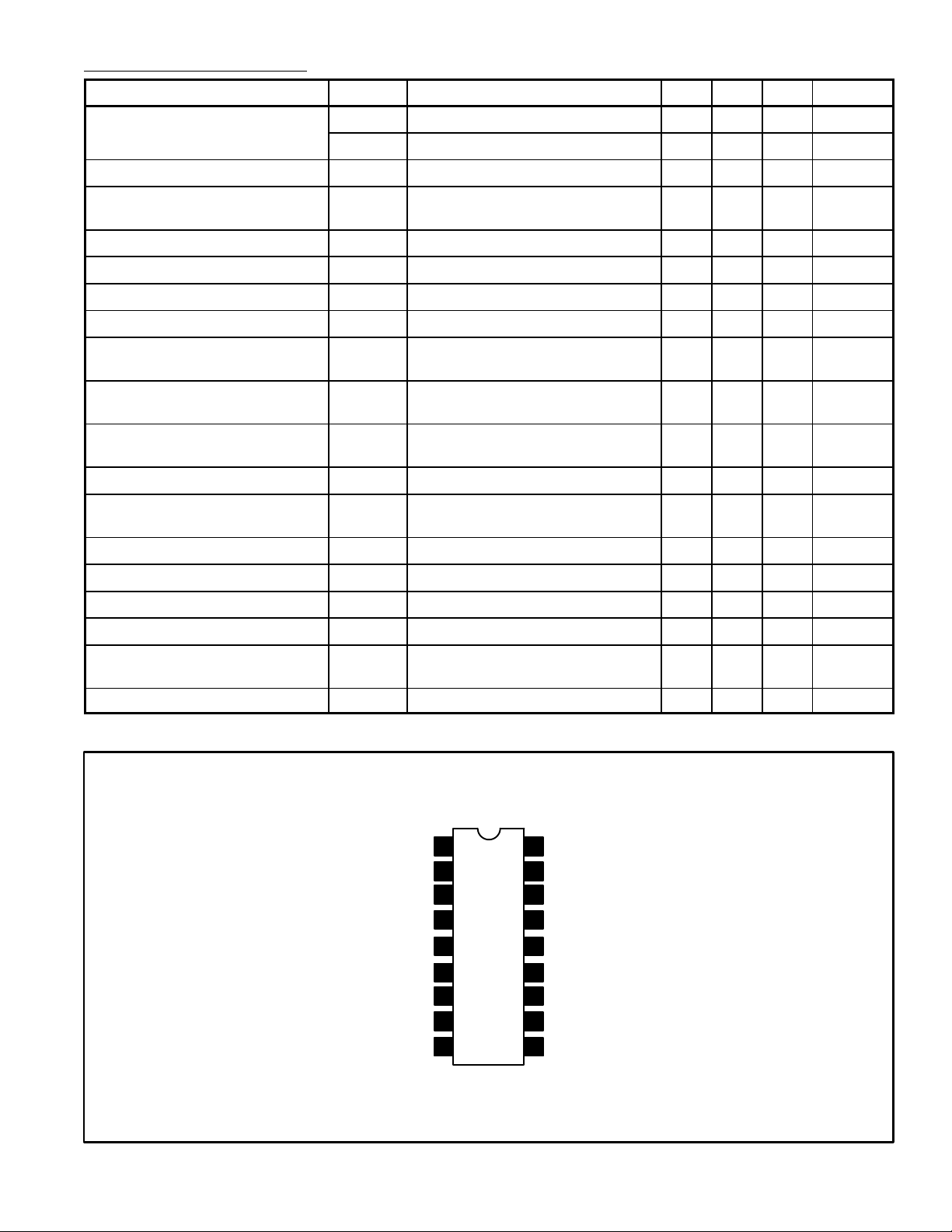
Pin Connection Diagram
1
Filter
2
3
Bypass
4
5Protector Input
6
7Voltage Regulator
8GND
9 10
18
Video Input
17
Noise Detector
16
Horiz Sync Output
V
15
CC
14 Bypass
13 Vert Hold
Vert Height
12
Vert Ramp Generator
11
Vert Driver Input
 Loading...