

NTE NTE1268 Datasheet
NTE1268
Integrated Circuit
DC Servo Circuit for VCR
Description:
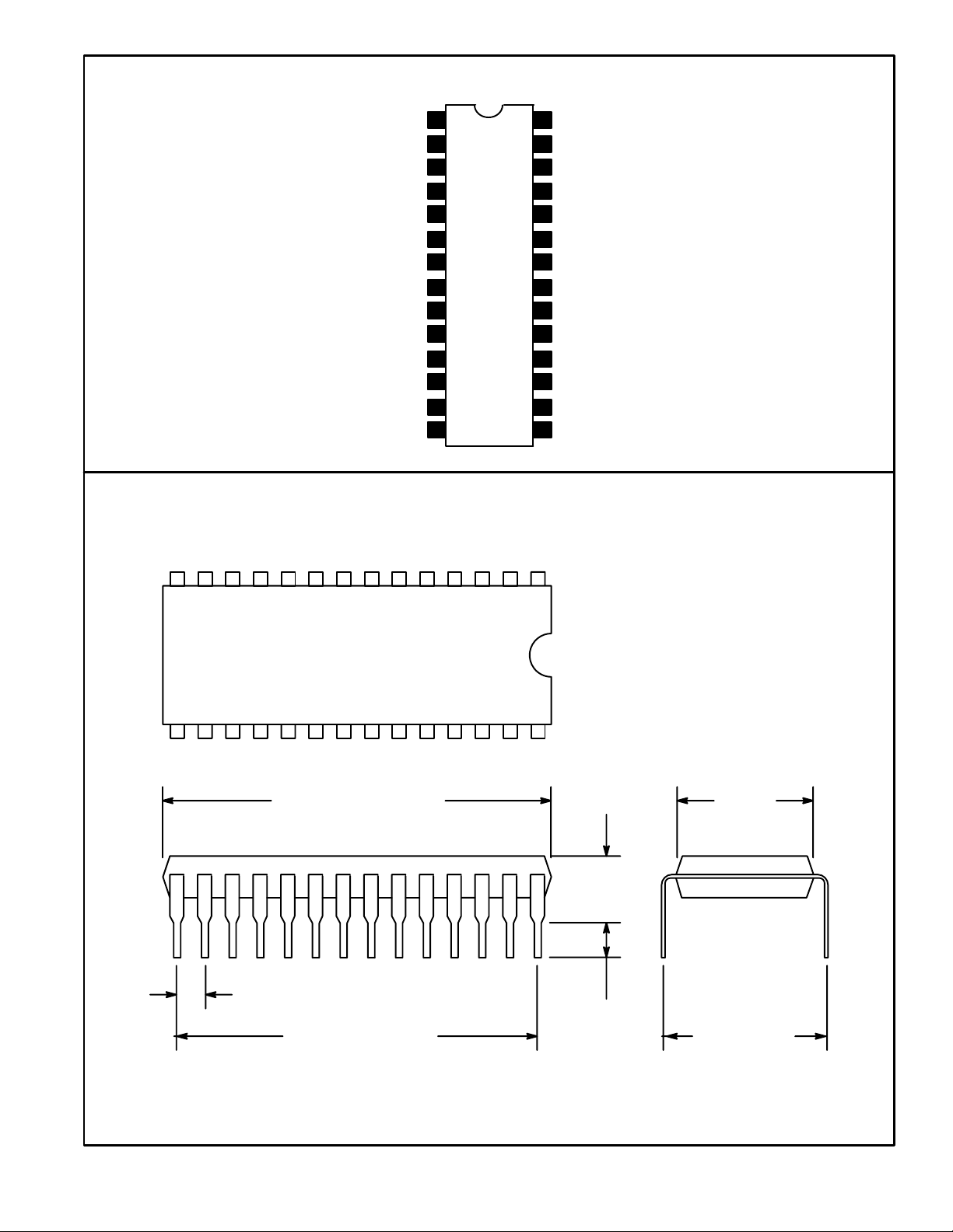
The NTE1268 is an integrated circuit in a 28–Lead DIP type package designed for DC Servo Control
Circuits in VCR’s.
Absolute Maximum Ratings
Supply Voltage (V
Power Dissipation, P
5–24
), V
D
: (TA = +25°C unless otherwise specified)
CC
Operating Temperature Range, T
Storage Temperature Range, T
Electrical Characteristics
Parameter Symbol Test Conditions Min Typ Max Unit
Total Circuit Current I
Trapezoidal Reference Voltage V
Output Voltage
FF–II
Trapezoidal I V
Trapezoidal II V
S & H–I V
S & H–II V
Gate–II V
Input Sensitivity
MM
Trapeziodal V
Gate V
S & H V
DET–I V
DET–II V
FG V
FF V
stg
: (TA = +25°C, VCC = 12V unless otherwise specified)
16–24
V
23–24
17–24
17–24
12–24
12–24
10–24
V
22–24
15–24
is(14)
is(28)
is(25)
opr
5–2
7–24
is(2)
is(4)
14.4V. . . . . . . . . . . . . . . . . . . . . . . . . . . . . . . . . . . . . . . . . . . . . . . . . . . . . . .
640mW. . . . . . . . . . . . . . . . . . . . . . . . . . . . . . . . . . . . . . . . . . . . . . . . . . . . . . . . . .
–20° to +70°C. . . . . . . . . . . . . . . . . . . . . . . . . . . . . . . . . . . . . . . . .
–40° to +150°C. . . . . . . . . . . . . . . . . . . . . . . . . . . . . . . . . . . . . . . . . .
23 31 41 mA
0.77 1.0 1.2 V
10.0 10.9 – V
2.4 3.0 3.6 V
11.0 11.9 – V
– 240 500 mV
8.0 8.8 – V
9.0 10.0 – V
3.5 – – V
4 – – V
3.5 – – V
f = 30Hz, PW = 100µs 1.5 – – V
400Hz, 1/2 Sampling Sine Wave, td = 1ms 50 – – mV
50 – – mV
f = 400Hz 100 – – mV
f = 30Hz, Rectangular Wave 3 – – V
O–P
O–P
O–P
O–P
O–P
O–P
P–P
O–P
Pin Connection Diagram
Ripple Filter
Detector 2 Input
Detector Time Constant
FG Amp Input
V
CC
Flip–Flop Output
Gate Time Constant
Ripple Filter
Motor Phase Signal Output
Bypass
Timing Signal Input
1
2
3
4
5
6
7Gate Input
8
9Gate Time Constant
11
12
13
14
28
Detector 1 Input
Detector Time Constant
27
Jumper to Pin22 & Pin25
26
25 Jumper to Pin22 & Pin26
GND Return
24
To Head Switch
23
22
Jumper to Pin25 & Pin26
21 Multi Time Constant
Multi Time Constant
20
GND10Motor Speed Signal Output
19
18
S & H Signal Source
17 Bypass
16 Resistive Constant
15 Timing Reference Signal
14 1
15 28
1.469 (37.32)
Max
.100 (2.54)
1.300 (33.02)
.250
(6.35)
.122
(3.1)
Min
.540
(13.7)
.600 (15.24)
 Loading...