

NTE NTE1266 Datasheet
NTE1266
Integrated Circuit
Color AGC Circuit for VCR
Absolute Maximum Ratings: (TA = +25°C unless otherwise specified)
Supply Voltage (V
Supply Current, I
Power Dissipation, P
Operating Temperature Range, T
Storage Temperatue Range, T
2–12
CC
D
), V
CC
opr
stg
14.4V. . . . . . . . . . . . . . . . . . . . . . . . . . . . . . . . . . . . . . . . . . . . . . . . . . . . . . .
42.5mA. . . . . . . . . . . . . . . . . . . . . . . . . . . . . . . . . . . . . . . . . . . . . . . . . . . . . . . . . . . . .
540mW. . . . . . . . . . . . . . . . . . . . . . . . . . . . . . . . . . . . . . . . . . . . . . . . . . . . . . . . . .
–20° to +70°C. . . . . . . . . . . . . . . . . . . . . . . . . . . . . . . . . . . . . . . . .
–40° to +150°C. . . . . . . . . . . . . . . . . . . . . . . . . . . . . . . . . . . . . . . . . . .
Electrical Characteristics:
(VCC = 12V, TA = +25°C unless otherwise specified)
Parameter Symbol Test Conditions Min Typ Max Unit
Total Circuit Current I
Input Bias Voltage V
AGC Amp Output Voltage V
AGC Characteristics V
Burst Gate Level V
tot
13–12
O(AGC1)VCHROMA
O(AGC2)
V
O(AGC3)
(Burst)
–20dB 195 260 348 mV
+6dB 225 300 400 mV
V1 Sawtooth 3V
BM Carrier Suppression SC V3 = 133mV
Killer Amp Output Voltage G
Killer Operation Level K
KILLERV9–12
gate
= 142mV
DC measuring 1.1 1.4 1.7 V
= 225mV
P–P
, V5 = 52mV
rms
rms
26.5 33.0 40.7 mA
– 1.85 – V
(0dB) 218 290 390 mV
P–P
, f = 10kHz 1.3 1.65 1.9 V
rms
35 45 – dB
1.1 1.37 1.64 V
(DC)
P–P
P–P
P–P
P–P
Pin Connection Diagram
Burst Gate Input
Balance Modulator Input
Bypass
Balance Modulator Input
Balance Modulator Output
Level Control
1
2
V
CC
3
4
5
6Killer Amp Input
7
8
16 9
16
Burst Gate Output
15
Burst Gate Input
14
AGC Detector
13
AGC Input
12
GND
AGC Output
11
Killer Amp Output
10
Killer Amp Input
9
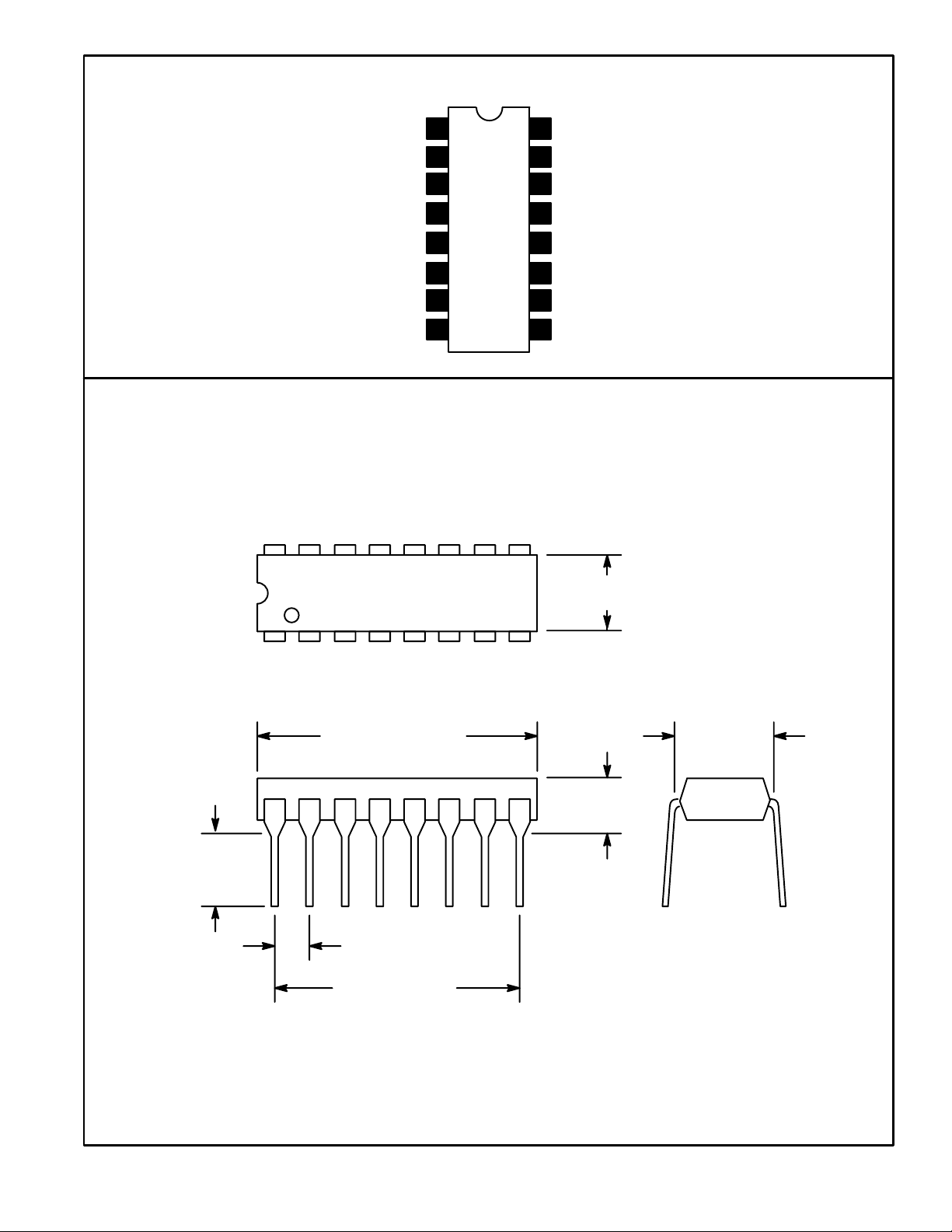
.245
(6.22)
Min
.260 (6.6) Max
18
.785 (19.9) Max
.300 (7.62)
.200 (5.08)
Max
.100 (2.54)
.700 (17.7)
 Loading...