

NTE NTE1214 Datasheet

NTE1214
Integrated Circuit
AM Tuner System
Description:
The NTE1214 is a high integrated circuit in a 16–Lead DIP type package designed for use in the AM
system of high grade receivers. This device contains most of the functions needed for AM receiving.
Functions:
D RF Amplifier
D Frequency Counter
D IF Amplifier
Features:
D RF Amplifier Stage:
Good quieting sensitivity by means of low noise transistors and cascade connecting.
D Frequency Converter Stage:
Splendid spurious characteristics by means of reduction of high frequency distortion in local
oscillation and differential mixer.
D IF Amplifier Stage:
Reasonable distortion by wide output dynamic range.
D Detector Stage:
Low distortion even at deep modulation considering diagonal clip or negative clip.
D AGC Stage:
Wide AGC range and good large input signal characteristics by AGC’d IF and RF amplifier
stage.
D Signal Meter Driving Stage:
Excellent linearity to input signal.
D Others:
Stabilized biasing against supply voltage drifting over all stages. Particularly superior compensation circuit in IF amplifier. Less deterioration of gain, detector output, and distortion in
low supply voltage range in order to get wide supply voltage range (7V* to 16V).
D Detector
D AGC
D Signal Meter Driving
* Needs to vary peripheral parts and its value of RF and local oscillator stage for the purpose of low
supply voltage operation.
Absolute Maximum Ratings: (TA = +25°C unless otherwise specified)
Maximum Supply Voltage (Pin3, Pin11), V
Output Voltage (Pin4, Pin5), v
Input Voltage (Pin2), v
i
o
Supply Current (Pin3, Pin4, Pin5, Pin11), I
Flow–Out Current (Pin15), I
Allowable Power Dissipation (T
Operating Temperature Range, T
Storage Temperature Range, T
15
≤ +70°C), PDmax 450mW. . . . . . . . . . . . . . . . . . . . . . . . . . . . . . . . . .
A
opr
stg
max 16V. . . . . . . . . . . . . . . . . . . . . . . . . . . . . . . . . . . . . . .
CC
CC
24V. . . . . . . . . . . . . . . . . . . . . . . . . . . . . . . . . . . . . . . . . . . . . . . . . . . . . . .
0 to 4V. . . . . . . . . . . . . . . . . . . . . . . . . . . . . . . . . . . . . . . . . . . . . . . . . . . . . . . . . . .
30mA. . . . . . . . . . . . . . . . . . . . . . . . . . . . . . . . . . . . . . . .
2mA. . . . . . . . . . . . . . . . . . . . . . . . . . . . . . . . . . . . . . . . . . . . . . . . . . . . . . .
–20° to +70°C. . . . . . . . . . . . . . . . . . . . . . . . . . . . . . . . . . . . . . . . .
–40° to +125°C. . . . . . . . . . . . . . . . . . . . . . . . . . . . . . . . . . . . . . . . . .
Recommended Operating Conditions:
Recommended Supply Voltage, V
Electrical Characteristics:
CC
(TA = +25°C, VCC = 12V, f = 1000kHz, fm = 400Hz unless otherwise
(TA = +25°C unless otherwise specified)
12V. . . . . . . . . . . . . . . . . . . . . . . . . . . . . . . . . . . . . . . . . . . . . . . . . .
specified)
Parameter Symbol Test Conditions Min Typ Max Unit
Current Dissipation I
Detector Output v
Signal–to–Noise Ratio S/N Input 23dB, 30% MOD 16 20 – dB
Total Harmonic Distortion THD Input 80dB, 80% MOD – 0.5 1.0 %
Signal Meter Driving Output V
CC
SM
No Input – 16 23 mA
Input 23dB, 30% MOD –27.5 –23.0 – dBm
o
Input 80dB, 30% MOD –16 –13 –10 dBm
Input 80dB, 30% MOD 49 53 – dB
Input 107dB, 30% MOD – 0.3 1.0 %
Input 107dB, 30% MOD 0.40 0.44 0.48 V
Note 1. 0dBm is defined as 0.775V, and in IF circuit 0dB is 1µV of IHF input at the use of IHF dummy
antenna.
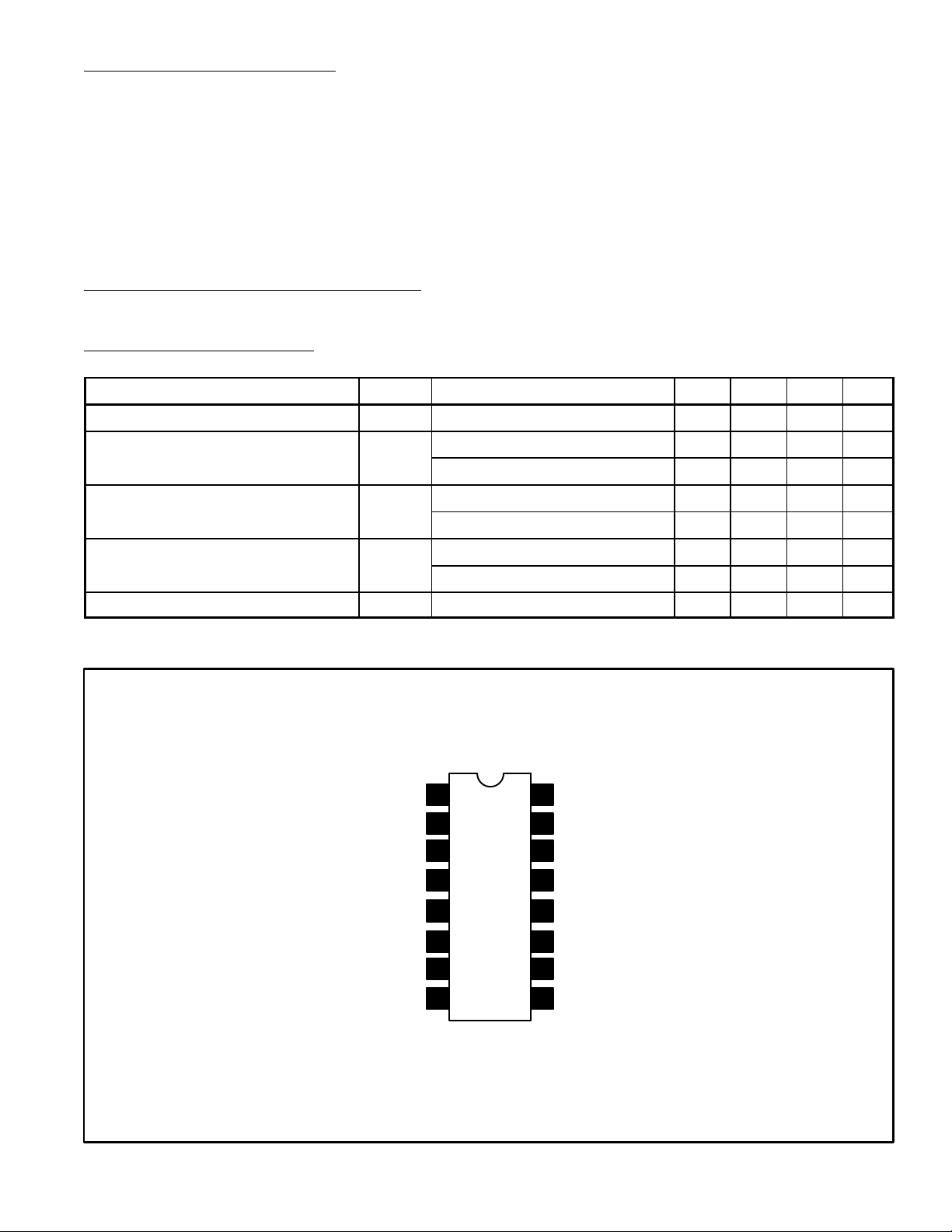
Pin Connection Diagram
RF Amp DC Bypass
RF Tune
Converter V
CC
RF Amp Output
Converter Output
OSC Tank Circuit
Converter Input
rd
IF Amp Input
3
1
2
3
4
5
6
7
8
16
RF Amp DC Bypass
15
Tune Meter Output
14
AGC Bypass
rd
13
3
IF Amp Input Tune
12
Detector Output
11
IF System V
10
DC Return (Substrate)
9
2nd IF Amp Output
CC
 Loading...