

NTE NTE107 Datasheet
NTE107
Silicon NPN Transistor
UHF Oscillator for Tuner
Description:
The NTE107 is a silicon NPN planar epitaxial transistor in a TO92 type package designed specifically
for high frequency applications. This device is s uitable for use as an oscillator in UHF t elevision tuners.
Absolute Maximum Ratings:
Collector–Base Voltage, V
Collector–Emitter Voltage, V
Emitter–Base Voltage, V
Collector Current, I
EBO
C
Total Power Dissipation (T
(TA = +25°C unless otherwise specified)
CBO
CEO
= +25°C), P
A
T
Derate above +25°C 2.67mW/°C. . . . . . . . . . . . . . . . . . . . . . . . . . . . . . . . . . . . . . . . . . . . . . . . . . .
Operating Junction Temperature, T
Storage Temperature Range, T
J
stg
Lead temperature (During Soldering, 1/16” ±1/32” from case, 10sec), T
(T
Electrical Characteristics:
Parameter Symbol Test Conditions Min Typ Max Unit
Static Characteristics
Collector–Base Breakdown Voltage V
Collector–Emitter Breakdown Voltage V
Emitter–Base Breakdown Voltage V
Collector Cutoff Current I
Emitter Cutoff Current I
Forward Current Transfer Ratio h
Collector Saturation Voltage V
= +25°C unless otherwise specified)
A
(BR)CBOIC
(BR)CEOICEO
(BR)EBOIE
CBO
EBO
FE
CE(sat)IC
= 100µA 30 – – V
= 3mA, Note 1 12 – – V
= 100µA 3 – – V
VCB = 15V, IE = 0 – – 0.5 µA
VEB = 2V, IC = 0 – – 0.5 µA
VCE = 10V, IC = 8mA 20 75 –
= 10mA, IB = 1mA – – 0.6 V
30V. . . . . . . . . . . . . . . . . . . . . . . . . . . . . . . . . . . . . . . . . . . . . . . . . . . . . . .
12V. . . . . . . . . . . . . . . . . . . . . . . . . . . . . . . . . . . . . . . . . . . . . . . . . . . . . .
3V. . . . . . . . . . . . . . . . . . . . . . . . . . . . . . . . . . . . . . . . . . . . . . . . . . . . . . . . . .
25mA. . . . . . . . . . . . . . . . . . . . . . . . . . . . . . . . . . . . . . . . . . . . . . . . . . . . . . . . . . . . . .
200mW. . . . . . . . . . . . . . . . . . . . . . . . . . . . . . . . . . . . . . . . . .
+100°C. . . . . . . . . . . . . . . . . . . . . . . . . . . . . . . . . . . . . . . . . . . . . . .
–55° to +125°C. . . . . . . . . . . . . . . . . . . . . . . . . . . . . . . . . . . . . . . . . .
L
+260°C. . . . . . . . . . . . . . .
Note 1. Pulse test: Pulse Width = 1µs, Duty Cycle = 1%.
Electrical Characteristics (Cont’d): (TA = +25°C unless otherwise specified)
Parameter Symbol Test Conditions Min Typ Max Unit
Dynamic Characteristics
Current Gain–Bandwidth Product f
Output Capacitance C
Noise Figure NF IC = 1mA, VCB = 6V, f = 60MHz,
T
ob
IC = 5mA, VCE = 10V, f = 100MHz 700 – 2100 MHz
VCE = 10V, IE = 0, f = 1MHz 0.8 – 1.5 pF
R
= 400Ω
G
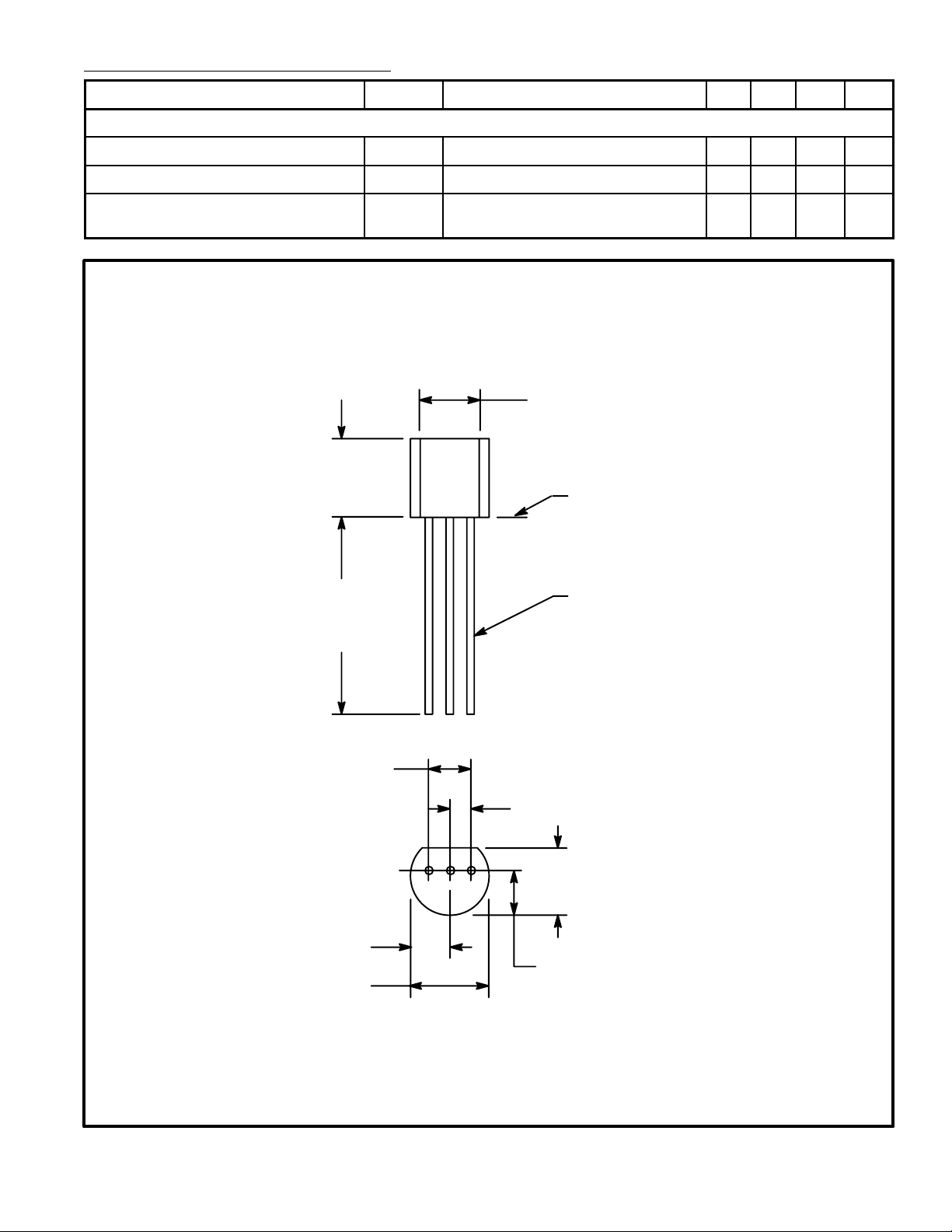
.135 (3.45) Min
.210
(5.33)
Max
.500
Seating Plane
.021 (.445) Dia Max
(12.7)
Min
– 4.0 6.5 dB
.100 (2.54)
.105 (2.67) Max
.205 (5.2) Max
E C B
.050 (1.27)
.165
(4.2)
Max
.105 (2.67) Max
 Loading...