

NTE NTE1041 Datasheet
NTE1041
Integrated Circuit
FM IF Amplifier
Absolute Maximum Ratings: (TA = +25°C unless otherwise specified)
Supply Volatge (Note 1), V
Power Dissipation, P
T
Operating Temperature Range, T
Storage Temperature Range, T
Note 1. Value at VEE = 0V.
Electrical Characteristics: (VCC = 9V, TA = +25°C unless otherwise specified)
Parameter Symbol Test Conditions Min Typ Max Unit
CC
opr
stg
16V. . . . . . . . . . . . . . . . . . . . . . . . . . . . . . . . . . . . . . . . . . . . . . . . . . . . . . . .
300mW. . . . . . . . . . . . . . . . . . . . . . . . . . . . . . . . . . . . . . . . . . . . . . . . . . . . . . . . . . . .
–20° to +70°C. . . . . . . . . . . . . . . . . . . . . . . . . . . . . . . . . . . . . . . . .
–55° to +125°C. . . . . . . . . . . . . . . . . . . . . . . . . . . . . . . . . . . . . . . . . .
Circuit Current I
Power Consumption P
Power Gain PG
Muting Attenuation M
Input Admittance Y
Reverse Transadmittance Y
Forward Transadmittance Y
Output Admittance Y
T
att
11
12
21
22
T
f = 10.7MHz
1.2 2.2 3.5 mA
– 50 80 mW
26 32 – dB
50 62 – dB
– 0.5 +j0.5 – mmhos
– 0.01 + j0.0002 – mmhos
– –37 + j10. 5 – mmhos
– 0.04 + j0.23 – mmhos
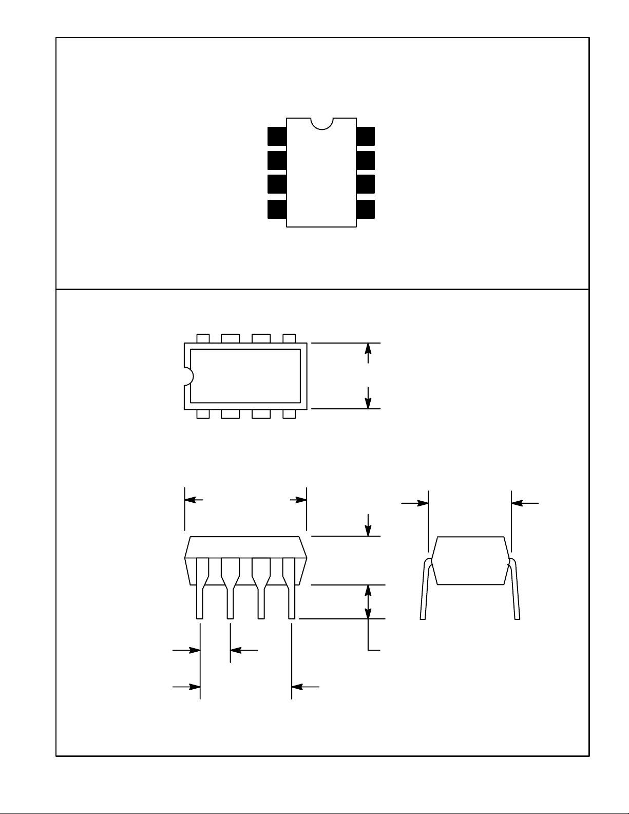
Pin Connection Diagram
GND
N.C.
Input
Input
1
2
3
4
8
7
6
5
85
.256 (6.52) Max
14
N.C.
Bias
V
CC
Output
.393 (10.0)
Max
.300 (7.62)
.300 (7.62)
.150
(3.81)
.070 (1.77) Min.100 (2.54)
 Loading...