

Page 1
4100FS.book Page 1 Tuesday, July 8, 2003 4:35 PM
USER'S GUIDE
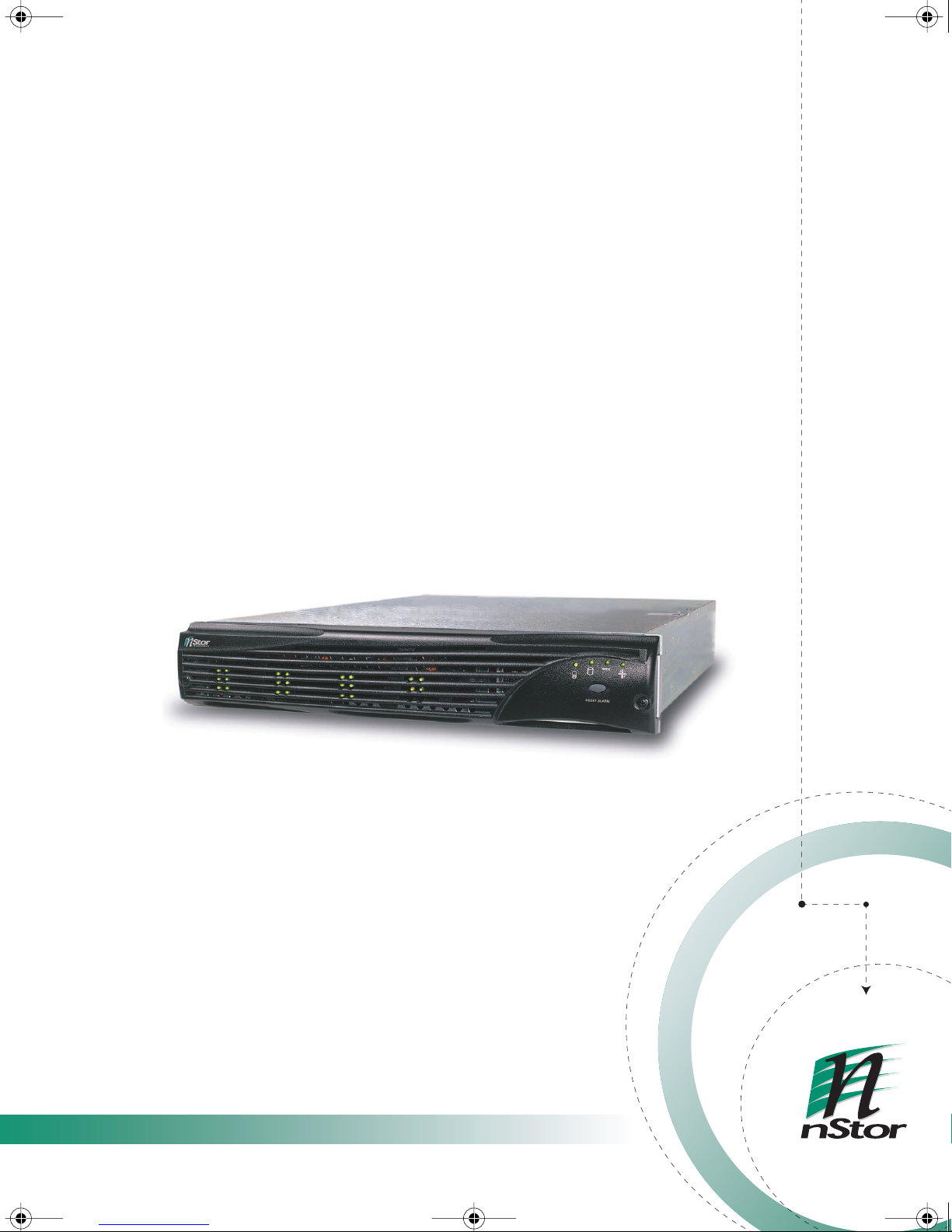
NexStor® 4100FS
STORAGE SYSTEMS
Page 2

4100FS.book Page 2 Tuesday, July 8, 2003 4:35 PM
Page 3

4100FS.book Page 3 Tuesday, July 8, 2003 4:35 PM
USER'S GUIDE
NexStor® 4100FS
STORAGE SYSTEMS
Page 4
4100FS.book Page 4 Tuesday, July 8, 2003 4:35 PM
nStor Corporation, Inc.
Restricted Rights and Liability
No part of this manual may be reproduced, stored in a retrieval system, or transmitted, in any form or by any
means, electronic, mechanical, recording, or otherwise, in whole or part, without prior written permission from
nStor Corporation, Inc.
nStor Corporation, Inc. shall not be liable for any damages or for the loss of any information resulting from the
performance or use of the information contained herein. Your rights to the software are governed by the license
agreement included with any accompanying software. nStor Corporation reserves the right to periodically revise
this manual without notice. Product features and specifications described are subject to change without notice.
For Regulatory information, see Appendix C.
Copyright
nStor
Corporation
, Inc.
6190 Corte Del Cedro Road
Carlsbad, CA 92009
Copyright © 2003 nStor Corporation, Inc. All Rights Reserved.
nStor, AdminiStor, NexStor, the NexStor logo, and the nStor logo are trademarks or registered trademarks of nStor
Corporation, Inc.
Other company and product names herein may be trademarks or registered trademarks of their respective
companies.
Agency Notes
WARNING: Drives and controller/adapter cards described in this manual should only be installed in UL-listed and CSA
certified computers that give specific instructions on the installation and removal of accessory cards (refer to your
computer installation manual for proper instructions).
ATTENTION: Les lecteurs et cartes contrôleurs décrits ici ne doivent être montés que sur des ordinateurs homologués (UL et
CSA) et livrés avec des manuels contenant les instructions d’installation et de retrait des accessoires. Reportezvous au manuel d’installation de votre ordinateur.
SERVICE NOTE: Remove the power cables prior to servicing this equipment.
!
Page 5

4100FS.book Page i Tuesday, July 8, 2003 4:35 PM
Contents
About this Manual . . . . . . . . . . . . . . . . . . . . . . . . . . . . . . . . . . . . . v
Welcome . . . . . . . . . . . . . . . . . . . . . . . . . . . . . . . . . . . . . . . . . . v
Features . . . . . . . . . . . . . . . . . . . . . . . . . . . . . . . . . . . . . . . . . . vi
1 Getting Started . . . . . . . . . . . . . . . . . . . . . . . . . . . . . . . . . . . . . . . . 1
At a Glance . . . . . . . . . . . . . . . . . . . . . . . . . . . . . . . . . . . . . . . . 2
Components . . . . . . . . . . . . . . . . . . . . . . . . . . . . . . . . . . . . . . . 3
Front Bezel . . . . . . . . . . . . . . . . . . . . . . . . . . . . . . . . . . . . . . . . 3
AC Power . . . . . . . . . . . . . . . . . . . . . . . . . . . . . . . . . . . . . . . . . 4
Cooling Fan Module . . . . . . . . . . . . . . . . . . . . . . . . . . . . . . . . . 5
SAF-TE Disk I/O Card . . . . . . . . . . . . . . . . . . . . . . . . . . . . . . . . 7
Host SCSI I/O Card . . . . . . . . . . . . . . . . . . . . . . . . . . . . . . . . . . 9
Fibre Channel Host I/O Card . . . . . . . . . . . . . . . . . . . . . . . . . . . 10
RAID Controllers . . . . . . . . . . . . . . . . . . . . . . . . . . . . . . . . . . . . 11
RS-232 Service Ports . . . . . . . . . . . . . . . . . . . . . . . . . . . . . . . . . 14
Control and Monitoring . . . . . . . . . . . . . . . . . . . . . . . . . . . . . . . 15
Status Indicator LEDs . . . . . . . . . . . . . . . . . . . . . . . . . . . . . . . . . 16
Drive LEDs . . . . . . . . . . . . . . . . . . . . . . . . . . . . . . . . . . . . . . . . 16
Audible Alarm . . . . . . . . . . . . . . . . . . . . . . . . . . . . . . . . . . . . . . 17
2 Theory of Controller Operation . . . . . . . . . . . . . . . . . . . . . . . . . . . . 19
Operating Modes Overview . . . . . . . . . . . . . . . . . . . . . . . . . . . . 19
Stand-Alone Mode . . . . . . . . . . . . . . . . . . . . . . . . . . . . . . . . . . . 21
Active-Active Mode . . . . . . . . . . . . . . . . . . . . . . . . . . . . . . . . . . 22
Active-Passive Mode . . . . . . . . . . . . . . . . . . . . . . . . . . . . . . . . . 27
Understanding Mirrored Operations . . . . . . . . . . . . . . . . . . . . . . 29
A Word about Clustering . . . . . . . . . . . . . . . . . . . . . . . . . . . . . . 30
Minimizing Downtime for Maximum Data Availability . . . . . . . . . 30
How Available are Clusters? . . . . . . . . . . . . . . . . . . . . . . . . . . . . 32
Application of Availability . . . . . . . . . . . . . . . . . . . . . . . . . . . . . 32
i
Page 6

4100FS.book Page ii Tuesday, July 8, 2003 4:35 PM
Table of Contents
3 Setup and Installation . . . . . . . . . . . . . . . . . . . . . . . . . . . . . . . . . . . 33
Overview . . . . . . . . . . . . . . . . . . . . . . . . . . . . . . . . . . . . . . . . . 33
Storage System Detailed Installation . . . . . . . . . . . . . . . . . . . . . . 34
Installing the Storage System Enclosure into the Rack Cabinet . . 34
Installing the Storage System into the Tower Stand . . . . . . . . . . 37
Completing the Installation . . . . . . . . . . . . . . . . . . . . . . . . . . . . 40
Enclosure Configuration . . . . . . . . . . . . . . . . . . . . . . . . . . . . . . 42
Topology Host Cabling . . . . . . . . . . . . . . . . . . . . . . . . . . . . . . . 57
Upgrades . . . . . . . . . . . . . . . . . . . . . . . . . . . . . . . . . . . . . . . . . 69
Powering On the Storage System . . . . . . . . . . . . . . . . . . . . . . . . 70
Powering Off the Storage System . . . . . . . . . . . . . . . . . . . . . . . . 70
4 SAN Solution Strategies . . . . . . . . . . . . . . . . . . . . . . . . . . . . . . . . . 71
Active-Active:Dual Port Mode for SAN . . . . . . . . . . . . . . . . . . . . 71
Active-Active:Single Port Mode for SAN . . . . . . . . . . . . . . . . . . . 76
SAN Configuration Not Supported . . . . . . . . . . . . . . . . . . . . . . . 80
True LUN Sharing . . . . . . . . . . . . . . . . . . . . . . . . . . . . . . . . . . . 80
5 Accessing the RAID Controllers . . . . . . . . . . . . . . . . . . . . . . . . . . . 81
Accessing the Disk Array Administrator Software/VT-100 . . . . . . 82
Menu System . . . . . . . . . . . . . . . . . . . . . . . . . . . . . . . . . . . . . . 84
Updating RAID Controller Firmware . . . . . . . . . . . . . . . . . . . . . 86
6 Monitoring Systems . . . . . . . . . . . . . . . . . . . . . . . . . . . . . . . . . . . . 89
Enclosure Component Monitoring . . . . . . . . . . . . . . . . . . . . . . . 89
Status Indicator LEDs . . . . . . . . . . . . . . . . . . . . . . . . . . . . . . . . 90
Drive LEDs . . . . . . . . . . . . . . . . . . . . . . . . . . . . . . . . . . . . . . . . 91
Drive Carrier LitePipes . . . . . . . . . . . . . . . . . . . . . . . . . . . . . . . 92
Audible Alarm . . . . . . . . . . . . . . . . . . . . . . . . . . . . . . . . . . . . . 92
One-Touch Annunciation . . . . . . . . . . . . . . . . . . . . . . . . . . . . . 95
Enclosure SAF-TE Monitoring . . . . . . . . . . . . . . . . . . . . . . . . . . 98
Enclosure Fan Speed Control . . . . . . . . . . . . . . . . . . . . . . . . . . . 100
SAFTE Commands Debug . . . . . . . . . . . . . . . . . . . . . . . . . . . . . 102
Uploading SAF-TE Controller Card Firmware . . . . . . . . . . . . . . . 103
7 Troubleshooting . . . . . . . . . . . . . . . . . . . . . . . . . . . . . . . . . . . . . . . 107
General Enclosure Problems . . . . . . . . . . . . . . . . . . . . . . . . . . . 107
Common SCSI Bus Problems . . . . . . . . . . . . . . . . . . . . . . . . . . . 107
Terminal Emulator and COM Port Problems . . . . . . . . . . . . . . . . 109
Host SCSI Channel Problems . . . . . . . . . . . . . . . . . . . . . . . . . . . 110
ii
Page 7

4100FS.book Page iii Tuesday, July 8, 2003 4:35 PM
Device SCSI Channel Problems . . . . . . . . . . . . . . . . . . . . . . . . . 110
Problems During Bootup . . . . . . . . . . . . . . . . . . . . . . . . . . . . . . 111
Controller Problems . . . . . . . . . . . . . . . . . . . . . . . . . . . . . . . . . . 112
Common Problems and Interpreting the LEDs . . . . . . . . . . . . . . 112
Warning and Error Events . . . . . . . . . . . . . . . . . . . . . . . . . . . . . 113
Warnings . . . . . . . . . . . . . . . . . . . . . . . . . . . . . . . . . . . . . . . . . 113
Errors . . . . . . . . . . . . . . . . . . . . . . . . . . . . . . . . . . . . . . . . . . . . 114
Disk Errors . . . . . . . . . . . . . . . . . . . . . . . . . . . . . . . . . . . . . . . . 115
Disk Channel Errors . . . . . . . . . . . . . . . . . . . . . . . . . . . . . . . . . . 116
8 Maintenance . . . . . . . . . . . . . . . . . . . . . . . . . . . . . . . . . . . . . . . . . . 119
Removing the Front Bezel . . . . . . . . . . . . . . . . . . . . . . . . . . . . . 119
Replacing the Cooling Fans . . . . . . . . . . . . . . . . . . . . . . . . . . . . 121
Replacing a Power Supply . . . . . . . . . . . . . . . . . . . . . . . . . . . . . 123
Replacing a Disk Drive . . . . . . . . . . . . . . . . . . . . . . . . . . . . . . . 125
Replacing the SAF-TE Disk I/O and Host SCSI I/O Card . . . . . . . 127
Replacing the Host I/O Card . . . . . . . . . . . . . . . . . . . . . . . . . . . 129
Replacing a RAID Controller . . . . . . . . . . . . . . . . . . . . . . . . . . . 132
Replacing a “Killed” Controller When in Active-Active/
Active-Passive Mode . . . . . . . . . . . . . . . . . . . . . . . . . . . . . . . . 133
Replacing the Enclosure . . . . . . . . . . . . . . . . . . . . . . . . . . . . . . . 134
Table of Contents
A Technical Information . . . . . . . . . . . . . . . . . . . . . . . . . . . . . . . . . . . 137
Specifications . . . . . . . . . . . . . . . . . . . . . . . . . . . . . . . . . . . . . . 137
B Port and Transceiver Information . . . . . . . . . . . . . . . . . . . . . . . . . . 141
VHD/CI SCSI Connectors . . . . . . . . . . . . . . . . . . . . . . . . . . . . . . 141
SAF-TE Service Port . . . . . . . . . . . . . . . . . . . . . . . . . . . . . . . . . . 144
RAID Controller Service Ports . . . . . . . . . . . . . . . . . . . . . . . . . . . 144
Null-Modem Cable . . . . . . . . . . . . . . . . . . . . . . . . . . . . . . . . . . 145
Optical SFP Transceiver . . . . . . . . . . . . . . . . . . . . . . . . . . . . . . . 146
C Regulatory Information . . . . . . . . . . . . . . . . . . . . . . . . . . . . . . . . . . 147
Compliance Information Statement . . . . . . . . . . . . . . . . . . . . . . . 147
FCC Class A Radio Frequency Interference Statement . . . . . . . . . 148
Class A Taiwanese Statement . . . . . . . . . . . . . . . . . . . . . . . . . . . 149
Class A Japanese Statement . . . . . . . . . . . . . . . . . . . . . . . . . . . . 149
CE Notice . . . . . . . . . . . . . . . . . . . . . . . . . . . . . . . . . . . . . . . . . 149
Power Cord Selection . . . . . . . . . . . . . . . . . . . . . . . . . . . . . . . . 150
Index . . . . . . . . . . . . . . . . . . . . . . . . . . . . . . . . . . . . . . . . . . . . . . . 151
iii
Page 8

4100FS.book Page iv Tuesday, July 8, 2003 4:35 PM
Table of Contents
iv
Page 9
4100FS.book Page v Tuesday, July 8, 2003 4:35 PM
Preface
About this Manual
Welcome
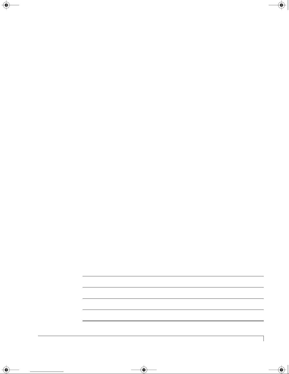
Congratulations on the purchase of your new NexStor 4100FS Series RAID
Storage System from nStor Corporation. The NexStor 4100FS Series is a very
high-performance fully fault-tolerant Fibre Channel-to-Ultra160 SCSI storage
system. It’s unique 2U design is optimized to fit in the compact space of today’s
data center rack enclosures and as a deskside tower system.
At its core is the
pluggable
1-inch high Ultra320 or Ultra160 disk drives
Ultra160 SCSI
storage enclosure which supports up to twelve hot
all in a 2U (3.47-inch) form
factor enclosure. Full component redundancy is provided through hot pluggable
cooling fan module and independent power supplies. RAID functionality is
provided through hot pluggable embedded
Fibre Channel-to-Ultra160 SCSI
RAID
Controllers. The NexStor 4100FS is available in two model configurations, a single
controller configuration designed for Stand-Alone topologies, or a dual controllers
configuration for Active-Active or Active-Passive topologies.
Product Identification
Storage Enclosure Number of Controllers Model of Controller
NexStor 4000S
NexStor 4110FS
NexStor 4120FS
0 JBOD
1 NexStor-Chaparral JFS224
2 NexStor-Chaparral JFS224
v
Page 10

4100FS.book Page vi Tuesday, July 8, 2003 4:35 PM
About this Manual
This user’s guide is your complete documentation to set up the storage system
hardware, add components, cable the storage system components, replace parts,
and diagnose/repair your system.
For information on the software control, management and configuration, refer to
one of the following: VT-100 Software Guide or the AdminiStor Software Guide.
Features
The NexStor 4100FS Series Storage Systems are designed for mission critical
applications requiring the highest performance with uncompromised data
reliability, such as mid-range and enterprise server storage. They maintain
exceptionally high throughput and are ideally suited for high bandwidth data
intensive applications, such as electronic commerce, digital video, CAD, seismic
research, digital pre-press, and 3-D imaging.
The following are major features of the NexStor
■
2 Gb Fibre Channel-to-Ultra160 RAID storage system enclosure.
■
Hot pluggable Fibre Channel-to-Ultra160 RAID Controllers.
Supports up to 48 drives in RAID configurations.
■
■
Designed to fit standard 19-inch rack enclosures and a deskside tower.
■
Sequential data transfers from disk arrays at over 160 MB/sec.
Greater than 18,000 IOPs capability from a single controller.
■
■
Active-Active failover with dual hot-pluggable RAID controllers.
■
Operating system independent – no special software or drivers required.
Four 2 Gb Fibre Channel host ports.
■
■
Up to four Ultra160 MB per second SCSI disk channels.
■
Support for up to 48 disk drives organized in up to 24 arrays and a total of
64 logical unit numbers (LUNs).
■
All SCSI channels are backward compatible Ultra2 LVD and
Ultra/Fast/Asynchronous single-ended SCSI modes.
■
All SCSI channels support SPI-3 Cyclic Redundancy Check (CRC) and
Domain Validation.
4100FS
Series Storage Systems:
■
Support for cache memory options from 64 MB up to 512 MB using
standard PC-133 compatible SDRAM. DIMMs must be qualified by nStor.
■
Support for RAID levels 0, 1, 3, 4, 5, 10, and 50.
vi
Features
Page 11

4100FS.book Page vii Tuesday, July 8, 2003 4:35 PM
■
Online capacity expansion allowing reconfiguration without interruptions.
Drive Roaming for no loss of RAID and LUN configurations.
■
■
Advanced disk utilities, array verification and recovery, and spare pooling.
■
Firmware can be upgraded either in-band over the SCSI bus or out-of-band
via the RS-232 service port.
■
Continuous runtime diagnostics for warnings and automatic shutdown for
out-of-spec temperature and voltages, battery failures, and internal errors.
About this Manual
Features
vii
Page 12

4100FS.book Page viii Tuesday, July 8, 2003 4:35 PM
About this Manual
viii
Features
Page 13
4100FS.book Page 1 Tuesday, July 8, 2003 4:35 PM
Chapter 1
Getting Started
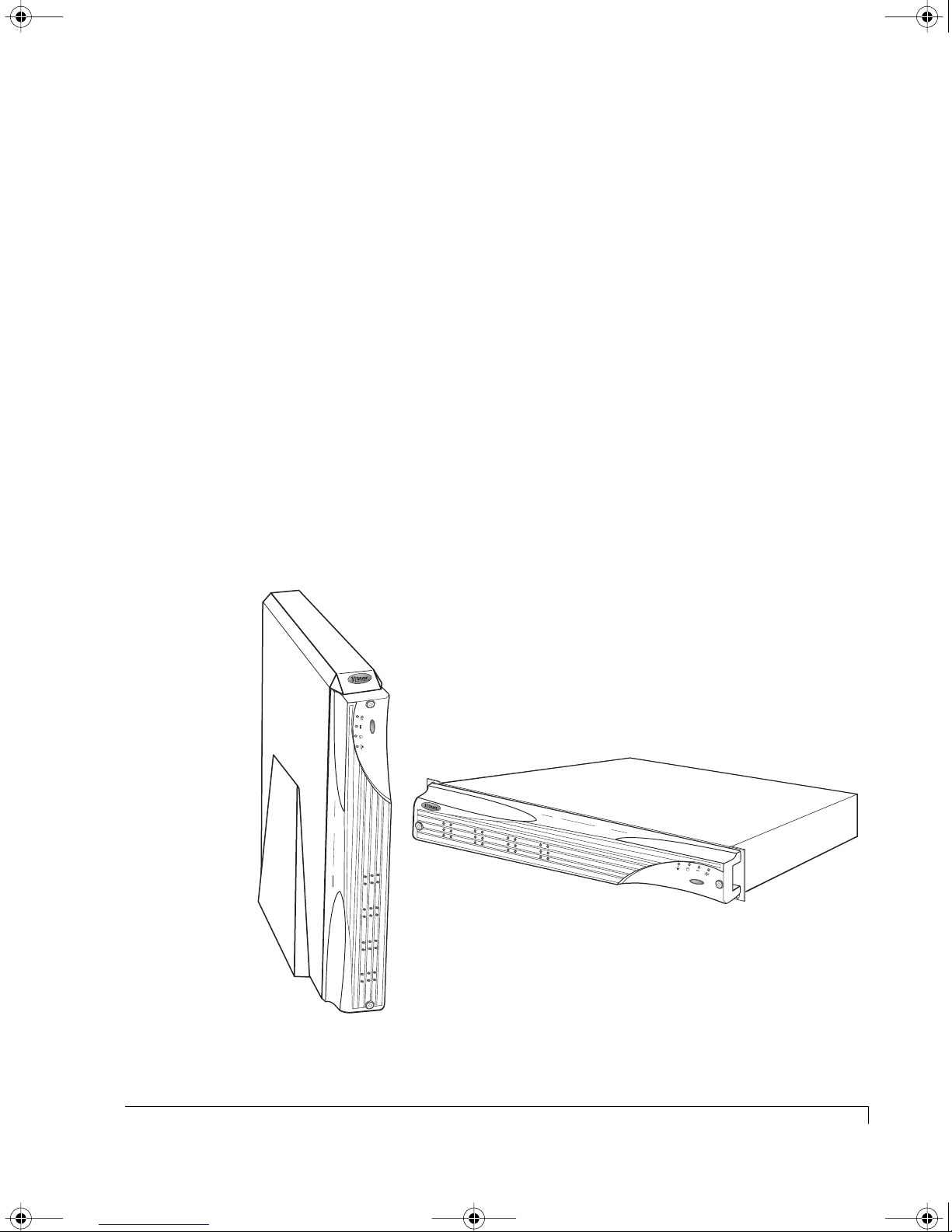
This chapter provides a description of the enclosure components and its onboard
monitoring systems.
The Components section identifies and gives a complete description of each
major component. The Monitoring section describes the enclosure’s LEDs, and
the manner in which the normal and abnormal conditions are presented.
M
R
A
L
A
T
E
S
E
R
R
E
S
E
T
A
L
A
R
M
Rack-Mount Model
Tower Model
NexStor 4100FS Series Storage System
1
Page 14
4100FS.book Page 2 Tuesday, July 8, 2003 4:35 PM
Chapter 1 - Getting Started
At a Glance
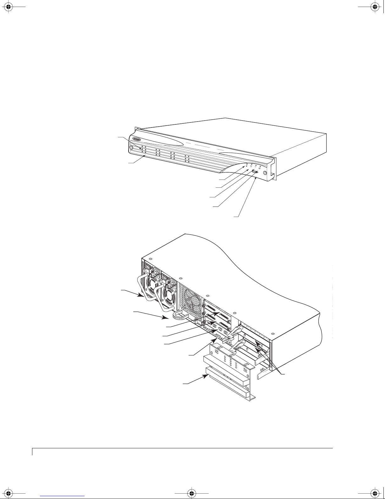
The following illustrations show the featured components of the NexStor 4100FS
Series Storage System. Familiarize yourself with its components prior to installing
and using the storage system.
Drive Status LEDs
(left column of LEDs)
Drive Activity LEDs
(right column of LEDs)
Power On LED
Channel Status LED
Power Supply Status LED
Fan Status LED
R
E
S
E
T
A
L
A
R
M
350-watt hot-pluggable
independent power supplies
Dual in-line 80-CFM hot
swappable cooling fans
SAFTE Disk I/O Card
Host SCSI I/O Card
Host I/O Card
SAF-TE Service & Controller
Service Ports
Controller
Cover Plate
Alarm Reset Button
C
h
a
n
n
e
l 1
C
C
h
a
h
nn
a
n
e
n
l 3
e
l 2
C
h
a
C
T
x
n
H
n
3
e
P
l 0
1
Rx
Tx
P
-
C
2
T
Rx
R
L
Tx
1
C
H
P
-
0
1
Rx
Tx
S
A
F
T
P
E
2
Rx
C
T
R
L
2
Controller 2
Controller 1
TERM PO
TO SUPPLY
ADD JUMPE
WER
J
P
1
J
P
3
J
TION
P
3
TION
R
TERM PO
TO SUPPLY
ADD JUMPE
WER
J
P
1
TERMINA
J
P
TO DISABLE
2
R
ADD JUMPE
J
P
4
R
TERMINA
J
P
TO
2
DISABLE
ADD JUMPE
J
P
4
R
Optional Dual
FC-to-Ultra160 SCSI
RAID Controllers
2
At a Glance
Component Views
Page 15

4100FS.book Page 3 Tuesday, July 8, 2003 4:35 PM
Components
This section provides a descriptive overview of each of the major components
that comprise the NexStor 4100FS Storage System enclosure.
Front Bezel
The front bezel houses the Status LEDs, Drive LEDs, and alarm reset button. When
removed, the user has access to the disk drives. The front bezel can be installed or
removed without interruption to system activities.
Embedded within the front bezel is the electronic package that provides the
communication with the SAF-TE processors (SEP). The SAF-TE processors control
the signals to the front panel through a smart interconnect. Power is applied to the
front bezel through a smart interconnect edge connector, where a control circuit
monitors the bezel for a proper connection. When the bezel is properly installed
and power is applied to the enclosure, the bezel is immediately energized.
Chapter 1 - Getting Started
Refer to “Control and Monitoring” on page 15 for details on the monitoring
functions.
Drive LEDs
R
e
s
e
t A
la
r
Status LEDs
Alarm Reset Button
m
Removable Front Bezel
To remove the bezel and gain access to the disk drives, use a Phillips screwdriver
to release both bezel fasteners, then grasp and remove the bezel. The fasteners
rotate one-quarter turn clockwise to lock and counter-clockwise to unlock.
Components
3
Page 16

4100FS.book Page 4 Tuesday, July 8, 2003 4:35 PM
Chapter 1 - Getting Started
AC Power
The power system consists of two 350-watt hot-pluggable power supplies, each
with independent AC power cords and cooling fans providing the enclosure with
“N+1” redundant power. Each power supply has auto-switching circuitry for use
with either 100V or 240V AC systems.
Power On LED
Fault LED
Power Supply
Power is applied to the enclosure by pressing each of the two power supply
On/Off switches to their “On” position. A Power On LED located on each power
supply will be illuminated indicating that AC power has been applied. The front
bezels’ Power On LED will also be illuminated indicating that power has been
applied.
Each power supply also incorporates an amber general Fault LED. If the power
supply is installed and power is not applied to the power supply or the power
supply cooling fan fails, the Fault LED will illuminate, along with an audible alarm.
The front bezels’ Power Supply Status LED will illuminate green when both
power supplies are on and operating normally. If only one power supply is
operational, the Power Supply Status LED will be illuminated amber.
Each power supply has an AC Power Cord Module. The module has a power
cord bale incorporated into the design to secure the power cord once it has been
properly inserted. The bale prevents inadvertent disconnects.
4
AC Power
Page 17
4100FS.book Page 5 Tuesday, July 8, 2003 4:35 PM
Cooling Fan Module
The cooling system consists of two high-performance (80-CFM) cooling fans
mounted in a single fan module which slides into a bay at the rear of the
enclosure. The design of the fan module provides for an easy-to-install user-
replaceable component in a live environment without interruption of service.
If any one fan should fail, cooling redundancy and efficiency are degraded. The
cooling fans and enclosure temperature are constantly monitored by the SES
processor for fault conditions. In the event of a fault condition the front panel Fan
Status LED will change from a green state to a solid amber state in the case of a fan
failure, or to a blinking amber green state in the case of an over-temperature
condition. In both cases an audible alarm sounds. The SES processor will also
provide notification data to monitoring software, such as StorView.
Chapter 1 - Getting Started
WARNING:
Do not operate the enclosure for extended periods of time (greater
than 5 minutes) with the cooling fan module removed.
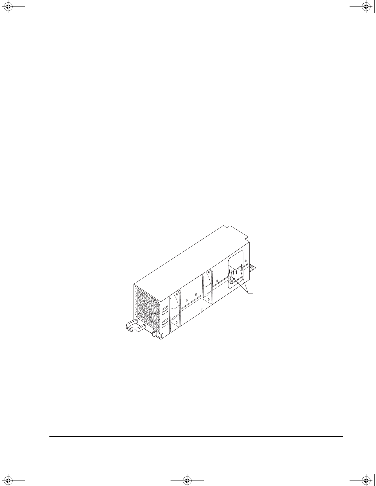
Fan Speed Override Control
Jumpers JP1 (Fan 0)
and JP2 (Fan 1)
Cooling Fan Module
The
NexStor 4100FS Storage System
monitors temperature in three different areas,
the drive bay, the RAID Controllers, and the power supplies. There are several
steps the storage system performs to prevent component damage due to over
temperature conditions.
Cooling Fan Module
5
Page 18

4100FS.book Page 6 Tuesday, July 8, 2003 4:35 PM
Chapter 1 - Getting Started
If the drive bay area reaches a temperature of 50°C (122°F) an audible alarm will
sound, the front panel Fan Status LED will toggle amber green, and the monitoring
software will post a warning message. These notifications give the user a warning
that some condition is causing the enclosure temperature to exceed the preset
value, and an action is required by the user to determine the cause and take
corrective measures. It may be due to a blockage of air flow or a low fan speed.
If any RAID Controller reaches a temperature of 65°C (149°F) an audible alarm will
sound, the front panel Fan Status LED will alternate amber and green, and the
monitoring software will post a warning message. If the temperature on any RAID
Controller continues to rise and reaches 71°C (159°F) the controller will flush its
cache and shutdown. If it is the only RAID Controller (Simplex mode) or the only
remaining controller (surviving controller from a failed over operation) then the
controller will also spin down the disk drives at this temperature.
If any power supply reaches 85°C (185°F) the power supply will shut down.
SAF-TE Disk I/O card
The
has a firmware-based VT-100 interface which provides
an option to manage fan speed. This option provides a whisper mode fan
operation for noise sensitive environments. When enabled (default), and based on
a set of conditions, the software will manage the cooling fans RPM speed to
maintain the enclosure temperature while minimizing noise levels. Refer to
“Enclosure Fan Speed Control” on page 100 for more details on using this option.
A manual override of the fan speed control is available for special circumstance
environments. Referring to the illustration on the preceding page, two jumpers are
provided on the fan module printed circuit board to override the software control
of the fan speeds. This hardware setting routes full power voltage to the fans for
maximum operational speed, which is greater than the maximum speed set by the
automatic software control. This configuration is normally used when fan speed
noises are not an issue, and the ambient operating temperature is at or above 30°C
(86°F), thus ensuring that maximum available cooling is being provided.
The jumpers JP1 and JP2 by default are offset, which enables the automatic fan
speed control. The jumper JP1 controls Fan 0 and JP2 controls Fan 1. Placing the
jumper on both pins for each jumper will override the automatic setting and
configure the fans to maximum power.
6
Cooling Fan Module
Page 19
4100FS.book Page 7 Tuesday, July 8, 2003 4:35 PM
SAF-TE Disk I/O Card
Chapter 1 - Getting Started
WARNING:
The SAF-TE Disk I/O card is NOT HOT SWAPPABLE. You must
POWER DOWN the enclosure prior to removing or installing this card.
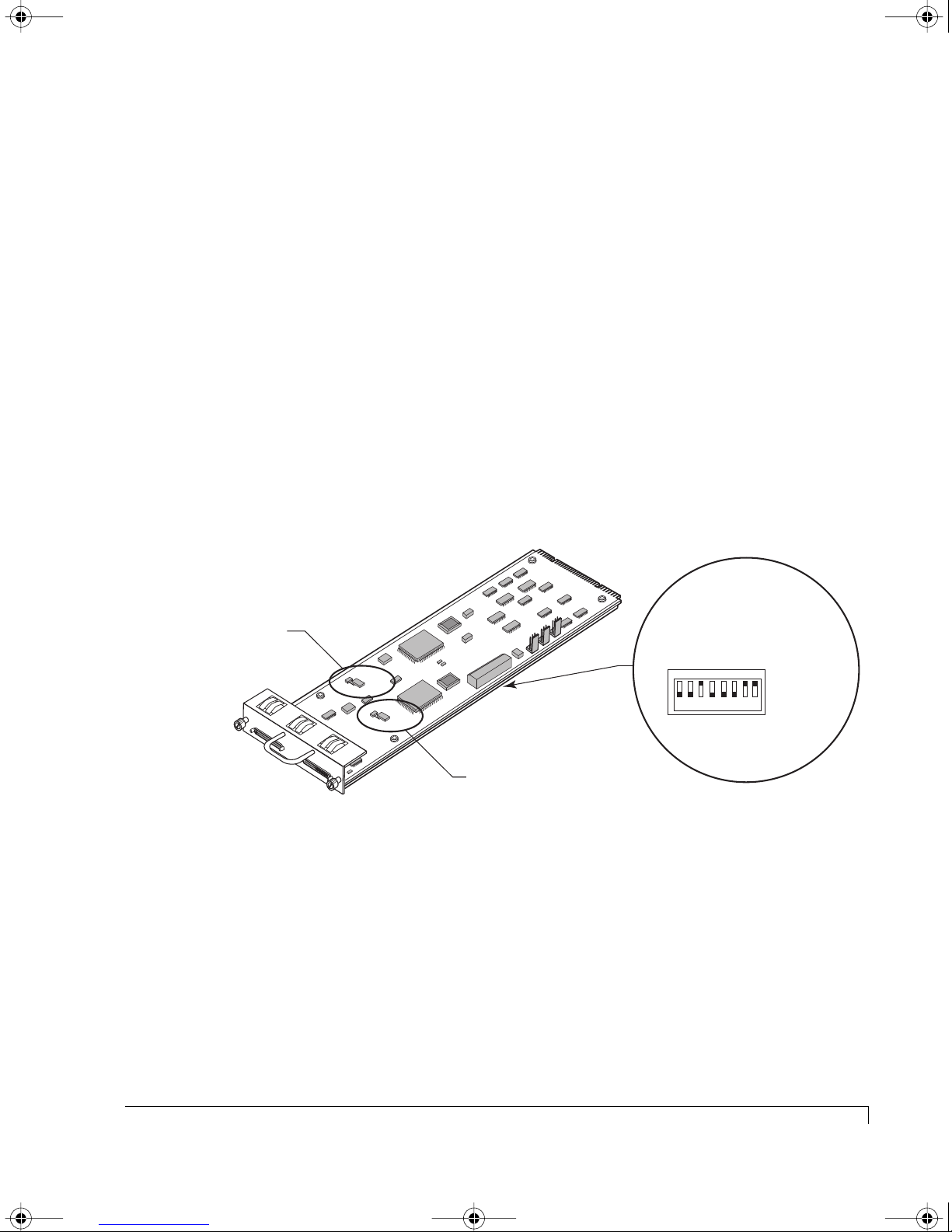
The SAF-TE Disk I/O card provides the built-in environmental and system status
monitoring, as well as, host connectivity to the disk drives, It also houses the
switches for setting SCSI IDs, VT-100 communication protocols, and drive spin up
options.
This card has two SAF-TE processors (SEPs) that continuously monitors the
enclosure for temperature status, fan status, power supply status, and SCSI
channel status. The SEPs are responsible for reporting environmentals and system
status to the front bezel LEDs/audible alarms and external monitoring software.
The monitoring system is fully compliant with SAF-TE specification protocol
version 1.0.
n1
n2
atio
Channel 1
Termination Jumper
Channel 1
C
hannel 2
atio
ur
ur
onfig
onfig
C
C
RAID
C
N
C
F
N
G
F
1
G
S
2
R
P
A
A
ID
S
R
B
CHANNEL -1
J
P
8
TERMINATION
TO
DISABLE
ADD JUMPER
J
P
7
TERMINATION
TO
DISABLE
ADD JUMPER
CHANNEL -2
P
E
A
A
1
U
R
D
D
E
LY
S
2
R
S
M
E
L
T
T
S
R
T
T
R
T
Spare
S
RDA
A
0
0
1
1234 5678
Channel 2
Termination Jumper
1
D
Spare 2
BAUD RateSelect
S1BDDLR
rive Start
e
mot
lay D
e
e
R
M
UP (Off -1)
DOWN (On -0)
rt
ive Sta
Dr
At power up, the SAF-TE processors read the SCSI switch settings and configures
the system for the appropriate addresses. It then executes instructions from
firmware performing a self-test diagnostics. The firmware is flash upgradeable
using the SAF-TE RS-232 Service port located below the I/O card slots at the rear
of the enclosure. The firmware also contains the necessary functions for
enclosure management via a VT-100 interface.
NOTE:
Specific switch settings are discussed later in the Installation chapter.
SAF-TE Disk I/O Card
SAF-TE Disk I/O Card
7
Page 20

4100FS.book Page 8 Tuesday, July 8, 2003 4:35 PM
Chapter 1 - Getting Started
The SAF-TE Disk I/O card has two 68-pin VHD/CI SCSI connectors which
provides the daisy-chain drive connectivity to the expansion JBOD enclosures.
The connectors are labeled “Channel 1” and “Channel 2.”
NOTE:
Termination is automatic and provided internally on the drive mid-plane
circuit board. It is configured using two sets of jumpers on the card.
Changes are not required for the RAID enclosure’s SAF-TE Disk I/O card jumpers.
These jumpers enable and disable the automatic termination. Add the jumper
(installed on both pins) to disable the automatic termination. JP8 for Channel 1
and JP7 for Channel 2. (The default position is the jumper is offset or
unjumpered, that is automatic termination is enabled.)
In daisy-chain configurations, you will be required to make changes to the
jumper settings in the enclosure’s SAF-TE Disk I/O card in that appears at the end
of the daisy-chain. In each supported configuration, a NexStor 4000S (JBOD)
enclosure will be the enclosure at the end of the daisy chain. In some
configurations multiple JBOD enclosures can appear at the end of the chain.
Those enclosures will need to have their jumper settings, JP7 and JP8, set to the
jumpered position. During installation setup, instructions are provided to
correctly configure the daisy-chain enclosure settings.
8
SAF-TE Disk I/O Card
Page 21
4100FS.book Page 9 Tuesday, July 8, 2003 4:35 PM
Host SCSI I/O Card
Chapter 1 - Getting Started
WARNING:
The Host
SCSI I/O
card is NOT HOT SWAPPABLE. You must POWER
DOWN the enclosure prior to removing or installing this card.
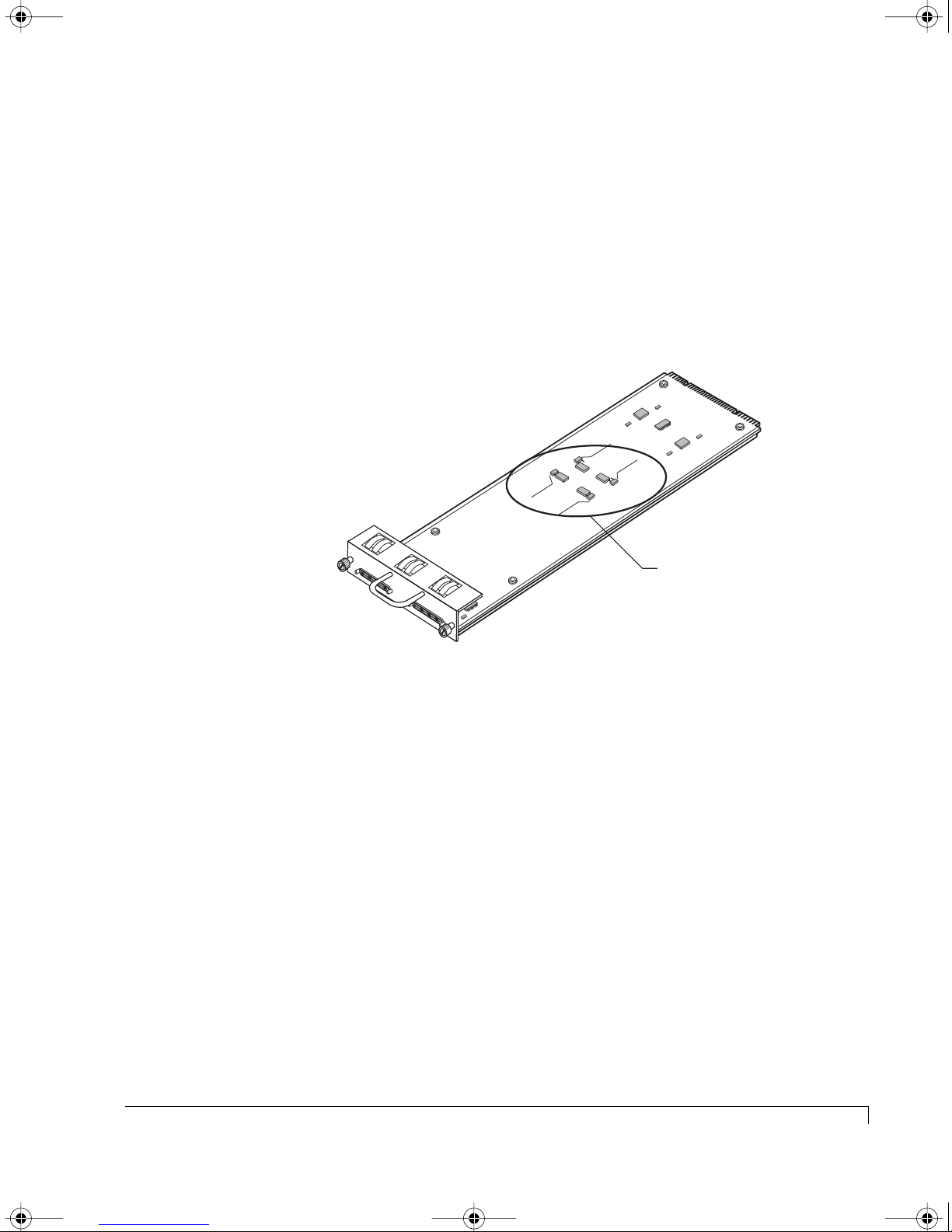
The Host SCSI I/O card is installed to provide the Channel 0 and Channel 3 SCSI
drive ports. These two drive channels are used for drive channel expansion
providing the connection to the NexStor 4000S JBOD enclosure(s).
NOTE:
The SAF-TE Disk I/O card provides Channels 1 and 2 SCSI drive ports.
TERMINATION
JP4
TO DISABLE
ADD JUMPER
JP2
Termination Jumpers
for Disk Channels 0 and 3
Channel 3
Channel 0
JP3
C
hannel -0
JP1
TERM POWER
TO SUPPLY
ADD JUMPER
C
hannel -3
Host SCSI I/O Card
The Host SCSI I/O cards are configured with automatic termination and do not
require any external terminators. Jumpers on the card are provided to configure
Term Power and Termination, however their settings do not require any changes
for the RAID enclosure. The default settings are: JP1 and JP2 unjumpered or
offset, and JP3 and JP4 installed on both pins.
Host SCSI I/O Card
9
Page 22
4100FS.book Page 10 Tuesday, July 8, 2003 4:35 PM
Chapter 1 - Getting Started
Fibre Channel Host I/O Card
WARNING:
The
Fibre Channel Host I/O
card is NOT HOT SWAPPABLE. You must
POWER DOWN the enclosure prior to removing or installing this card.
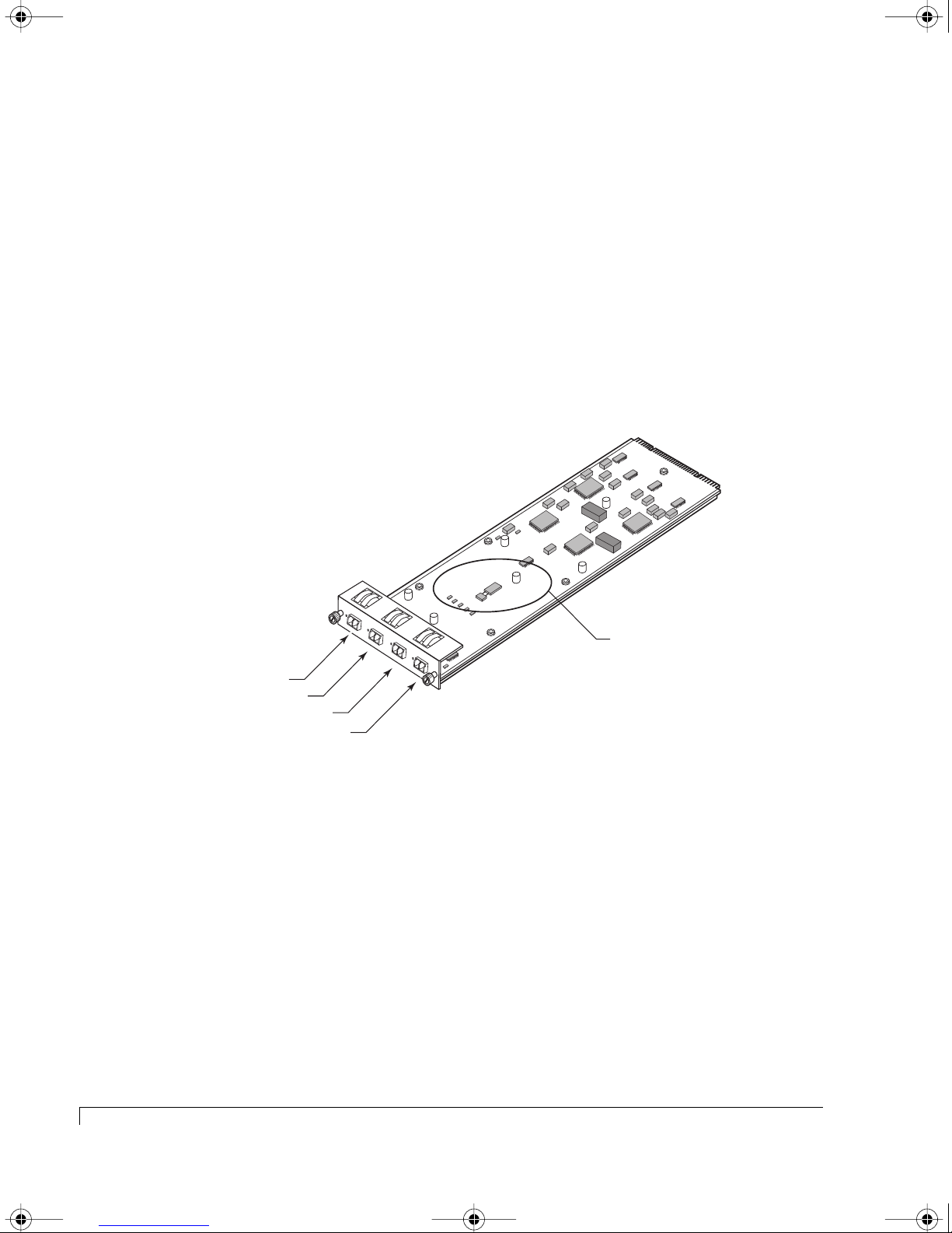
The Fibre Channel Host I/O card provides the four host ports configured with
internal active hubs and Small Form Factor Pluggable (SFP) module cages for
connectivity from the host computer (server) to each RAID controller. The cards
support both optical and copper SFP transceivers providing NCITS T11 Fibre
Channel compliant device connectivity at speeds of 1.0625 Gb per second or
2.125 Gb per second.
OFF = 2 GIG
O
N = 1 G
JUM
PER
IG
JP
5
T
P1
P2
P4
P3
x
P1
R
x
T
x
P
2
R
x
T
x
P4
R
x
T
x
P3
Jumper sets FC Loop Speed.
(On configures 1 Gb mode and
offset sets the 2 Gb mode.)
The card has a jumper installed to allow the user to set the Fibre Channel Loop
speed. With the jumper, (JP5), installed it c0onfigures the loop speed to 1 Gb and
with the jumper off set it configures the loop speed to 2 Gb mode.
In the Installation chapter you will find individual cabling diagrams for each
supported topology that assist with the host to enclosure cabling. To ensure
proper failover and failback operations and LUN presentation, cable your system
based on the diagram for your selected topology.
10
Fibre Channel Host I/O Card
Fibre Channel Host I/O Card
Page 23
4100FS.book Page 11 Tuesday, July 8, 2003 4:35 PM
RAID Controllers
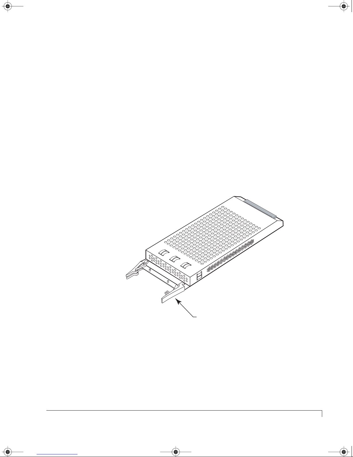
The enclosure houses one or two RAID Controllers. It supports configurations for
single controller Stand-Alone topologies and dual controller Active-Active/
Active-Passive topologies.
Chapter 1 - Getting Started
The RAID Controller is a Fibre Channel
-to-
Ultra160
SCS
I RAID controller. It has
four 2 Gb Fibre Channel host ports and four Ultra160 SCSI disk channel ports.
This controller is occasionally referred to throughout this manual and in the
software as a JFS224 model.
The
controller
operates in one of three different modes: Stand-Alone, Active-Active.
or Active-Passive. In the Stand-Alone mode, the controller operates autonomously.
In the Active-Active/Active-Passive mode, the two controllers operate as a pair. If
one controller fails in the Active-Active/Active-Passive mode, the other can take
over the failed controller’s work.
The Disk Array Administrator software is embedded in the controller firmware,
and requires no specific software drivers for the host operating system. These
utilities are accessed through the Java-based AdminiStor storage management
software or a VT-100 terminal. (See either the AdminiStor Software Guide or the
VT-100 Software Guide.)
Ejector Handles
RAID Controller
RAID Controllers
11
Page 24
4100FS.book Page 12 Tuesday, July 8, 2003 4:35 PM
Chapter 1 - Getting Started
Optical SFP Transceiver
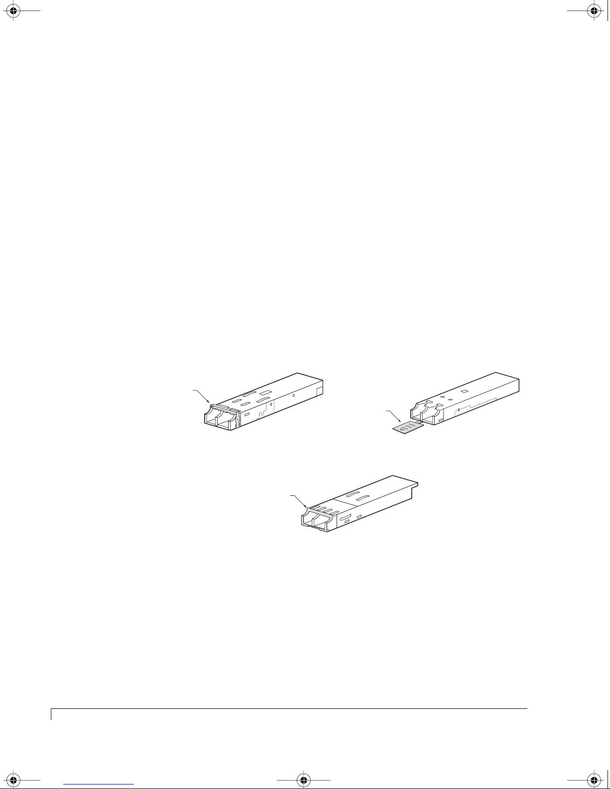
The Fibre Channel Host I/O card uses a hot-swappable Small Form-Factor
Pluggable (SFP) transceiver. The optical transceiver provides operations up to 2.5
Gb per second. The transceiver includes a lost signal detect circuit which provides
TTL logic high output when an unusable input signal is detected.
The transceivers are available in a few different models which are determined by
the type of ejector mechanism.
The type A model uses a pivoting mechanism. Use the edge of your finger tip
or the finger nail to engage the ejector and pull towards you.
The type B model uses a similar mechanism to the type A except it rotates
about a pivot point. Use the edge of your finger tip or the finger nail to
engage the ejector and pull towards you.
The type C model uses a pull tab to eject the transceiver. Grasp and pull the
tab to release the transceiver.
Ejector Release Lever
Ejector Release Tab
Type A
Ejector Release Lever
Type C
SFP Optical Transceiver Models
Type B
The SFP transceiver is Class 1 Laser safety compliant and conforms to Class 1 eye
safety standards.
CAUTION:
Do not look into the laser light beam for any extended period of time.
Dust covers are provided to protect the
recommend using the dust covers provided when a connector is not in place.
12
Optical SFP Transceiver
optical
transceivers’ optics. We highly
Page 25

4100FS.book Page 13 Tuesday, July 8, 2003 4:35 PM
Channel 1
Channel 3
CH 3
T
x
P
-1
R
Chapter 1 - Getting Started
T
E
R
M
T
O
P
S
O
A
U
W
D
P
E
D
J
P
R
L
P
J
Y
U
1
M
P
E
J
P
3
R
M
I
N
J
A
T
P
I
O
3
N
B
L
E
R
M
IN
A
T
IO
N
B
L
E
Channel 2
Channel 0
x
T
x
P
-2
R
x
T
x
CH 0
P
-1
R
x
T
x
P
-2
R
x
C
o
n
tro
lle
r 2
C
o
n
tro
lle
r 1
R
T
E
R
M
T
O
P
S
O
A
U
W
D
P
E
D
J
P
R
L
P
J
Y
U
1
T
E
D
I
S
A
M
P
E
R
T
E
D
I
S
A
M
P
E
R
M
J
P
P
E
T
2
R
O
A
D
D
J
J
U
P
4
J
P
T
2
O
A
D
D
J
J
U
P
4
Install the Dust Covers
when the optical transceiver
port is not in use.
Installing and Removing SFP Dust Covers
Optical SFP Transceiver
13
Page 26
4100FS.book Page 14 Tuesday, July 8, 2003 4:35 PM
Chapter 1 - Getting Started
RS-232 Service Ports
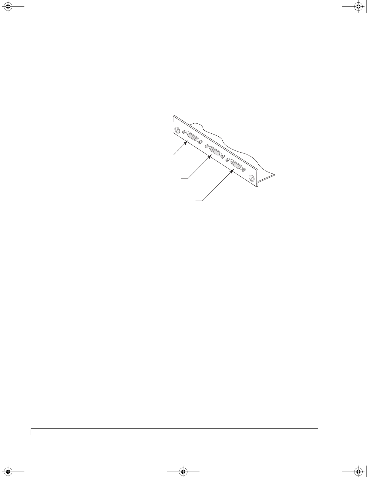
Located below the I/O card slots is the SAF-TE service port and two RAID
Controller service ports. Refer to the illustration under “At a Glance” for the port
locations on the rear panel.
Controller 1: Service Port
SAF-TE Service Port
CTRL 1
SAF-TE
CTRL 2
Controller 2: Service Port
SAF-TE Service and RAID Controller Service Ports
The SAF-TE Service port provides an RS-232 serial interface to the SAF-TE Disk
I/O card allowing firmware uploads, and maintenance/service monitoring of the
SEPs. This port is labeled “SAF-TE.”
The two RAID Controller service ports, which are labeled “CTRL 1” and “CTRL 2,”
provide an interface to each RAID Controller. They provide access to the
firmware-based Disk Array Administration software and provide options to
update the firmware. The ports are standard DB9 connectors which provides a
connection using a null-modem serial cable for VT-100 terminal and host serial
port communication via emulation software.
14
RS-232 Service Ports
Page 27
4100FS.book Page 15 Tuesday, July 8, 2003 4:35 PM
Control and Monitoring
An integral part of the NexStor 4100FS Series enclosures is its control and monitor
capabilities.
The
SAF-TE processors
conditions such as enclosure temperature, cooling fans, power supplies, and
bus status
audible alarm notifications. This monitored information is also communicated to
external monitoring software.
Refer to “VT-100 Interface Enclosure Monitoring” on page 110 for complete
details.
The RAID Controllers provide monitoring data for its environmental condition
and logical arrays. They communicate that data to the front bezel LEDs,
third-party configuration and monitoring software, and the VT-100 Disk Array
Administration firmware-based software interface for management and
monitoring. (Refer to the software user’s guide for configuration, management,
and monitoring of the controllers and logical arrays.)
Chapter 1 - Getting Started
provide monitoring data for the enclosure environmental
SCSI
. This data is reported to the monitoring system to provide LED and
Drive Status LEDs
(left column of LEDs)
Drive Activity LEDs
(right column of LEDs)
Power On LED
Channel Status LED
Power Supply Status LED
Fan Status LED
Alarm Reset Button
Reset Alarm
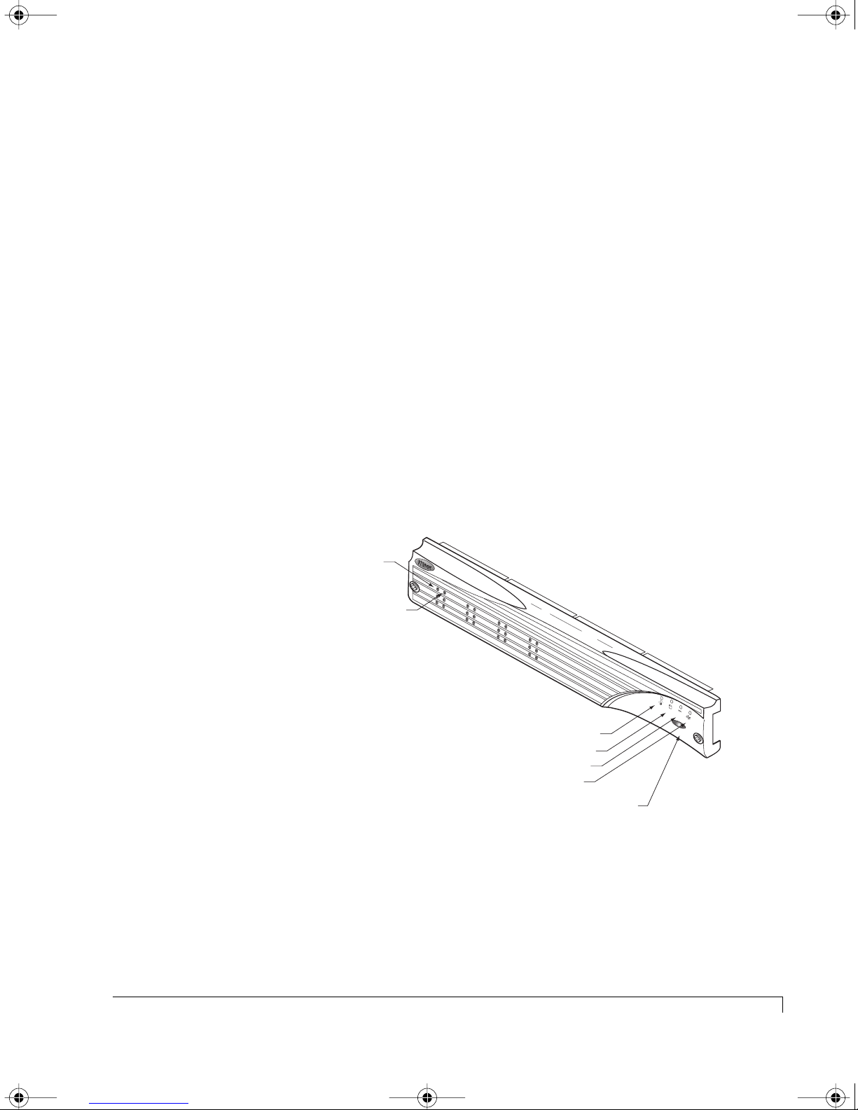
Front Bezel LEDs and Reset Button Identification
The NexStor 4100FS Series incorporates a “One-Touch Annunciation” which
provides an LED readout of the current switch configuration, host interface type,
bus configuration, communication BAUD setting, drive spin-up settings, and
controller status. Refer to “One-Touch Annunciation” on page 85 for more details.
Control and Monitoring
15
Page 28

4100FS.book Page 16 Tuesday, July 8, 2003 4:35 PM
Chapter 1 - Getting Started
Status Indicator LEDs
The Status Indicator LEDs comprise the Power-On LED, Channel Status LED,
Power Supply Status LED, and Fan Status LED. These series of LEDs are grouped
on the right side of the front bezel directly above the Alarm Reset button. The
following is an description of each of these LEDs.
Power-On LED
The Power-On LED signifies that the enclosure is powered on and will be
illuminated green when power has been applied.
Channel Status LED
The Channel Status LED will indicate the status of the logical arrays.
Power Supply Status
The Power Supply Status LED indicates the condition of the power supplies. The
LED will illuminate steady green when both power supplies are functioning
normally and will change to amber if one power supply should fail or is turned off.
Fan Status
The Fan Status LED indicates the condition of the cooling fans. The LED will
illuminate green when both fans are functioning normally and will change to
amber if any of the fans fail.
Drive LEDs
The Drive LEDs are located on the left side of the front bezel in between the
ventilation ribs and comprise the Drive Status LEDs and Drive Activity LEDs. The
Drive LEDs are grouped in pairs and are in the general location of the disk drive
slot. There are 12 Drive Status and Drive Activity LEDs, one group o pair for each
disk drive.
Refer to “Drive LEDs” on page 91 for detailed information.
16
Status Indicator LEDs
Page 29

4100FS.book Page 17 Tuesday, July 8, 2003 4:35 PM
Audible Alarm
An audible alarm will sound when any of the enclosure’s component condition
changes to an abnormal state. To silence the alarm, press the Alarm Reset button
located on the front bezel. The corresponding alarms’ LED will remain
illuminated until the condition returns to a normal state.
Chapter 1 - Getting Started
Audible Alarm
17
Page 30

4100FS.book Page 18 Tuesday, July 8, 2003 4:35 PM
Chapter 1 - Getting Started
18
Audible Alarm
Page 31

4100FS.book Page 19 Tuesday, July 8, 2003 4:35 PM
Chapter 2
Theory of Controller Operation
This chapter provides a functional overview and understanding of the supported
topologies and operating modes for the NexStor 4100FS Series Storage System.
With this information, you will be able to make the best choice based on the
supported topologies, to set up your storage solution.
There are three operating modes available for the NexStor 4100FS Series: StandAlone, Active-Active, and Active-Passive. The NexStor 4110FS model with its single
RAID controller supports the Stand-Alone operating mode, and the NexStor
4120FS with its dual RAID controllers supports the active-active or active-passive
operating modes. Either mode can function in single or dual port configurations.
Operating Modes Overview
The operating modes let you configure the RAID controllers to support a variety
of host environments.
■ Stand-Alone Dual Port – Use this mode when you have a NexStor 4110FS
and require single-HBA host access.
■ Active-Active Single Port – Use this mode when you have a NexStor 4120FS
and require both controllers to be active and processing host I/O
operations. This operating mode uses one of the FC host ports of each
RAID controller and supports single or dual host system connections.
19
Page 32

4100FS.book Page 20 Tuesday, July 8, 2003 4:35 PM
Chapter 2 - Theory of Controller Operation
■ Active-Active Dual Port – Use this mode when you have a NexStor 4120FS
and require both controllers to be active and processing host I/O
operations. This operating mode uses one both FC host ports of each RAID
Controller and supports single or dual host system connections.
■ Active-Passive Dual Port – Use this mode when you have a NexStor 4120FS
and require only one RAID controller to be active. The other controller is
in a passive mode as a “hot” standby. This operating mode does not
provide the performance compared to either of the Active-Active modes.
The naming conventions are broken down into two parts: the first part refers to
the number of controllers and their state, and the second part refers to the state
of the controller’s host ports (not to be confused with the physical I/O ports).
Stand-Alone designates a single controller system, and Active-Active or
Active-Passive designates a dual controller system.
The Single Port or Dual Port component of the name convention refers to the
number of enabled Host ports on the active controller. Note that there are two
host ports on each controller (internally).
Operating Mode Number of
Stand-Alone Dual Port
(NexStor 4110FS)
Active-Active Single Port
(NexStor 4120FS)
Active-Active Dual Port
(NexStor 4120FS)
Active-Passive Dual Port
(NexStor 4120FS)
Controllers
12 4
21 4
22 4
2 2 (active controllers only) 4
Number of Active Host Ports per
Controller
Number of Disk
Channels
Another consideration when selecting one of these topologies is whether you will
enable or disable the internal hubs. Each NexStor 4100FS Series Storage System
enclosure has built-in internal hubs. These internal hubs, when enabled,
essentially replace the need for external hub hardware. They provide for up to
four (4) host connections. You can enable or disable this feature using the
AdminiStor software or the VT-100 interface.
20
Operating Modes Overview
Page 33
4100FS.book Page 21 Tuesday, July 8, 2003 4:35 PM
Stand-Alone Mode
In Stand-Alone mode, the RAID Controller operates autonomously. The controller
has two Fibre Channel (FC) Host ports, which are labeled in the diagrams as “FC1”
and “FC2.” This operating mode uses both FC host ports.
Advantages:
■ Low cost entry-level RAID storage solution that is field upgradeable.
■ Allows the use of dual host ports to maximize bandwidth and host IOPs.
(For example: this configuration is ideal for sequential access patterns,
where disks can supply more than 160 MB/sec of data to a host.)
■ Host system has multiple paths to each array (with host driver).
■ All arrays appear on both host ports at the same LUN positions in Dual Port
mode. (If both ports are connected to the same host, the host will see a
given array twice unless it does special processing to detect duplicate paths
to array. A host device driver may provide this functionality.)
■ Hosts can detect redundant paths to an array by matching array serial
numbers from SCSI inquiry data.
Chapter 2 - Theory of Controller Operation
Disadvantages:
■ The controller is a single point of failure.
■ Third-party software is required for upstream path fail-over.
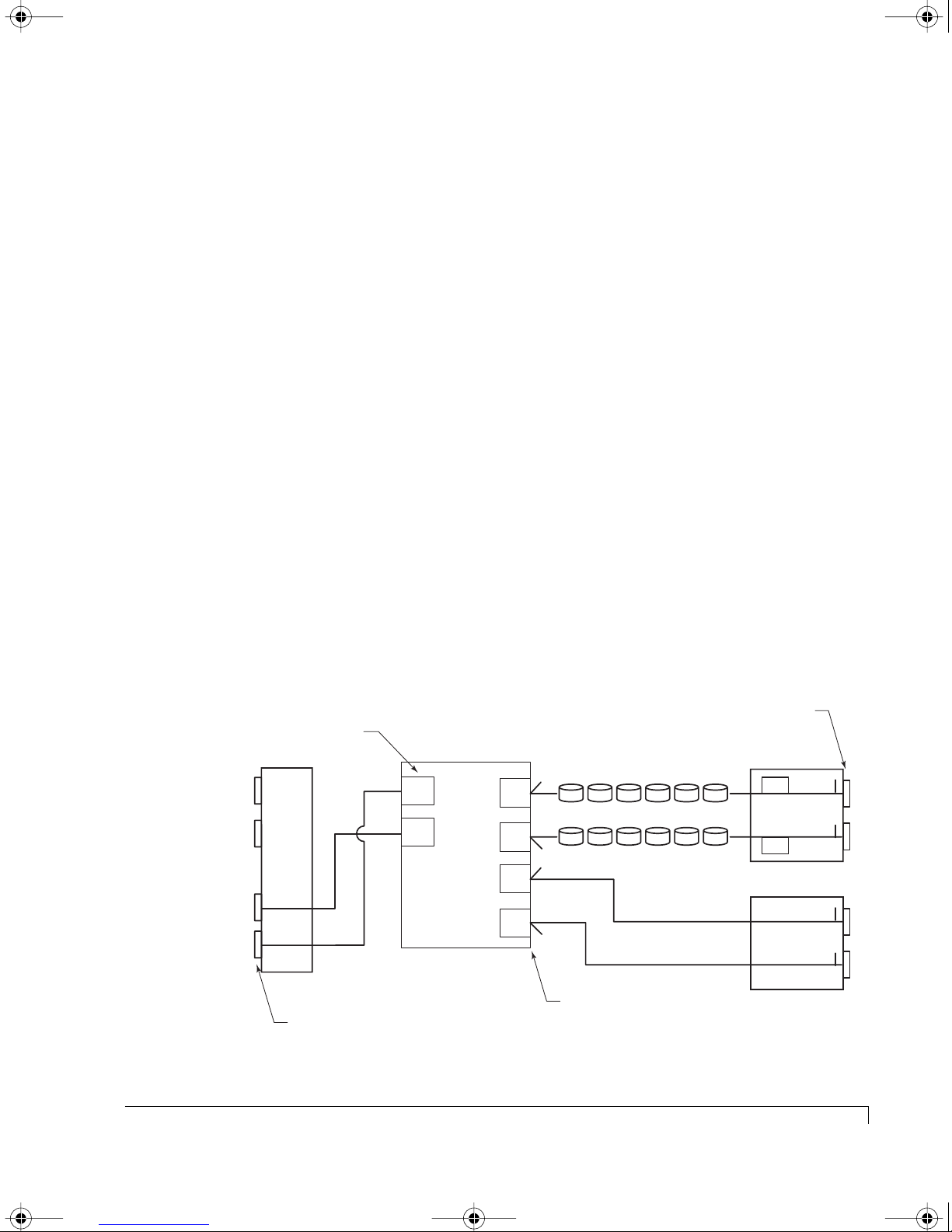
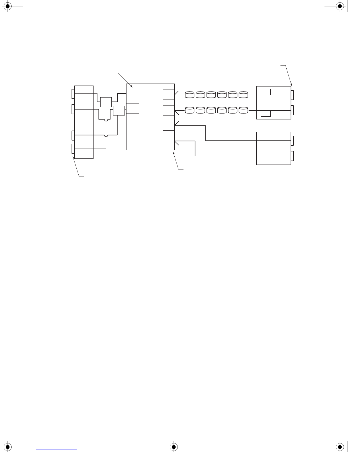
The following two diagrams depicts the logical function of this operating mode.
Drive I/O Connectors
Controller FC Host Ports
HOST I/O
P1
P2
P4
P3
T= Location of internal termination
Host I/O Connectors
RAID Controller
FC1
Active
Active
FC2
Controller 1 (A)
Disk
CH1
Disk
CH2
Disk
CH0
Disk
CH3
T
T
T
T
Controller Disk Ports
Drives 7 - 12
Drives 1 - 6
SEP
SEP
SAF-TE Disk I/O
Host SCSI I/O
T
CH 1 CH 2
T
T
CH 0 CH 3
T
Stand-Alone Dual Port with Hubs Disabled
Stand-Alone Mode
21
Page 34
4100FS.book Page 22 Tuesday, July 8, 2003 4:35 PM
Chapter 2 - Theory of Controller Operation
Controller FC Host Ports
HOST I/O
P1
HUB
P2
P4
P3
RAID Controller
FC1
Active
Active
FC2
HUB
Controller 1 (A)
T= Location of internal termination
Disk
CH1
Disk
CH2
Disk
CH0
Disk
CH3
Drive I/O Connectors
T
T
T
T
Drives 7 - 12
Drives 1 - 6
SEP
SEP
SAF-TE Disk I/O
T
CH 1 CH 2
T
T
CH 0 CH 3
T
Controller Disk Ports
Host I/O Connectors
Host SCSI I/O
Stand-Alone Dual Port with Hubs Enabled
Active-Active Mode
In the Active-Active mode, the two RAID Controllers cooperate to provide
redundancy. If one controller fails, the remaining controller will take over the
failed controller’s functionality. Each controller has two Fibre Channel Host ports,
they are labeled in the diagrams as FC1 and FC2.
In the Active-Active:Single Port mode, one FC Host port is normally active, and
the other is normally passive. In a failed over condition, the passive port of the
surviving controller becomes active and assumes the identity of the failed
controller. This failover process occurs without user intervention.
In the Active-Active:Dual Port mode, both FC Host ports are active and each
controller normally presents the LUNs it owns on both of its FC Host ports. This
provides the host with dual-ported access. However, when a controller fails, the
surviving controller presents its LUNs on one of its FC Host ports and the LUNs of
the failed controller on its other FC Host port.
22
Active-Active Mode
Page 35

4100FS.book Page 23 Tuesday, July 8, 2003 4:35 PM
Presentation of LUNs in Active-Active:Single Port Mode
Chapter 2 - Theory of Controller Operation
Controller Status Controller 1
FC 1 Host Port
Both controllers online Controller 1
LUNs
Controller 1 Fails Inactive Inactive Controller 2
Controller 2 Fails Controller 1
LUNs
Controller 1
FC 2 Host Port
Passive Controller 2
Controller 2
LUNs
Controller 2
FC 1 Host Port
LUNs
LUNs
Inactive Inactive
Controller 2
FC 2 Host Port
Passive
Controller 1
LUNs
Presentation of LUNs in Active-Active:Dual Port Mode
Controller Status Controller 1
FC 1 Host Port
Both controllers online Controller 1
LUNs
Controller 1 Fails Inactive Inactive Controller 2
Controller 2 Fails Controller 1
LUNs
Controller 1
FC 2 Host Port
Controller 1
LUNs
Controller 2
LUNs
Controller 2
FC 1 Host Port
Controller 2
LUNs
LUNs
Inactive Inactive
Controller 2
FC 2 Host Port
Controller 2
LUNs
Controller 1
LUNs
In either mode, arrays can only be accessed by the controller that currently owns
them. One controller will have no visibility to the others’ arrays. If one controller
fails, the surviving controller will take ownership of all arrays. Pool spares and
unassigned disks are visible to both controllers.
The two controllers communicate via the back-end disk buses. Although many
different message types are sent between the two controllers, the majority of the
data is write cache data. In the default write-back caching mode, any data that the
host writes to one controller is copied to the other controller before a good status
is returned to the host. By mirroring the data, if a controller fails, the surviving
controller will have a copy of all data that has not been written to the disk.
NOTE: The controllers communicate with each other using SCSI initiator IDs 6
and 7 on each of the disk channels. You should not change these IDs.
Each controller will send heartbeat messages to its partner controller. If a
controller does not receive a heartbeat message within a set time period, it will
kill the other controller assuming that it has malfunctioned. After killing the other
controller, it will take ownership of the arrays and will activate its passive host
port to assume the defunct controller’s identity.
Active-Active Mode
23
Page 36

4100FS.book Page 24 Tuesday, July 8, 2003 4:35 PM
Chapter 2 - Theory of Controller Operation
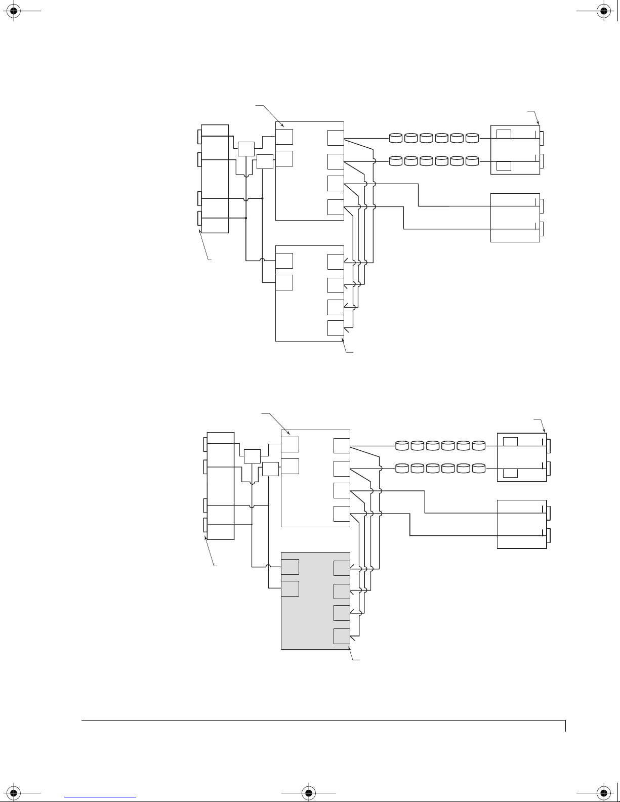
The following diagrams illustrate the logical function of the controllers when both
are active and then again when one controller has failed. First we present the
controllers in Single Port mode, then in Dual Port mode.
Controller FC Host Ports
HOST I/O
P1
P2
P4
P3
Host I/O
Connectors
HUB
HUB
FC1
FC2
Controller 1 (A)
FC2
FC1
Controller 2 (B)
RAID Controller
Active
Passive
RAID Controller
Active
Passive
Disk
CH1
Disk
CH2
Disk
CH0
Disk
CH3
Disk
CH1
Disk
CH2
Disk
CH0
Disk
CH3
Drives 7 - 12
Drives 1 - 6
T
T
T
T= Location of internal termination
T
Controller Disk Ports
Drive I/O Connectors
Active-Active Single Port Mode with Hubs Enabled and Both Controllers Active
Controller FC Host Ports
HOST I/O
P1
P2
P4
P3
Host I/O
Connectors
HUB
HUB
RAID Controller
FC1
Active
Active
FC2
Controller 1 (A)
ACTIVE (FAILED OVER)
RAID Controller
Inactive
FC2
Disk
CH1
Disk
CH2
Disk
CH0
Disk
CH3
Disk
CH1
Drives 7 - 12
Drives 1 - 6
T
SEP
SEP
SAF-TE Disk I/O
Drive I/O Connectors
T
T
T
T
Host SCSI I/O
SEP
SEP
SAF-TE Disk I/O
Host SCSI I/O
CH 1 CH 2
CH 0 CH 3
T
CH 1 CH 2
T
T
CH 0 CH 3
T
Active-Active Single Port Mode with Hubs Enabled and Controller 2 Failed
24
Active-Active Mode
FC1
Controller 2 (B)
Inactive
FAILED
Disk
CH2
Disk
CH0
Disk
CH3
T
T
T= Location of internal termination
T
Controller Disk Ports
Page 37
4100FS.book Page 25 Tuesday, July 8, 2003 4:35 PM
Chapter 2 - Theory of Controller Operation
Controller FC Host Ports
FC1
FC2
Controller 1 (A)
FC2
FC1
Controller 2 (B)
RAID Controller
Active
Active
ACTIVE
RAID Controller
Active
Active
ACTIVE
Disk
CH1
Disk
CH2
Disk
CH0
Disk
CH3
Disk
CH1
Disk
CH2
Disk
CH0
Disk
CH3
Drives 7 - 12
Drives 1 - 6
T
T
T
T= Location of internal termination
T
Controller Disk Ports
HOST I/O
P1
HUB
P2
P4
P3
Host I/O
Connectors
HUB
Active-Active Dual Port Mode with Hubs Enabled and Both Controllers Active
Drive I/O Connectors
SEP
SEP
SAF-TE Disk I/O
Host SCSI I/O
T
CH 1 CH 2
T
T
CH 0 CH 3
T
Controller FC Host Ports
HOST I/O
P1
P2
P4
P3
RAID Controller
Drives 7 - 12
Drives 1 - 6
HUB
HUB
FC1
FC2
Controller 1 (A)
Active
(CTRL 1)
Active
(CTRL 2)
Disk
CH1
Disk
CH2
Disk
CH0
Disk
CH3
ACTIVE (FAILED OVER)
RAID Controller
Host I/O
Connectors
FC2
FC1
Controller 2 (B)
Inactive
Inactive
FAILED
Disk
CH1
Disk
CH2
Disk
CH0
Disk
CH3
T
T
T
T= Location of internal termination
T
Controller Disk Ports
Active-Active Dual Port with Hubs Enabled and Controller 2 Failed
Drive I/O Connectors
SEP
SEP
SAF-TE Disk I/O
Host SCSI I/O
T
CH 1 CH 2
T
T
CH 0 CH 3
T
Active-Active Mode
25
Page 38

4100FS.book Page 26 Tuesday, July 8, 2003 4:35 PM
Chapter 2 - Theory of Controller Operation
In the failed-over condition, the active controller will present its native identity on
one FC Host port, and the failed-over controller’s identity on the other port. This
is slightly different when using a dual port configuration, where each array is
presented on both FC Host ports.
After the controller has failed-over, the user can replace the failed controller with
a new controller, and the arrays will fail-back to the new controller without
intervention. If you want to retry the failed controller, it’s necessary to release the
kill line that the survivor asserts. This is accomplished using AdminiStor software
or VT-100 Disk Array Administrator software (Other Controller Menu – Unkill
Other option).
If you replace a failed controller with a new controller, the new controller will
attempt to retrieve its configuration (see “Understanding Mirrored Operations” on
page 29) from the surviving controller. This means that the replacement
controller will boot up with the same configuration as the controller it replaced.
If the surviving controller for some reason does not contain a valid mirrored
configuration, you must manually configure the replacement controller. The correct
host target ID must be set, and the Active-Active operating mode must be enabled.
The Active-Active controller system makes some assumptions about the host
operating system’s SCSI processing. The host must retry incomplete commands
after a specific time period. This retry is necessary because a host may issue a
command to a controller, the controller fails over, and the new controller does
not have a copy of the command.
Advantages:
■ LUN isolation with the single port-single host system.
■ Dedicated LUNs with a single port-dual host system.
■ Access to all LUNs with a dual port-dual host quad cabling configuration.
■ Provides transparent fail-over and fail-back.
■ No single point of failure with the Active-Active-Dual Port configuration,
must have third party clustering and file share/file lock software installed.
Disadvantages:
■ Host HBA or the Fibre loop are single points of failure.
■ In single host configuration, the host system is also a single point of failure.
■ No upstream fail-over with a single host that has dual HBAs or dual host
systems.
■ Protected LUN sharing between two host systems is not supported without
the use of third party file share/file lock software.
26
Active-Active Mode
Page 39

4100FS.book Page 27 Tuesday, July 8, 2003 4:35 PM
Active-Passive Mode
In the Active-Passive mode, there is one active and one passive RAID Controller.
The primary (active) controller operates with both of its FC Host ports enabled and
presents all LUNs on both ports to maximize bandwidth. The secondary (passive)
controller keeps both its FC Host ports passive, and does not service any LUNs. Both
controllers monitor each other’s heartbeats and the passive controller receives write
data and parity logs from the active controller.
If the active controller fails, normal fail-over occurs to the passive controller, which
becomes active by enabling both of its FC Host ports
arrays
.
Controller 1 is the default active controller. Controller 2 is always passive unless
Controller 1 fails. The default active controller is not selectable.
Chapter 2 - Theory of Controller Operation
and takes ownership of all
Because the active controller does not have to mirror the passive controllers data,
more write-back cache memory can be made available to the active controller. This
means that half the cache memory can be dedicated to writes and half to reads. This
is the same allocation used in Stand-Alone mode.
Each controller sends heartbeat messages via the SCSI buses to its partner
controller. If a controller does not receive a heartbeat message within a set time
period, it will kill the other controller assuming that it has malfunctioned. After
killing the other controller, it will take ownership of the arrays and will activate
its passive host port to assume the defunct controller’s identity.
NOTE: The controllers communicate with each other using SCSI initiator IDs 6
and 7 on each of the disk channels. You should not change these IDs.
On the following page, you will find diagrams which illustrates the Active-Passive
mode logical functions when the controllers are operating in a normal condition and
then in a failed condition.
Advantages:
■ Transparent failover and failback.
■ Single point of failure is the host system. (There are no single points of
failure when dual host systems are configured with clustering software.)
■ Upstream fail-over.
Disadvantages:
■ Lower performance than the Active-Active mode.
■ Upstream fail-over requires third party software.
Active-Passive Mode
27
Page 40

4100FS.book Page 28 Tuesday, July 8, 2003 4:35 PM
Chapter 2 - Theory of Controller Operation
■ Careful administration is necessary, since all the arrays are reported twice
to the host operating system which requires the use of third party file
share/file lock software to prevent data overwrites.
HOST I/O
P1
P2
P4
P3
P1
P2
P4
P3
Controller FC Host Ports
HUB
HUB
FC1
FC2
Controller 1 (A)
RAID Controller
Active
Active
Disk
CH1
Disk
CH2
Disk
CH0
Disk
CH3
Drives 7 - 12
Drives 1 - 6
ACTIVE
RAID Controller
Host I/O
Connectors
FC2
FC1
Controller 2 (B)
Passive
Passive
PASSIVE
Disk
CH1
Disk
CH2
Disk
CH0
Disk
CH3
T
T
T
T= Location of internal termination
T
Controller Disk Ports
Active-Passive Dual Port with Hubs Enabled and Controller 1 Active
Controller FC Host Ports
HOST I/O
Host I/O
Connectors
HUB
HUB
RAID Controller
FC1
Inactive
Inactive
FC2
Controller 1 (A)
FAILED
RAID Controller
Active
FC2
FC1
Active
Controller 2 (B)
ACTIVE (FAILED OVER)
Disk
CH1
Disk
CH2
Disk
CH0
Disk
CH3
Disk
CH1
Disk
CH2
Disk
CH0
Disk
CH3
Drives 7 - 12
Drives 1 - 6
T
T
T
T= Location of internal termination
T
Controller Disk Ports
Drive I/O Connectors
SEP
SEP
SAF-TE Disk I/O
Host SCSI I/O
Drive I/O Connectors
SEP
SEP
SAF-TE Disk I/O
Host SCSI I/O
T
CH 1 CH 2
T
T
CH 0 CH 3
T
T
CH 1 CH 2
T
T
CH 0 CH 3
T
Active-Passive Dual Port with Hubs Enabled and Controller 1 Failed
28
Active-Passive Mode
Page 41

4100FS.book Page 29 Tuesday, July 8, 2003 4:35 PM
Understanding Mirrored Operations
The mirroring feature causes configuration changes to be mirrored to the
opposite controller in an Active-Active configuration. The mirrored configuration
is stored in the other controller’s firmware (Flash). If a controller fails and is
replaced, then on boot up, it attempts to retrieve this configuration data from the
opposite controller. The intent is that the user will not need to reconfigure a new
controller when it is replaced.
NOTE: Dual RAID controller operations require that both controllers must have
If a replacement controller uses its mirrored configuration, you will see it print a
message during boot (saying it’s using the mirrored configuration), and then it
will reboot (rebooting is necessary for the mirrored configuration to take effect).
Chapter 2 - Theory of Controller Operation
the same version firmware installed.
Here’s how the mirrored configuration works in different scenarios:
■ Stand-Alone mode – The feature is not active.
■ Active-Active mode where both controllers are operating normally – Each
controller uses its own local configuration.
■ Active-Active mode where one controller boots and the other controller
does not boot due to some problem – The controller that boots uses its
local configuration.
■ Active-Active mode where one controller is up when a new replacement
controller boots – the new controller attempts to get its mirrored
configuration from the other controller. If it is not available, it will try to
use its local configuration. If that is not available, then it will use the
default settings.
NOTE: When Clear Configuration is selected in the Flash Utility menu, both the
local Flash configuration and the other controller’s mirrored configuration
image are cleared. Also, there is an option (J) in the Flash Utility menu
that can be used to tell a booting controller to temporarily ignore the
mirrored configuration. This can be used, if for whatever reason, the
mirrored configuration should not be used by a booting controller. This is
primarily a safeguard, because a retrieved mirrored configuration is
checked extensively before it is used.
Understanding Mirrored Operations
29
Page 42

4100FS.book Page 30 Tuesday, July 8, 2003 4:35 PM
Chapter 2 - Theory of Controller Operation
A Word about Clustering
Minimizing Downtime for Maximum Data Availability
So-called open systems, such as Windows NT servers, just don’t provide the level
of availability that IS managers are familiar with on mainframes. A partial solution
to this problem is server clustering.
Clusters consist of two or more loosely coupled systems with a shared-disk
subsystem and software that handles failover in the case of a node (host) failure.
In most cases, hardware/software failover is performed automatically and is
transparent to users, although users will experience performance degradation as
processing is shifted to another cluster node. In some cases this failover can
occur in a matter of seconds.
High availability of data and applications is by far the most compelling reason to
go with clustering technology. For example, the accepted rule is that stand-alone
UNIX systems can provide 99.5% uptime. Adding a RAID subsystem can increase
the uptime to 99.9%. The goal of clustering is 99.99% availability.
Beyond clustering, fault-tolerant systems can provide 99.9999% uptime. At the
high end, continuous-processing systems offer virtually 100% uptime.
Although the increase from 99.5% to 99.99% availability may seem insignificantly
small, it adds up in terms of minutes per year of downtime. For example,
assuming a 7x24 operation, 99.5% uptime translates into 2,628 minutes — or
more than 43 hours of downtime per year. In contrast, 99.99% uptime translates
into less than one hour (52 minutes) of downtime per year.
Availability figures relate primarily to unplanned downtime. But the advantages
of clusters in terms of planned or scheduled downtime are even more significant.
If you figure two to sixteen hours per month for a server in a large shop.
Planned downtime requires shutting down stand-alone systems entirely. Result:
100% loss of processing for the duration of the downtime. But, with cluster, you
can shut down one node and off-load the processing to other nodes in the cluster
with no interruption of processing.
30
A Word about Clustering
Page 43

4100FS.book Page 31 Tuesday, July 8, 2003 4:35 PM
High availability is not the only benefit of clustering. In some cases, users may
see advantages in the areas of performance, scalability, and manageability. In
reality, you can expect a 1.6x (80% efficiency) to 1.8x (90% efficiency)
performance increase as you go from one node to two nodes. Going from one
node to a four node cluster generally yields a 2.5x or 3x performance boost.
However, the cluster performance is application dependent. For example, READ
operations may yield a 1.8x performance increase going from one to two nodes,
but in a WRITE intensive application, you may only see a 1.4-1.6x improvement.
Although clusters seem to be relatively simple, they involve complex technology
that can be implemented in a variety of ways. The number of nodes supported
and type of interconnection used, and a number of other features differentiate
cluster implementations. One area of implementation is the manner in which
distributed lock manager is implemented. Some perform this at the user level and
others in the kernel, with the latter enhancing performance.
Chapter 2 - Theory of Controller Operation
In addition to the differing features you should consider the following:
Does the cluster:
• have the ability to hot load new nodes without bringing down the
whole cluster?
• provide automatic or manual failover?
• load balance?
• use a journalized file system?
• provide a fast cluster failover?
• allow for the nodes to be geographically located?
Minimizing Downtime for Maximum Data Availability
31
Page 44

4100FS.book Page 32 Tuesday, July 8, 2003 4:35 PM
Chapter 2 - Theory of Controller Operation
How Available are Clusters?
The following tables outlines the maximum availability per downtime in the
different architectures:
Architecture Maximum Availability Downtime per Failure Downtime per Year
(in minutes)
Continuous
Processing
Fault-Tolerant 99.9999% Cycles 0.5 - 5
Clusters 99.9 - 99.999% Seconds to
High Availability 99.9% Minutes 500 - 10,000 (disk
Stand Alone
System
100.00% None 0
5 - 500
minutes
mirroring)
99.5% Hours 2,600 - 10, 000
(without disk
mirroring)
Application of Availability
The NexStor 4100FS Series Storage System implementation of availability within
its supported topologies are as follows:
Architecture Corresponding Topology
Continuous Processing Not Available
Fault-Tolerant Active-Passive:Dual Port
Cluster Active-Active:Dual Port
High Availability Active-Active:Single Port
Stand Alone System Stand-Alone:Dual Port
32
How Available are Clusters?
Page 45

4100FS.book Page 33 Tuesday, July 8, 2003 4:35 PM
Chapter 3
Setup and Installation
Overview
This chapter describes the procedures to install and setup the NexStor 4100FS
Series Storage System. Each section will step you through the hardware
installation, cabling and topology configurations, and upgrades.
It is important to thoroughly review this information and perform the steps of
procedures in each applicable section, in the order in which they are presented.
This will ensure a smooth and trouble-free installation.
The installation is divided into three sections. The first section describes installing
the enclosure(s) into the rack cabinet.
The second
SAF-TE Disk I/O card switch settings and the enclosure-to-enclosure cabling. The
SAF-TE card switches settings determine the SCSI IDs, RAID Addressing, and disk
spinup options. These configurations are categorized by the number of disk
drives. For example, a NexStor 4110FS/4120FS with two daisy-chained NexStor
4000S JBOD enclosures will be described as the “RAID - 36 Drive Configuration.”
The third section, “Topology Host Cabling,” describes the cabling of the primary
section is
“Enclosure Configuration” which describes setting the
RAID storage enclosure to the host system(s).
operating modes: Stand-Alone Dual Port, Active-Active Single Port, Active-Active
Dual Port, or Active-Passive Dual Port.
The topologies are based on the
33
Page 46

4100FS.book Page 34 Tuesday, July 8, 2003 4:35 PM
Chapter 3 - Setup and Installation
Storage System Detailed Installation
This first section describes preparing and installing the NexStor 4100FS Series
Storage System enclosure(s) into the rack cabinet or the enclosure into its tower
stand (“Installing the Storage System into the Tower Stand” on page 37).
After installing the hardware components, go to the Enclosure Configuration
section and set the SAF-TE Disk I/O card switches and enclosure cabling for your
drive configuration. Then locate the operating mode you wish to employ in the
Topology Host Cabling section and perform the steps to complete the host
cabling.
Installing the Storage System Enclosure into the Rack Cabinet
1 Install the storage enclosure(s) into the rack cabinet.
Select an appropriate location within your rack cabinet. You should consider
the location of the enclosure(s) in relationship to each other to ensure that
the cables will easily reach between enclosures.
CAUTION: The power supplies should be removed prior to installing the
enclosure into the rack cabinet. The enclosure chassis could be
damaged during installation due to the added weight of the power
supplies.
NOTE: Ensure that the selected location in the rack cabinet has adequate air
flow for the front to side and side to side areas.
2 Remove each enclosure from its shipping carton and inspect for obvious
damage. Place the enclosure on a flat surface to work from.
3 Remove the front bezel from the accessory box and store it in a location
where it will not be damaged. It will be installed later in the installation
procedures.
4 Remove the power supplies.
From the rear of the enclosure, remove each power supply by grasping its
handle and pressing in on the release latch with your thumb as you pull each
power supply from the enclosure. Repeat for the other power supply.
34
Storage System Detailed Installation
Page 47
4100FS.book Page 35 Tuesday, July 8, 2003 4:35 PM
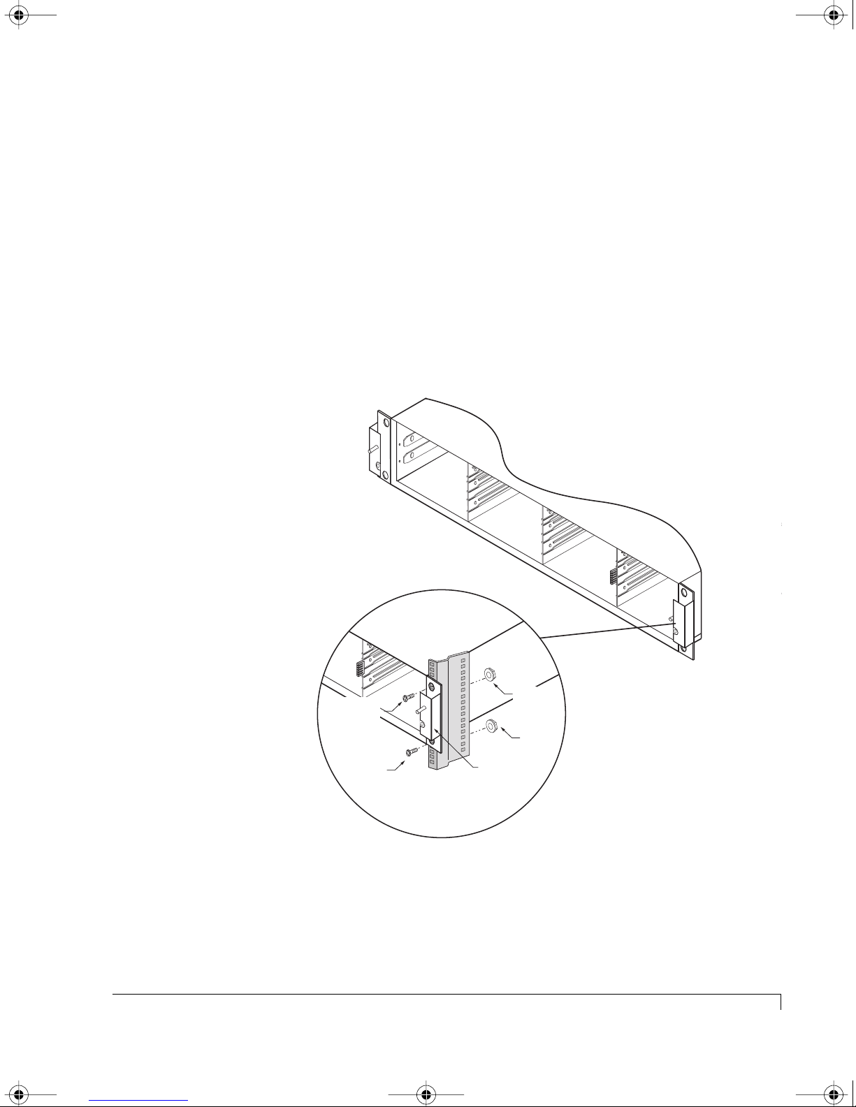
5 Locate the mounting hardware in the accessory kit (mounting rails, screws,
and nuts – on some rack installations you will use cage nuts and on some
racks they will be standard nuts).
Chapter 3 - Setup and Installation
NOTE:
It will be helpful to have an assistant available during the installation.
6 Lift and secure the enclosure into the rack cabinet.
a Position the enclosure in the cabinet at the desired location.
b Secure the left and right front chassis ears to the rack cabinet’s front
vertical members using the supplied screws and nuts. Ensure that they
are even horizontally.
Front Rack Vertical
Member
Mounting
Screw
Mounting
Screw
Nut
Nut
Chassis Ear
Attaching the Chassis Ears
c Install the rear mounting rails using the supplied screws and nuts.
From the rear of the rack cabinet, slide one of the mounting rails into the
slot provided on the left side of the enclosure.
Installing the Storage System Enclosure into the Rack Cabinet
35
Page 48
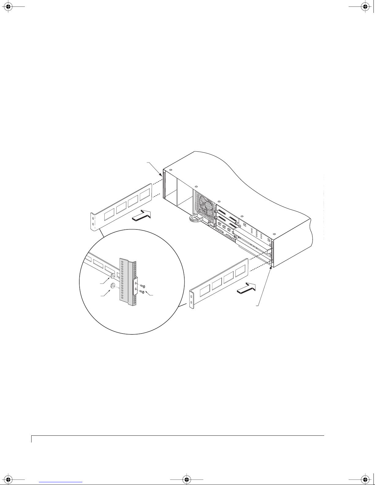
4100FS.book Page 36 Tuesday, July 8, 2003 4:35 PM
Chapter 3 - Setup and Installation
Push the rail in the slot until it fits the depth of the rack cabinet drawing
the enclosure level and tight. It should mate with the rear rack cabinet
vertical member.
NOTE:
Be sure that the enclosure is level. Do this by verifying that the
same height mounting location slots on both the front and rear
rack cabinet vertical member being used.
d Secure the left side rail to the vertical member using the screws and nuts.
e Repeat the substeps 6(c) and 6(d) for the right side rail.
Rail Slot
T
E
R
M
T
O
P
S
O
A
U
W
D
P
E
D
JP1
P
R
L
J
Y
U
M
P
E
R
JP3
T
E
R
M
T
O
P
S
O
A
U
W
D
P
E
D
JP1
P
R
L
J
Y
U
M
T
JP2
E
P
R
E
M
T
R
O
I
N
D
JP3
A
A
T
IS
D
I
O
A
D
N
B
J
JP4
L
U
E
M
P
E
R
T
JP2
E
R
M
T
O
I
N
D
A
A
T
I
S
D
IO
A
D
N
B
J
JP4
L
U
E
M
P
E
R
C
o
n
tro
lle
r
2
C
o
n
tro
lle
r 1
Rear Rack Vertical Member
C
h
a
n
n
e
l
1
C
C
h
a
h
n
a
n
n
e
n
l
e
0
l
2
C
h
a
T
n
x
n
e
l
P
3
-1
R
x
T
x
P
-2
C
T
R
R
x
L
T
1
x
P
-1
R
x
S
A
T
F
x
T
E
P
-2
R
x
C
T
R
L
2
36
Nut
Nut
Mounting
Screws
7 Re-install the power supplies. Do this by aligning the power supply with its
open bay and slide the power supply in.
The power supply will fit flush and the latch will reset as the power supply
reaches its fully seated position.
8 Continue now with “Completing the Installation” on page 40.
Installing the Storage System Enclosure into the Rack Cabinet
Rail Slot
Attaching the Rails
Page 49

4100FS.book Page 37 Tuesday, July 8, 2003 4:35 PM
Installing the Storage System into the Tower Stand
1 Remove the enclosure from its shipping carton and inspect for obvious
damage. Place it on a flat surface to work from.
2 Remove the front bezel from the accessory box and store it in a location
where it will not be damaged. It will be installed later in the installation
procedures.
3 Remove the power supplies.
From the rear of the enclosure, remove each power supply by grasping its
handle and pressing in on the release latch with your thumb as you pull each
power supply from the enclosure. Repeat for the other power supply.
4 Remove the cooling fan module.
Chapter 3 - Setup and Installation
Place your finger in the fan module handle and press with your thumb to
release the latch while pulling the module from the enclosure.
5 Remove the two rear mounting rails. Grasp and pull each rail from the
chassis.
NOTE: The mounting rails were installed in the slots at the factory for the
purpose of shipping.
6 Remove the tower stand case from its shipping carton and inspect for
obvious damage.
7 Locate the accessory kit in the tower shipping carton. It should contain eight
10-32 pan head screws and conversion instructions. (Note, the instructions
enclosed in the box are applicable to upgrading an existing installation.)
8 Rotate the enclosure chassis so that the power supply bays are on the top.
9 Carefully slide the enclosure chassis into the tower stand until it fits flush as
indicated in the illustration (A) on the following page.
10 Secure the top and bottom chassis ears to the tower stand using two each
10-32 pan head screws as indicated in the illustration (B) on the following
page.
11 Re-install the rear mounting rails into the slots at the rear of the chassis as
indicated in the illustration (C) on the following page.
Installing the Storage System into the Tower Stand
37
Page 50
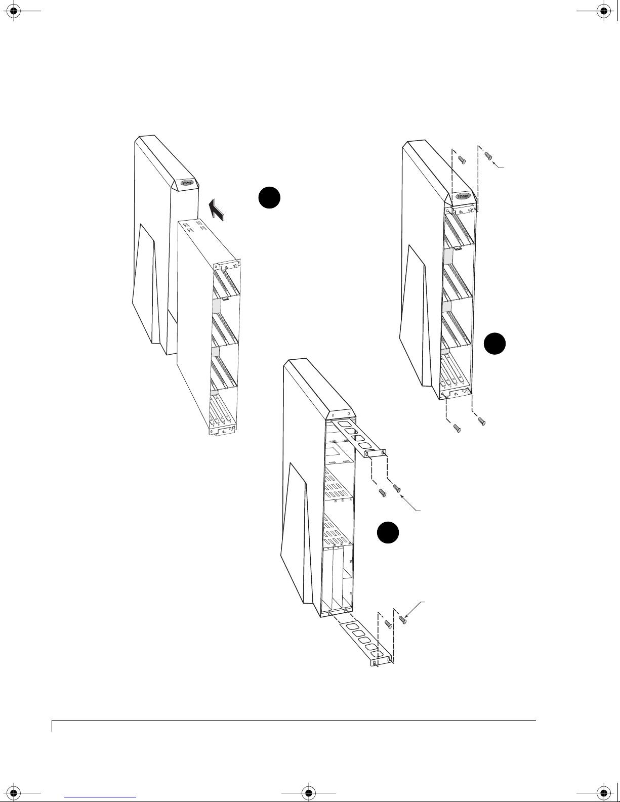
4100FS.book Page 38 Tuesday, July 8, 2003 4:35 PM
Chapter 3 - Setup and Installation
12 Using the remaining two sets (4) of 10-32 pan head screws, secure the top
and bottom slide rails as indicated in the illustration (C) below.
Mounting
Screw
A
C
Mounting
Screws
Mounting
Screws
B
38
Installing the Storage System into the Tower Stand
Inserting and Securing the Chassis
Page 51

4100FS.book Page 39 Tuesday, July 8, 2003 4:35 PM
13 Re-install the cooling fan module. Slide it into its open bay and ensure the
release latch resets indicating the fan module has completely seated.
14 Re-install the power supplies. Slide each power supply into its open bay and
ensure the release latch resets indicating the power supply has completely
seated.
15 Continue now with “Completing the Installation” on page 40.
Chapter 3 - Setup and Installation
Installing the Storage System into the Tower Stand
39
Page 52
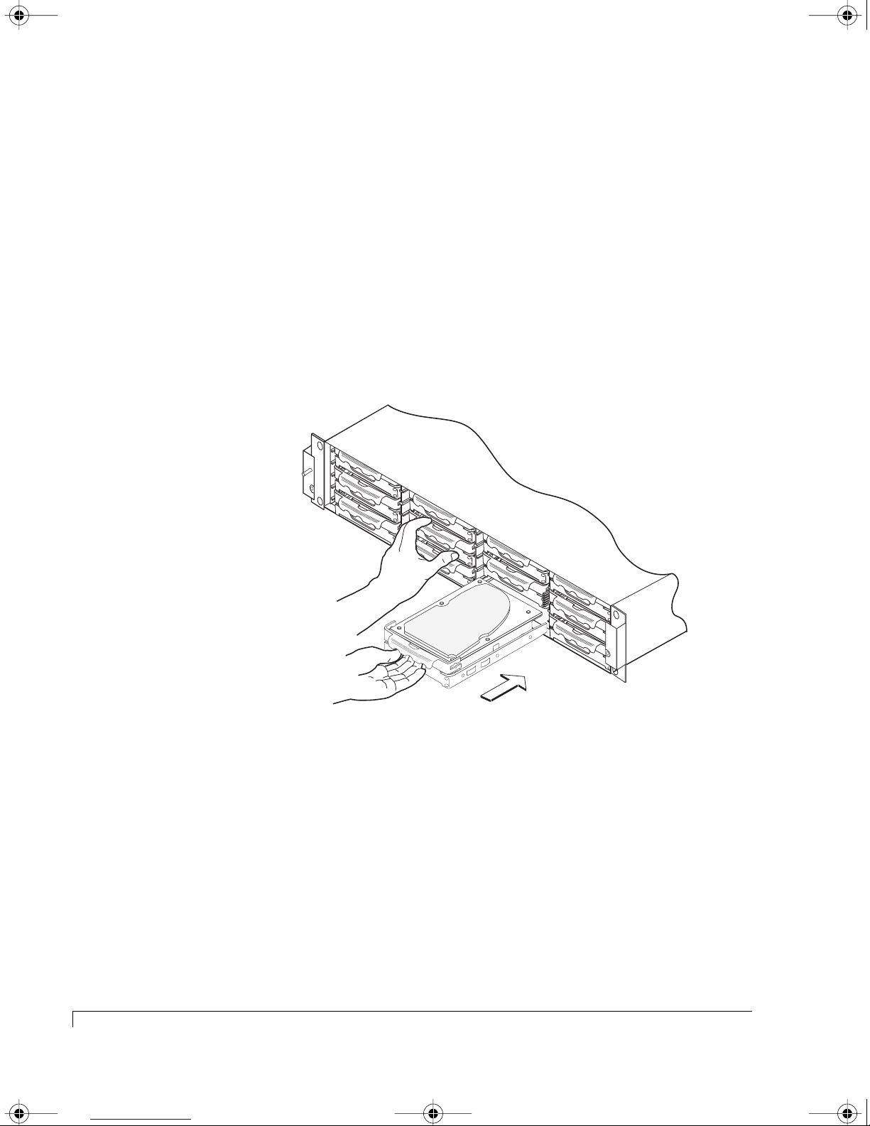
4100FS.book Page 40 Tuesday, July 8, 2003 4:35 PM
Chapter 3 - Setup and Installation
Completing the Installation
1 Install the disk drives.
a Remove each drive from its shipping container and remove the anti-static
protective packaging. Inspect each drive for obvious damage.
b From the front of the storage enclosure, install each disk drive into its
drive slot.
Align the carrier rails with the rail grooves in the drive bay. The drive
carrier tension clips ensure that the disk drive fits very tight, so it requires
some force to push the drive into its bay. Ensure that the drive seats
completely. Repeat this step to populate all the drive slots.
c Re-install the front bezel. Ensure that the bezel mounts to the two stud
post and the bezel lip fits under the chassis top.
Secure the front bezel. Using a Phillips screwdriver, rotate the fasteners
clockwise one-quarter turn to secure the bezel locks.
2 Install the power cords and secure them using the power cord bales.
CAUTION: Ensure that the power supply On/Off switches are in their OFF
position.
40
Completing the Installation
Installing Disk Drives
Page 53
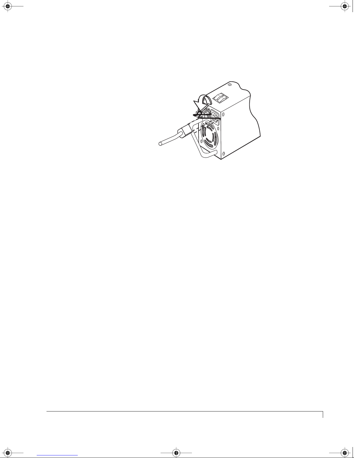
4100FS.book Page 41 Tuesday, July 8, 2003 4:35 PM
a Ensure that the orientation is such that when the power cord is inserted,
Chapter 3 - Setup and Installation
the bale will be the top of the cord and will fit over and onto the cord.
Bale fits over and onto
the power cord.
Attaching the Power Cord Bales
b Connect the other end of the power cords into a three-hole grounded
outlets or UPS power system.
c Repeat steps 2(a) and 2(b) for the other power cord.
3 Repeat the above steps for each additional storage system enclosure you will
be installing.
This completes the physical hardware installation.
Before You Continue...
The next section, Enclosure Configuration, includes steps and diagrams for
setting the SAF-TE Disk I/O card switches and attaching the required SCSI data
cables for each drive configuration. Locate the applicable configuration and refer
to the steps and diagrams to set the card switches and cable your system.
The Topology Host Cabling section includes steps and diagrams for cabling the
primary RAID storage enclosure to the host computer(s). Review the procedure
steps, then locate the applicable topology and cable your system based on the
diagrams.
The last section of this chapter provides the steps to properly power on or power
off your storage system.
Completing the Installation
41
Page 54
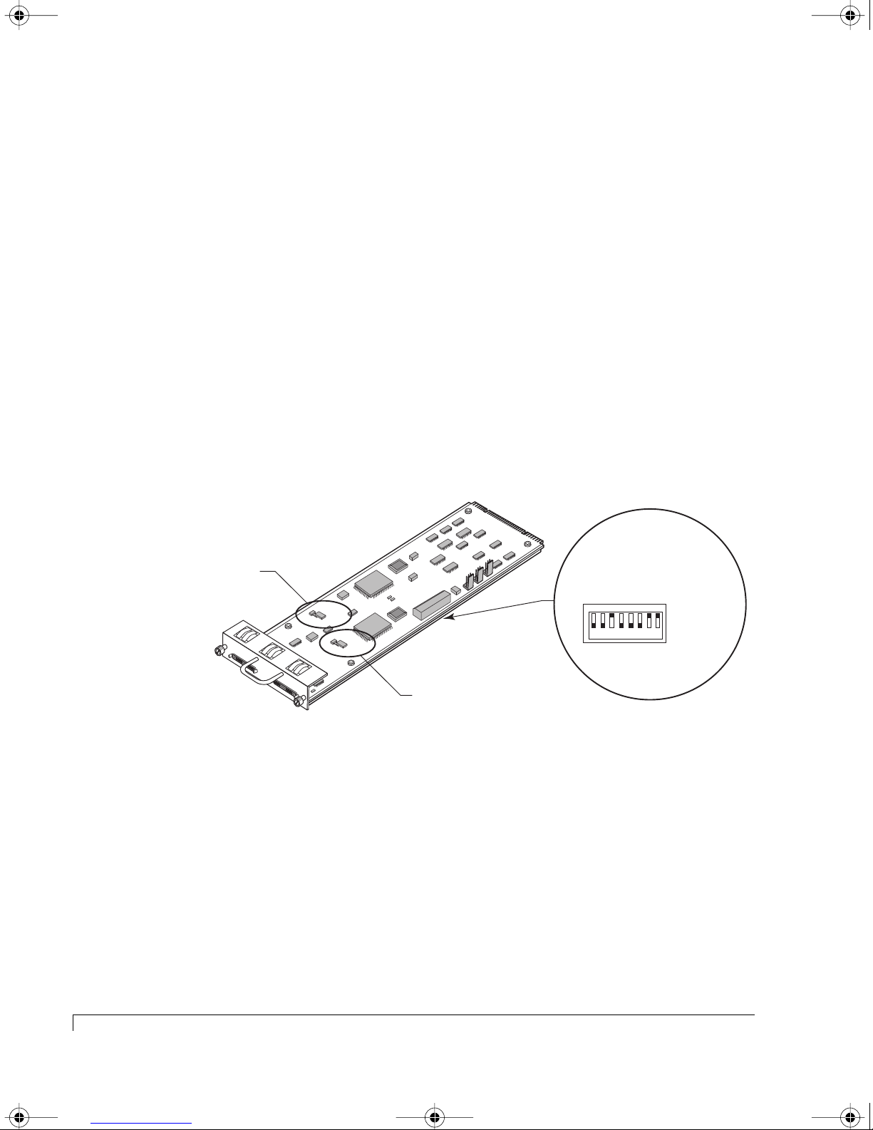
4100FS.book Page 42 Tuesday, July 8, 2003 4:35 PM
Chapter 3 - Setup and Installation
Enclosure Configuration
In this section, configurations are determined by the number of enclosures and
available number of drives. Configurations with drive numbers greater then the
primary RAID enclosure’s 12 drives, will require attaching a NexStor 4000S JBOD
enclosure(s). Follow the steps of procedures for your configuration to set the
switches, jumpers, and connect the SCSI data cables.
RAID - 12 Drive Configuration
The NexStor 4110FS/4120FS can be setup to provide up to a 12 disk drive storage
solution using the primary RAID enclosure only.
1 Remove the SAF-TE Disk I/O card installed in the enclosure. Loosen the two
thumb screws and pull the card from its slot location.
rt
a
Channel 1
Termination Jumper
Channel 1
Channel 2
n1
n2
atio
atio
1
ur
ur
re
re
onfig
onfig
C
C
RAID
Spa
BAUD RateSelect
CNFG 1
CNFG 2
SPARE 1
RAID
SPARE 2
CHANNEL -1
JP
8
T
E
R
M
T
I
O
N
A
D
T
A
I
S
I
D
O
A
D
N
B
L
J
U
E
M
P
E
R
JP
7
T
E
R
M
T
I
O
N
A
D
T
A
I
S
I
D
O
A
D
N
B
L
J
U
E
M
P
E
R
CHANNEL -2
BAUD SEL
DLY STRT
RMT STRT
Channel 2
Termination Jumper
Spa
S
RDA
A
S1BDDLR
0
0
1
1234 5678
2
lay D
e
R
D
M
t
ive S
r
D
rive Start
e
ot
m
e
UP (Off -1)
DOWN (On -0)
SAF-TE Disk I/O Card Switch and Jumper Locations
2 Locate the switches on the card and set them as described in the following
switch setting diagrams.
The switch settings will assign specific SCSI IDs to the drive slots as
indicated, and reserve IDs 6 and 7 for the RAID Controller(s), and IDs 8 or 15
for the SAF-TE processors.
There are two possible switch settings for this configuration. You may choose
either setting to fit your needs.
42
Enclosure Configuration
Page 55
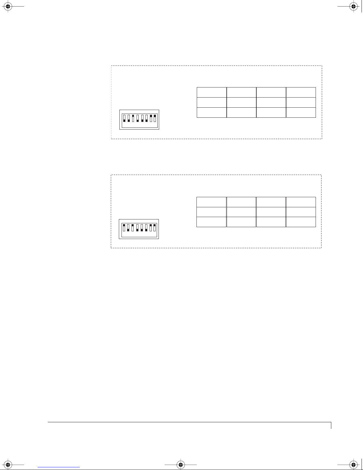
4100FS.book Page 43 Tuesday, July 8, 2003 4:35 PM
Chapter 3 - Setup and Installation
SAF-TE ID = 8/8
RAID Controllers = 6 & 7
Switch Settings
S
R
A
A
S1BDDLR
0
D
0
1
1234 5678
M
UP (1)
DOWN (0)
Switch Setting - Option 1 (NexStor 4110FS/4120FS)
SAF-TE ID = 15/15
RAID Controllers = 6 & 7
Switch Settings
S
RDA
A
S1BDDLR
0
0
1
1234 5678
M
UP (1)
DOWN (0)
Dual-Bus Mode
Slot 1
ID 1
Slot 2
ID 3
Slot 3 Slot 6 Slot 9 Slot 12
ID 5
Slot 4
ID 2
Slot 5
ID 4
ID 0
Drive IDs of the Drive Slots (Drive Channel Side)
Slot 7
Slot 8
ID 1
ID 3
ID 5
Slot 10
Slot 11
Dual-Bus Mode
Slot 1
ID 9
Slot 2
ID 11
Slot 3 Slot 6 Slot 9 Slot 12
ID 13
Slot 4
ID 10
Slot 5
ID 12
ID 14
Drive IDs of the Drive Slots (Drive Channel Side)
Slot 7
Slot 8
ID 9
ID 11
ID 13
Slot 10
Slot 11
ID 2
ID 4
ID 0
ID 10
ID 12
ID 14
Switch Setting - Option 2 (NexStor 4110FS/4120FS)
3 Re-install the SAF-TE Disk I/O card. Slide the card into the slot and ensure
that it seats completely. Secure the card by tighten the two thumb screws.
4 Connect a Fibre Channel data cable(s) from the host system(s) HBA(s) to the
primary RAID enclosure Host I/O card as indicated in “Topology Host
Cabling” on page 57.
This completes the RAID - 12 Drive Configuration setup, refer to “Topology Host
Cabling” on page 57 and “Powering On the Storage System” on page 70. Also,
refer to the AdminiStor software guide or the VT-100 software guide for
instructions on setting up and configuring the disk arrays.
RAID - 12 Drive Configuration
43
Page 56
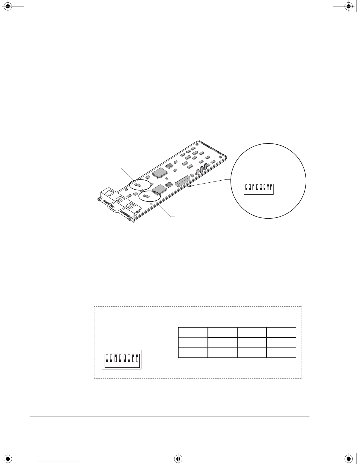
4100FS.book Page 44 Tuesday, July 8, 2003 4:35 PM
Chapter 3 - Setup and Installation
RAID - 24 Drive Configuration
The NexStor 4110FS/4120FS can be setup to provide up to a 24 disk drive storage
solution. In this configuration you will attach a NexStor 4000S JBOD enclosure to
the primary RAID enclosure which will extend the drive channels (12 drives per
channel).
1 Remove the SAF-TE Disk I/O card installed in the primary RAID enclosure.
Loosen the two thumb screws and pull the card from its slot location.
Channel 1
Termination Jumper
C
hannel 1
Channel 2
rt
a
2
rive Start
D
m
lay
e
e
R
D
M
t
ive S
r
D
e
ot
UP (Off -1)
DOWN (On -0)
n1
n2
atio
atio
1
ur
ur
re
re
onfig
onfig
C
C
RAID
Spa
BAUD RateSelect
C
N
C
F
N
G
F
1
G
S
R
2
P
A
A
ID
S
R
B
CHANNEL -1
JP8
T
E
R
M
T
I
O
N
A
D
T
A
I
S
I
D
O
A
D
N
B
L
J
U
E
M
P
E
R
J
P
7
T
E
R
M
T
I
O
N
A
D
T
A
I
S
I
D
O
A
D
N
B
L
J
U
E
M
P
E
R
CHANNEL -2
P
E
A
A
U
1
R
D
D
E
L
S
2
R
Y
S
M
E
L
T
T
S
R
T
T
R
T
Channel 2
Termination Jumper
Spa
S
RDA
A
S1BDDLR
0
0
1
1234 5678
SAF-TE Disk I/O Card Switch and Jumper Locations
2 Locate the switches on the card and set them as described in the following
switch setting diagram.
The switch settings will assign specific SCSI IDs to the drive slots as
indicated, and reserve IDs 6 and 7 for the RAID Controller(s), and IDs 8 or 15
for the SAF-TE processors.
SAF-TE ID = 8/8
RAID Controllers = 6 & 7
Switch Settings
S
R
A
A
S1BDDLR
0
D
0
1
1234 5678
M
UP (1)
DOWN (0)
Slot 1
ID 1
Slot 2
ID 3
Slot 3 Slot 6 Slot 9 Slot 12
ID 5
Slot 4
Slot 5
Switch Setting - Primary RAID Enclosure (NexStor 4110FS/4120FS)
Dual-Bus Mode
Slot 7
Slot 8
ID 1
ID 3
ID 5
ID 2
ID 4
ID 0
Drive IDs of the Drive Slots (Drive Channel Side)
Slot 10
Slot 11
ID 2
ID 4
ID 0
44
RAID - 24 Drive Configuration
Page 57
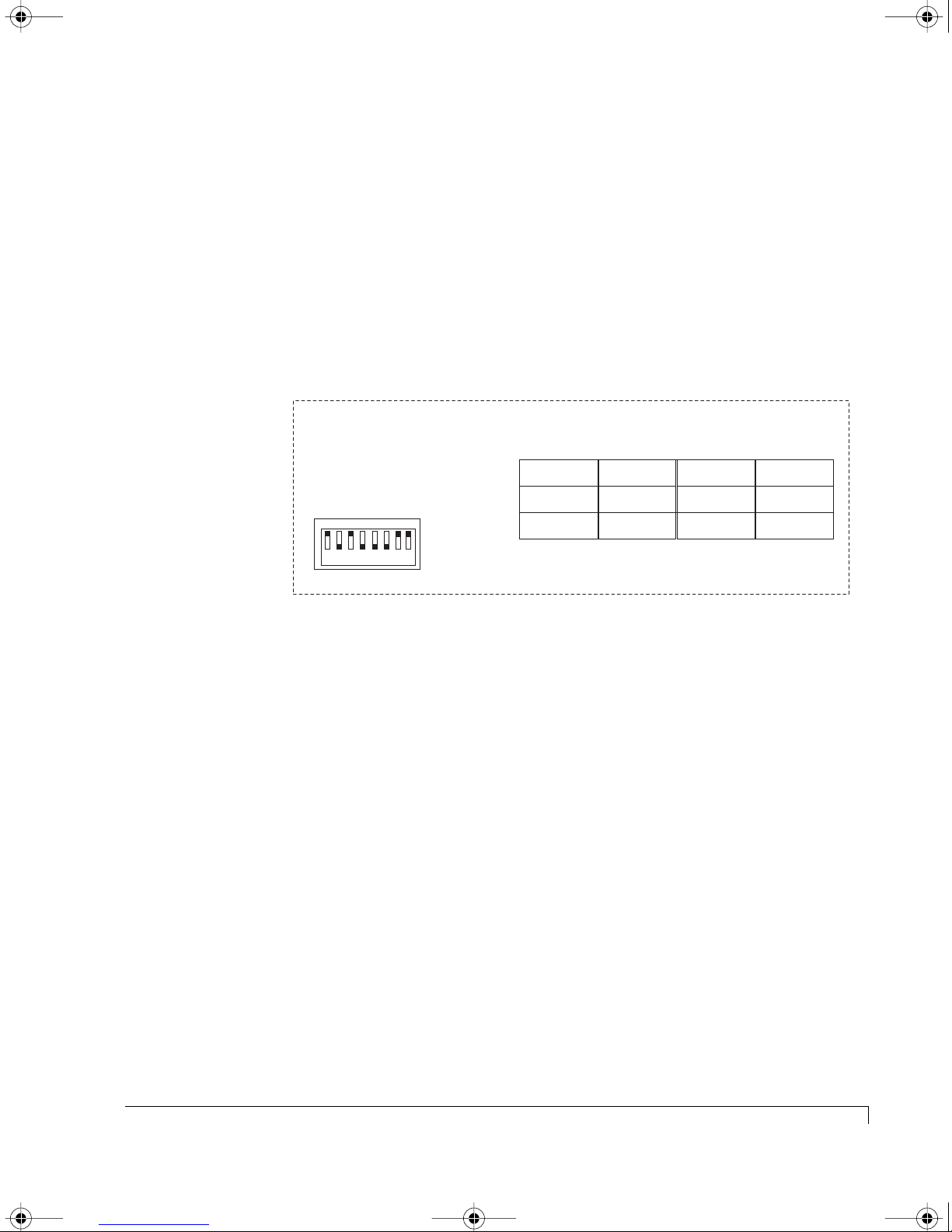
4100FS.book Page 45 Tuesday, July 8, 2003 4:35 PM
3 Re-install the SAF-TE Disk I/O card into the primary RAID enclosure. Slide
the card into the slot and ensure that it seats completely. Secure the card by
tighten the two thumb screws.
4 Remove the SAF-TE Disk I/O card installed in the daisy-chain enclosure
(NexStor 4000S). Loosen the two thumb screws and pull the card from its slot
location.
The daisy-chain enclosure will be configured to dual-bus mode. This
provides the drive channel expansion from the primary enclosures’ Disk I/O
channels. Set the switches as described in the following diagram.
Chapter 3 - Setup and Installation
SAF-TE ID = 15/15
RAID Controllers = 6 & 7
Switch Settings
S
R
A
A
S1BDDLR
0
D
0
1
1234 5678
M
UP (1)
DOWN (0)
Slot 1
ID 9
Slot 2
ID 11
Slot 3 Slot 6 Slot 9 Slot 12
ID 13
Dual-Bus Mode
Slot 4
ID 10
Slot 5
ID 12
ID 14
Drive IDs of the Drive Slots (Drive Channel Side)
Slot 7
Slot 8
ID 9
ID 11
ID 13
Slot 10
Slot 11
ID 10
ID 12
ID 14
Switch Setting - Dual-Bus Daisy-Chain Enclosure (NexStor 4000S)
5 (Daisy-chain Enclosure - NexStor 4000S) Change the jumper settings on the
SAF-TE Disk I/O card JP7 and JP8 as described.
Locate and add the two jumpers (JP7 and JP8), refer to the illustration on the
previous page. Add a jumper (installed on both pins) to JP8 for Channel 1
and JP7 for Channel 2.
This will ensure that the automatic termination feature functions properly.
6 Re-install the SAF-TE Disk I/O card into the daisy-chain enclosure. Slide the
card into the slot and ensure that it seats completely. Secure the card by
tighten the two thumb screws.
7 Connect the SCSI data cables from the NexStor 4110FS/4120FS SAF-TE Disk
I/O card to the NexStor 4000S enclosures’ SAF-TE Disk I/O card as indicated
in the following cabling diagram.
RAID - 24 Drive Configuration
45
Page 58
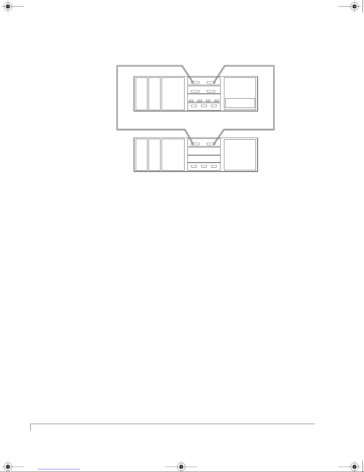
4100FS.book Page 46 Tuesday, July 8, 2003 4:35 PM
Chapter 3 - Setup and Installation
SAFTE Disk I/O
Chl 1
Power
Supply
Power
Supply
Cooling
Fans
SCSI Disk I/O
CTRL 1 CTRL 2SAFTE
Chl 0 Chl 3
Host I/O
P4P3P2P1
Chl 2
RAID Controller
NexStor 4110FS
SCSI Data Cable SCSI Data Cable
SAFTE Disk I/O
Chl 1
Power
Supply
Power
Supply
Cooling
Fans
CTRL 1 CTRL 2SAF-TE
Chl 2
NexStor 4000S
Enclosure Cabling Diagram (NexStor 4110FS used as example)
8 Connect a Fibre Channel data cable(s) from the host system(s) HBA(s) to the
primary RAID enclosure Host I/O card as indicated in “Topology Host
Cabling” on page 57.
This completes the RAID - 24 Drive Configuration setup, refer to “Topology Host
Cabling” on page 57 and “Powering On the Storage System” on page 70. Also,
refer to the AdminiStor software guide or the VT-100 software guide for
instructions on setting up and configuring the disk arrays.
46
RAID - 24 Drive Configuration
Page 59

4100FS.book Page 47 Tuesday, July 8, 2003 4:35 PM
RAID - 36 Drive Configuration
The NexStor 4110FS/4120FS can be setup to provide up to a 36 disk drive storage
solution. In this configuration you will attach two NexStor 4000S JBOD
enclosures to the primary RAID enclosure which will extend the drive channels
(12 drives per channel).
1 Remove the SAF-TE Disk I/O card installed in the primary RAID enclosure.
Loosen the two thumb screws and pull the card from its slot location.
Channel 1
Termination Jumper
Chapter 3 - Setup and Installation
rt
a
2
D
lay
e
R
D
M
t
ive S
r
D
rive Start
e
ot
m
e
UP (Off -1)
DOWN (On -0)
n1
n2
atio
atio
1
ur
ur
re
onfig
C
N
C
F
N
G
F
1
G
S
2
R
P
A
A
ID
S
R
B
CHANNEL -1
JP8
TERMINATION
TO
DISABLE
ADD JUMPER
JP
7
TERMINATION
TO
DISABLE
C
h
a
nn
e
l 1
C
h
a
n
n
e
l 2
ADD JUMPER
CHANNEL -2
P
E
A
A
1
U
R
D
D
E
L
S
2
R
Y
S
M
E
L
T
T
S
R
T
T
R
T
Channel 2
Termination Jumper
C
0
1234 5678
re
onfig
C
RAID
Spa
Spa
BAUD Rate Select
S
RDA
A
S1BDDLR
0
1
SAF-TE Disk I/O Card Switch and Jumper Locations
2 Locate the switches on the card and set them as described in the following
switch setting diagram.
The switch settings will assign specific SCSI IDs to the drive slots as
indicated, and reserve IDs 6 and 7 for the RAID Controller(s), and IDs 8 or 15
for the SAF-TE processors.
SAF-TE ID = 8/8
RAID Controllers = 6 & 7
Switch Settings
S
RDA
A
S1BDDLR
0
0
1
1234 5678
M
UP (1)
DOWN (0)
Slot 1
ID 1
Slot 2
ID 3
Slot 3 Slot 6 Slot 9 Slot 12
ID 5
Switch Setting - Primary RAID Enclosure (NexStor 4110FS/4120FS)
Dual-Bus Mode
Slot 4
Slot 5
ID 4
ID 0
Drive IDs of the Drive Slots (Drive Channel Side)
ID 2
Slot 7
Slot 8
ID 1
ID 3
ID 5
Slot 10
Slot 11
ID 2
ID 4
ID 0
RAID - 36 Drive Configuration
47
Page 60
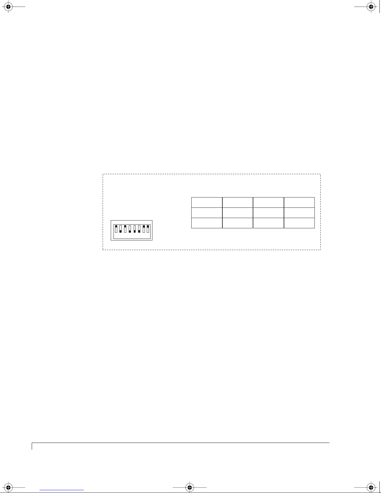
4100FS.book Page 48 Tuesday, July 8, 2003 4:35 PM
Chapter 3 - Setup and Installation
3 Re-install the SAF-TE Disk I/O card in the primary RAID enclosure. Slide the
card into the slot and ensure that it seats completely. Secure the card by
tighten the two thumb screws.
4 Remove the SAF-TE Disk I/O card installed in the first daisy-chain enclosure
(NexStor 4000S). Loosen the two thumb screws and pull the card from its slot
location.
The first daisy-chain enclosure will be configured to dual-bus mode. It
provides the drive channel expansion from the primary enclosures’ Disk I/O
channels. Set the switches as described in the following diagram.
SAF-TE ID = 15/15
RAID Controllers = 6 & 7
Switch Settings
S
R
A
A
S1BDDLR
0
D
0
1
1234 5678
M
UP (1)
DOWN (0)
Slot 1
ID 9
Slot 2
ID 11
Slot 3 Slot 6 Slot 9 Slot 12
ID 13
Dual-Bus Mode
Slot 4
ID 10
Slot 5
ID 12
ID 14
Drive IDs of the Drive Slots (Drive Channel Side)
Slot 7
Slot 8
ID 9
ID 11
ID 13
Slot 10
Slot 11
ID 10
ID 12
ID 14
Switch Setting - Dual-Bus Daisy-Chain Enclosure (NexStor 4000S)
5 (First Daisy-chain Enclosure - NexStor 4000S) Change the jumper settings on
the SAF-TE Disk I/O card JP7 and JP8 as described.
Locate and add the two jumpers (JP7 and JP8), refer to the illustration on the
previous page. Add a jumper (installed on both pins) to JP8 for Channel 1
and JP7 for Channel 2.
This will ensure that the automatic termination feature functions properly.
6 Re-install the SAF-TE Disk I/O card in the first daisy-chain enclosure. Slide
the card into the slot and ensure that it seats completely. Secure the card by
tighten the two thumb screws.
7 Remove the SAF-TE Disk I/O card installed in the second daisy-chain
enclosure (NexStor 4000S). Loosen the two thumb screws and pull the card
from its slot location.
48
RAID - 36 Drive Configuration
Page 61
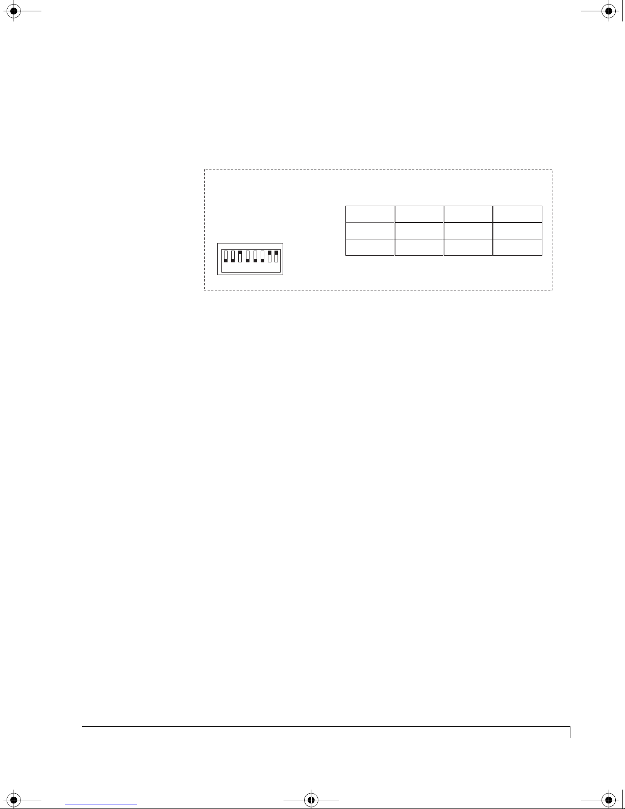
4100FS.book Page 49 Tuesday, July 8, 2003 4:35 PM
The second daisy-chain enclosure will be configured to single-bus mode. It
provides the drive channel expansion from the primary enclosures’ I/O card
Channel 0. Set the switches as described in the following diagram.
Chapter 3 - Setup and Installation
SAF-TE ID = 15
RAID Controllers = 6 & 7
Switch Settings
S
RDA
A
S1BDDLR
0
0
1
1234 5678
M
UP (1)
DOWN (0)
Slot 1
ID 1
Slot 2
ID 3
Slot 3 Slot 6 Slot 9 Slot 12
ID 5
Single-Bus Mode
Slot 4
ID 2
Slot 5
ID 4
ID 0
Drive IDs of the Drive Slots (Drive Channel Side)
Slot 7
Slot 8
Switch Setting - Single-Bus Daisy-Chain Enclosure (NexStor 4000S)
ID 9
ID 11
ID 13
Slot 10
Slot 11
ID 10
ID 12
ID 14
8 (Second Daisy-chain Enclosure - NexStor 4000S) Change the jumper settings
on the SAF-TE Disk I/O card JP7 and JP8 as described.
Locate and add the two jumpers (JP7 and JP8), refer to the illustration on the
previous page. Add a jumper (installed on both pins) to JP8 for Channel 1
and JP7 for Channel 2.
This will ensure that the automatic termination feature functions properly.
9 Re-install the SAF-TE Disk I/O card into the second daisy-chain enclosure.
Slide the card into the slot and ensure that it seats completely. Secure the
card by tighten the two thumb screws.
10 (Second Daisy-chain Enclosure - NexStor 4000S) Install the Single-Bus
Module in the Controller 1 slot.
a Remove the Controller Cover plate. Loosen the four thumb screws and
pull the cover plate from the enclosure.
b Slide the Single-Bus Module in the Controller 1 (lower) slot, and secure it
by pressing the latches into place.
RAID - 36 Drive Configuration
49
Page 62
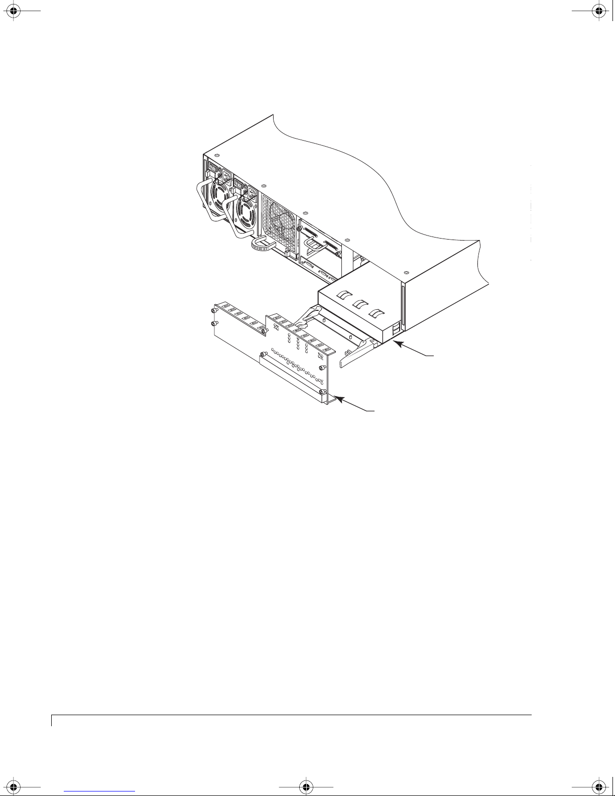
4100FS.book Page 50 Tuesday, July 8, 2003 4:35 PM
Chapter 3 - Setup and Installation
T
E
R
M
T
O
P
S
O
A
U
W
D
P
E
D
JP1
P
R
L
J
Y
U
M
P
E
JP3
I
N
JP3
A
T
I
O
N
E
I
N
A
T
I
O
N
E
C
H
A
N
N
E
L
-1
J
P
5
T
E
R
M
T
O
P
O
S
W
A
U
D
P
E
D
P
R
L
J
Y
U
M
P
E
J
R
P
8
T
E
R
M
T
I
O
N
A
D
T
A
I
S
I
D
O
A
D
N
B
L
J
U
E
M
P
E
R
JP7
T
E
R
M
T
JP6
I
O
N
A
D
T
A
I
S
I
D
O
A
D
N
B
L
J
U
E
M
P
E
R
T
E
R
M
T
O
P
O
S
W
A
U
D
P
E
D
P
R
L
J
Y
U
M
C
P
E
H
R
A
N
N
E
L
-
2
R
T
E
R
M
T
O
P
S
O
A
U
W
D
P
E
D
JP1
P
R
L
J
Y
U
M
T
JP2
E
R
M
B
L
R
M
B
L
P
E
T
R
O
D
A
I
S
D
A
D
J
JP4
U
M
P
E
R
T
JP2
E
T
O
D
A
I
S
D
A
D
J
JP4
U
M
P
E
R
C
N
C
F
N
G
F
1
G
S
2
R
P
A
A
ID
S
R
B
P
E
A
A
1
U
R
D
D
E
L
S
R
Y
2
S
M
E
L
T
T
S
R
T
T
R
T
Single-Bus
Module
Cover Plate
Single-Bus Module Installation
c Re-install the Controller Cover plate. Tighten the four thumb screws, do
not overtighten.
11 Connect the SCSI data cables from the NexStor 4110FS/4120FS to the two
NexStor 4000S enclosures as indicated in the following enclosure cabling
diagram.
NOTE: When connecting the Single-Bus NexStor 4000S enclosure to the
primary RAID enclosure, you will connect to the Channel 0
connector on the Host SCSI I/O card installed in the NexStor
4110FS/4120FS enclosure.
50
RAID - 36 Drive Configuration
Page 63
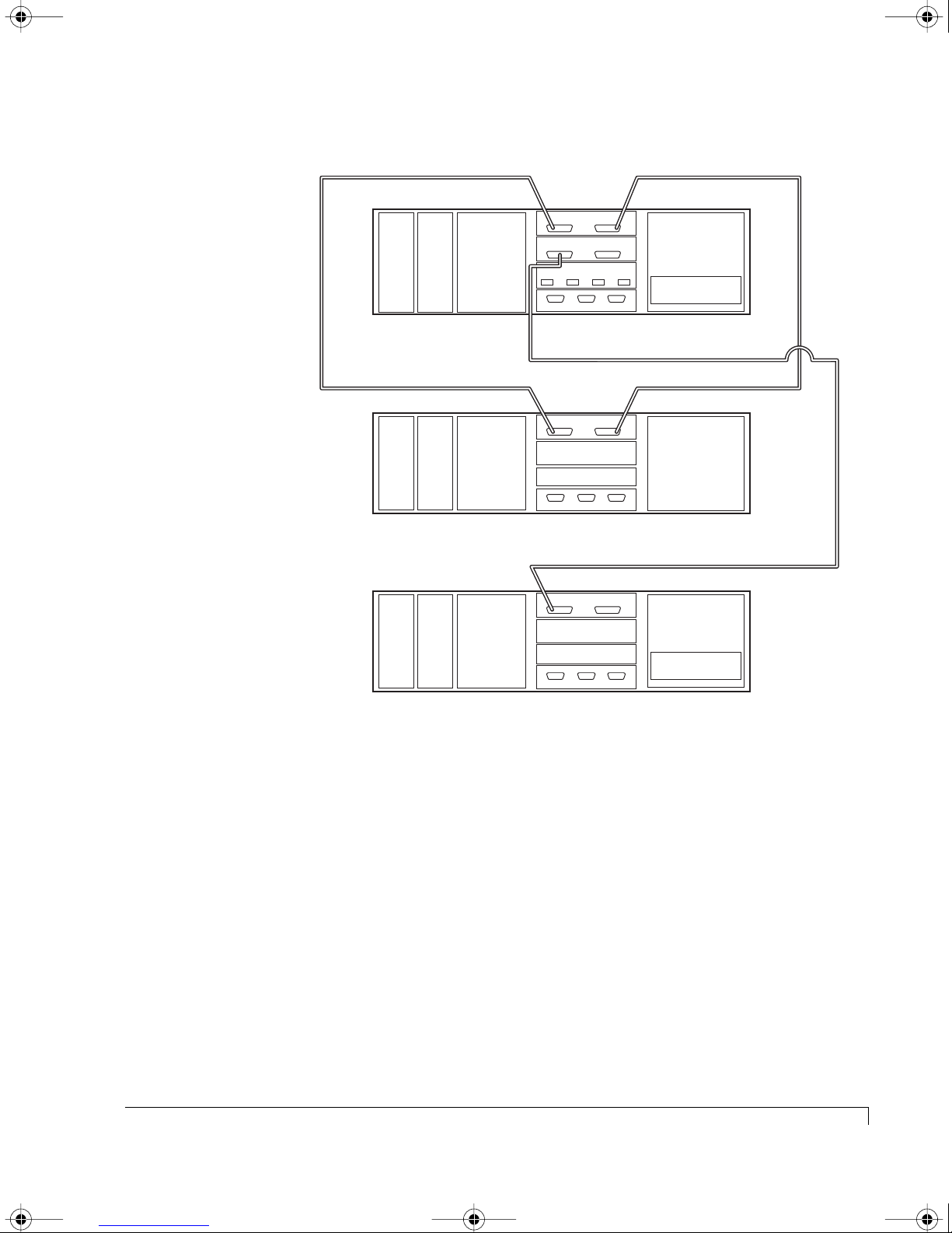
4100FS.book Page 51 Tuesday, July 8, 2003 4:35 PM
Chapter 3 - Setup and Installation
Power
Supply
Power
Supply
Power
Supply
SCSI Data Cable
Power
Supply
Power
Supply
Power
Supply
SAFTE Disk I/O
Cooling
Fans
CTLR 1 CTLR 2SAF-TE
NexStor 4110FS
SAFTE Disk I/O
Cooling
Fans
Ctlr 1 Ctlr 2SAF-TE
NexStor 4000S (Dual-Bus)
SAFTE Disk I/O
Cooling
Fans
Ctlr 1 Ctlr 2SAF-TE
Chl 1
I/O
Chl 0 Chl 3
Host I/O
P4 P3P2P1
Chl 1
Chl 1
SCSI Data Cable
Chl 2
RAID Controller
Chl 2
SCSI Data Cable
Chl 2
Single Bus
Module
NexStor 4000S (Single-Bus)
Enclosure Cabling Diagram (NexStor 4110FS used as example)
12 Connect a Fibre Channel data cable(s) from the host system(s) HBA(s) to the
primary RAID enclosure Host I/O card as indicated in “Topology Host
Cabling” on page 57.
This completes the RAID - 36 Drive Configuration setup, refer to “Topology Host
Cabling” on page 57 and “Powering On the Storage System” on page 70. Also,
refer to the AdminiStor software guide or the VT-100 software guide for
instructions on setting up and configuring the disk arrays.
RAID - 36 Drive Configuration
51
Page 64
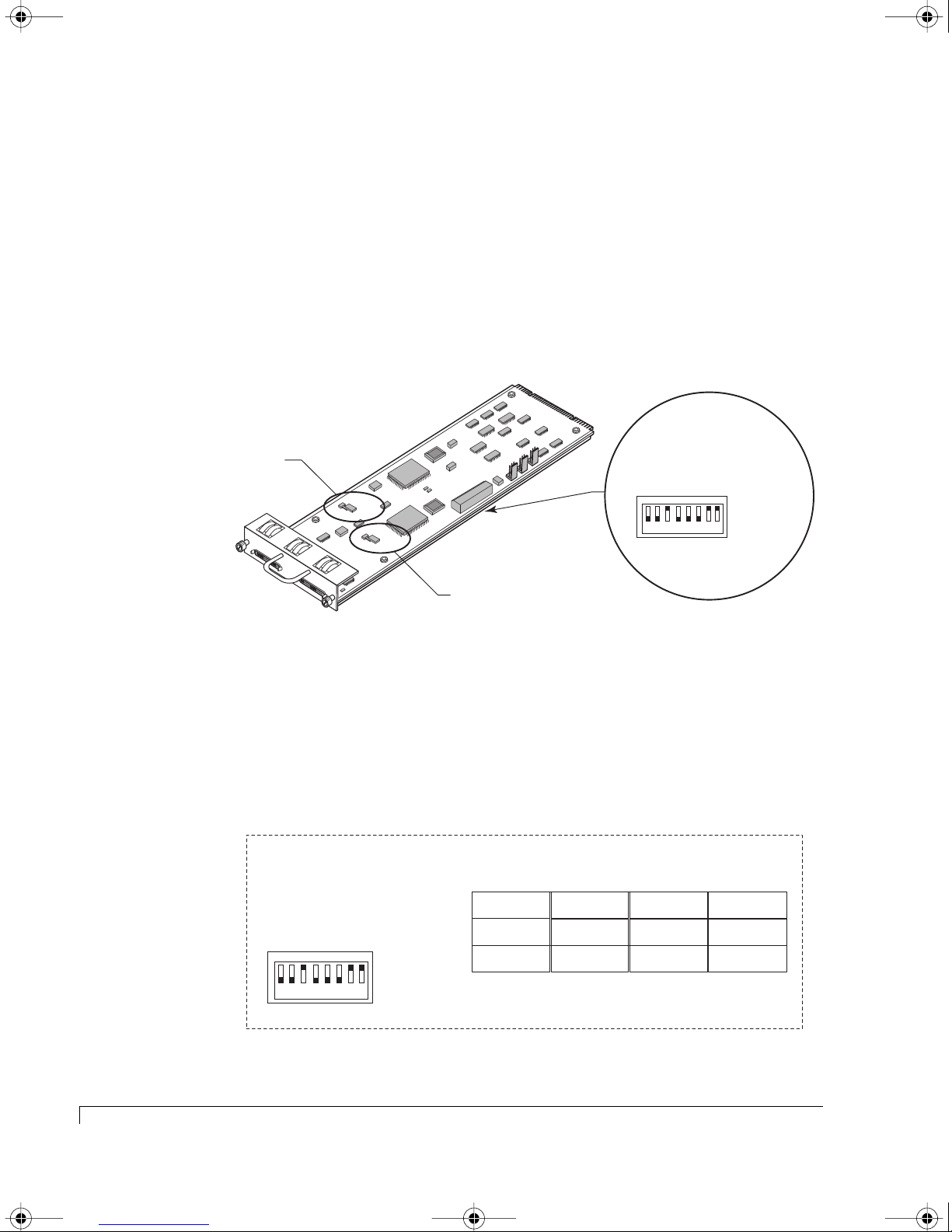
4100FS.book Page 52 Tuesday, July 8, 2003 4:35 PM
Chapter 3 - Setup and Installation
RAID - 48 Drive Configuration
The NexStor 4110FS/4120FS can be setup to provide up to a 48 disk drive storage
solution. In this configuration you will attach three NexStor 4000S JBOD
enclosures to the primary RAID enclosure which will extend the drive channels
(12 drives per channel).
1 Remove the SAF-TE Disk I/O card installed in the primary RAID enclosure.
Loosen the two thumb screws and pull the card from its slot location.
Channel 1
Termination Jumper
C
h
a
nn
e
l 1
C
rt
a
2
rive Start
D
lay
e
e
R
D
M
t
ive S
r
D
e
ot
m
UP (Off -1)
DOWN (On -0)
n1
n2
atio
atio
1
ur
ur
re
onfig
C
N
C
F
N
G
F
1
G
S
2
R
P
A
A
ID
S
R
B
CHANNEL -1
JP8
TERMINATION
TO
DISABLE
ADD JUMPER
JP
7
TERMINATION
TO
DISABLE
ADD JUMPER
CHANNEL -2
h
a
n
n
el 2
P
E
A
A
1
U
R
D
D
E
L
S
2
R
Y
S
M
E
L
T
T
S
R
T
T
R
T
Channel 2
Termination Jumper
C
0
1234 5678
re
onfig
C
RAID
Spa
BAUD Rate Select
Spa
S
RDA
A
S1BDDLR
0
1
SAF-TE Disk I/O Card Switch and Jumper Locations
2 Locate the switches on the card and set them as described in the following
switch setting diagram.
The switch settings will assign specific SCSI IDs to the drive slots as
indicated, and reserve IDs 6 and 7 for the RAID Controller(s), and IDs 8 or 15
for the SAF-TE processors.
SAF-TE ID = 8/8
RAID Controllers = 6 & 7
Switch Settings
S
R
A
A
S1BDDLR
0
D
0
1
M
UP (1)
1234 5678
DOWN (0)
Switch Setting - Primary RAID Enclosure (NexStor 4110FS/4120FS)
Slot 1
ID 1
Slot 2
ID 3
Slot 3 Slot 6 Slot 9 Slot 12
ID 5
Slot 4
Slot 5
Dual-Bus Mode
Slot 7
Slot 8
ID 1
ID 3
ID 5
ID 2
ID 4
ID 0
Drive IDs of the Drive Slots (Drive Channel Side)
Slot 10
Slot 11
ID 2
ID 4
ID 0
52
RAID - 48 Drive Configuration
Page 65
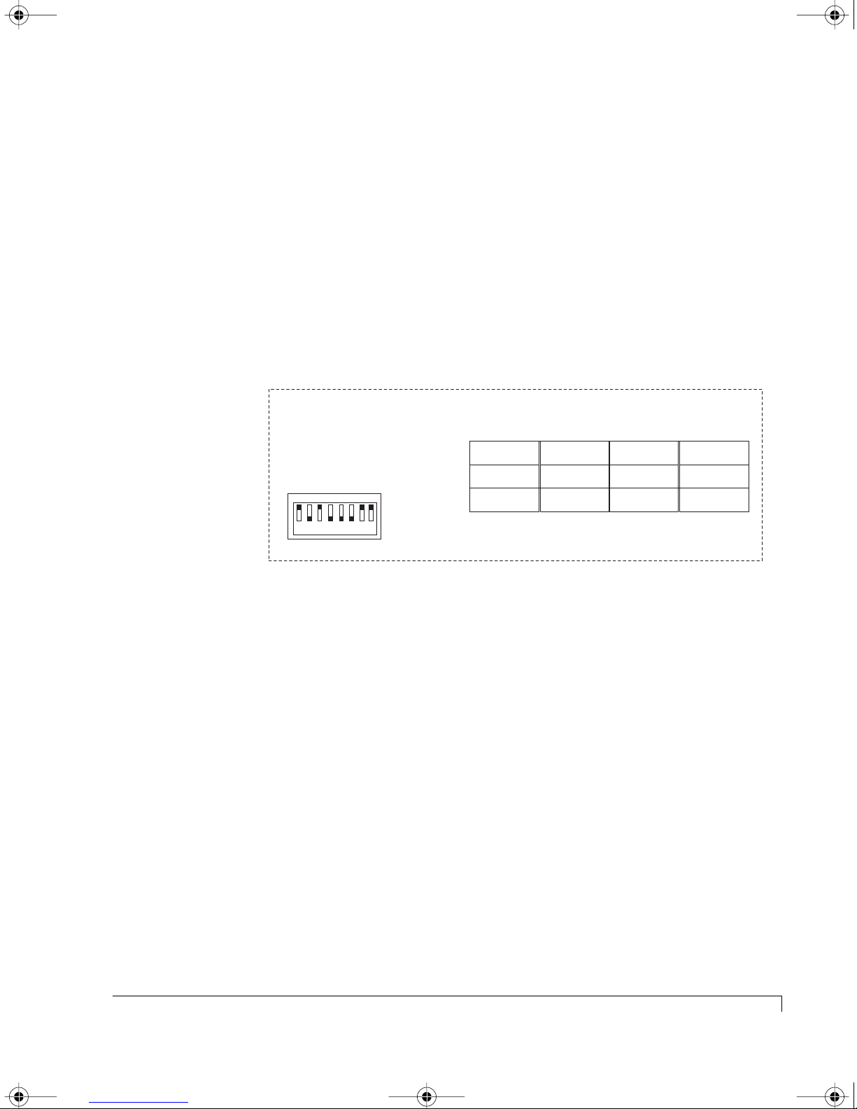
4100FS.book Page 53 Tuesday, July 8, 2003 4:35 PM
3 Re-install the SAF-TE Disk I/O card in the primary RAID enclosure. Slide the
card into the slot and ensure that it seats completely. Secure the card by
tighten the two thumb screws.
4 Remove the SAF-TE Disk I/O card installed in the first daisy-chain enclosure
(NexStor 4000S). Loosen the two thumb screws and pull the card from its slot
location.
The first daisy-chain enclosure will be configured to dual-bus mode. This
provides the drive channel expansion from the primary enclosures’ Disk I/O
channels. Set the switches as described in the following diagram.
Chapter 3 - Setup and Installation
SAF-TE ID = 15/15
RAID Controllers = 6 & 7
Switch Settings
S
R
A
S1BDDLR
0
DA0
1
1234 5678
M
UP (1)
DOWN (0)
Slot 1
ID 9
Slot 2
ID 11
Slot 3 Slot 6 Slot 9 Slot 12
ID 13
Dual-Bus Mode
Slot 4
ID 10
Slot 5
ID 12
ID 14
Drive IDs of the Drive Slots (Drive Channel Side)
Slot 7
Slot 8
ID 9
ID 11
ID 13
Slot 10
Slot 11
ID 10
ID 12
ID 14
Switch Setting - Dual-Bus Daisy-Chain Enclosure (NexStor 4000S)
5 (First Daisy-chain Enclosure - NexStor 4000S) Change the jumper settings on
the SAF-TE Disk I/O card JP7 and JP8 as described.
Locate and add the two jumpers (JP7 and JP8), refer to the illustration on the
previous page. Add a jumper (installed on both pins) to JP8 for Channel 1
and JP7 for Channel 2.
This will ensure that the automatic termination feature functions properly.
6 Re-install the SAF-TE Disk I/O card in the first daisy-chain enclosure. Slide
the card into the slot and ensure that it seats completely. Secure the card by
tighten the two thumb screws.
7 Remove the SAF-TE Disk I/O card installed in the second and third
daisy-chain enclosures (NexStor 4000S). Loosen the two thumb screws and
pull the card from its slot location.
RAID - 48 Drive Configuration
53
Page 66
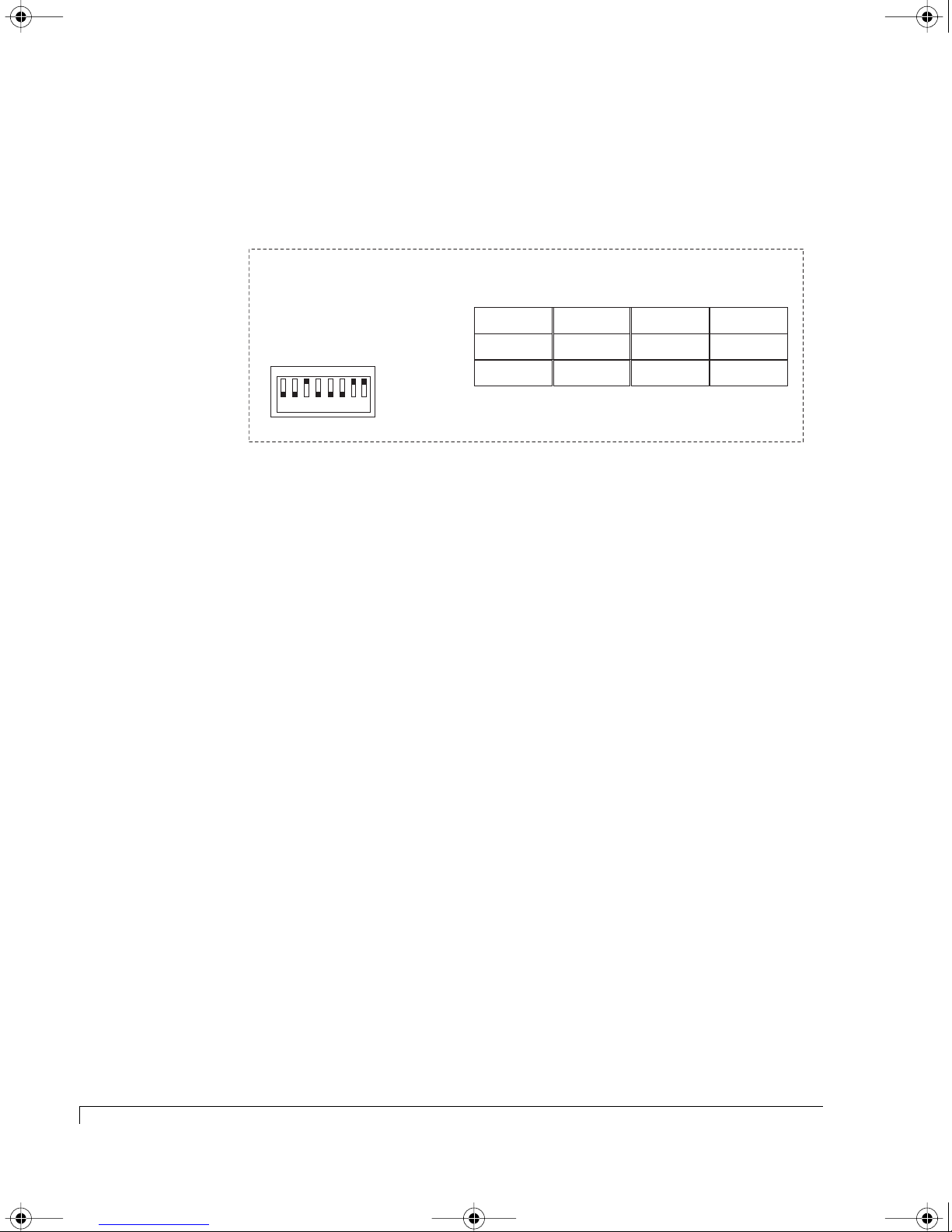
4100FS.book Page 54 Tuesday, July 8, 2003 4:35 PM
Chapter 3 - Setup and Installation
The second and third daisy-chain enclosures will be configured to single-bus
mode through their switch settings. Therefore, the switch setting is the same
for both of these daisy-chained enclosures.
SAF-TE ID = 15
RAID Controllers = 6 & 7
Switch Settings
RDA
A
0
1
1234 5678
S
S1BDDLR
0
M
UP (1)
DOWN (0)
Single-Bus Mode
Slot 1
ID 1
Slot 2
ID 3
Slot 3 Slot 6 Slot 9 Slot 12
ID 5
Slot 4
ID 2
Slot 5
ID 4
ID 0
Drive IDs of the Drive Slots (Drive Channel Side)
Slot 7
Slot 8
ID 9
ID 11
ID 13
Slot 10
Slot 11
ID 10
ID 12
ID 14
Switch Setting - Single-Bus Daisy-Chain Enclosure (NexStor 4000S)
8 (Second & Third Daisy-chain Enclosure - NexStor 4000S) Change the jumper
settings on the SAF-TE Disk I/O card JP7 and JP8 as described.
Locate and add the two jumpers (JP7 and JP8), refer to the illustration on the
previous page. Add a jumper (installed on both pins) to JP8 for Channel 1
and JP7 for Channel 2.
This will ensure that the automatic termination feature functions properly.
9 Re-install the SAF-TE Disk I/O cards in each enclosure. Slide the card into the
slot and ensure that it seats completely. Secure the card by tighten the two
thumb screws.
10 (Second & Third Daisy-chain Enclosure) Install the Single-Bus Module in the
Controller 1 “lower” slot in both of these enclosures.
a Remove the Controller Cover plate. Loosen the four thumb screws and
pull the cover plate from the enclosure.
b Slide the Single-Bus Module in the Controller 1 (lower) slot, and secure it
by pressing the latches into place.
54
RAID - 48 Drive Configuration
Page 67
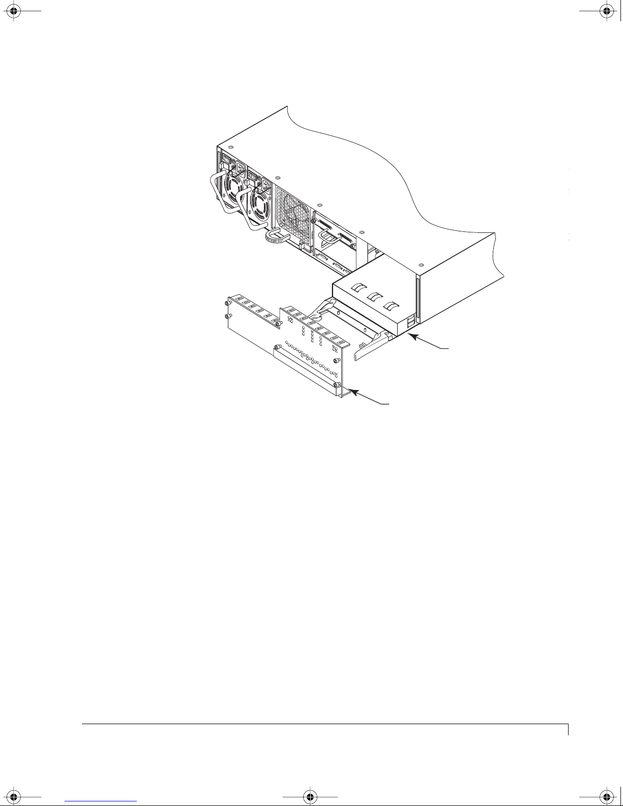
4100FS.book Page 55 Tuesday, July 8, 2003 4:35 PM
Chapter 3 - Setup and Installation
T
E
R
M
T
O
P
S
O
A
U
W
D
P
E
D
JP1
P
R
L
J
Y
U
M
P
E
R
JP3
M
I
N
JP3
A
T
I
O
N
L
E
M
I
N
A
T
I
O
N
L
E
C
H
A
N
N
E
L
-
1
J
P
5
T
E
R
M
T
O
P
O
S
A
W
U
D
P
E
D
P
R
L
J
Y
U
M
P
E
J
R
P
8
T
E
R
M
T
I
O
N
A
D
T
A
I
S
I
D
O
A
D
N
B
L
J
U
E
M
P
E
R
J
P
7
T
E
R
M
T
J
I
O
N
P
A
D
T
A
I
6
S
I
D
O
A
D
N
B
L
J
U
E
M
P
E
R
T
E
R
M
T
O
P
O
S
A
W
U
D
P
E
D
P
R
L
J
Y
U
M
C
P
E
H
R
A
N
N
E
L
2
T
E
R
M
T
O
P
S
O
A
U
W
D
P
E
D
JP1
P
R
L
J
Y
T
E
R
I
S
A
B
E
R
T
E
R
I
S
A
B
E
R
U
M
JP2
P
E
T
R
O
D
A
D
D
J
JP4
U
M
P
JP2
T
O
D
A
D
D
J
JP4
U
M
P
C
N
C
F
N
G
F
1
G
S
2
R
P
A
A
ID
S
R
B
P
E
A
A
1
U
R
D
D
E
L
S
2
R
Y
M
E
S
L
T
T
S
R
T
T
R
T
Single-Bus
Module
Cover Plate
Single-Bus Module Installation
c Re-install the Controller Cover plate. Tighten the four thumb screws, do
not overtighten.
11 Connect the SCSI data cables from the NexStor 4110FS/4120FS to the three
NexStor 4000S enclosures as indicated in the following cabling diagram.
NOTE: When connecting the Single-Bus NexStor 4000S enclosure to the
primary RAID enclosure you will connect it to the Channel 0 and
Channel 1 connectors on the Host SCSI I/O card installed in the
NexStor 4110FS/4120FS enclosure.
RAID - 48 Drive Configuration
55
Page 68
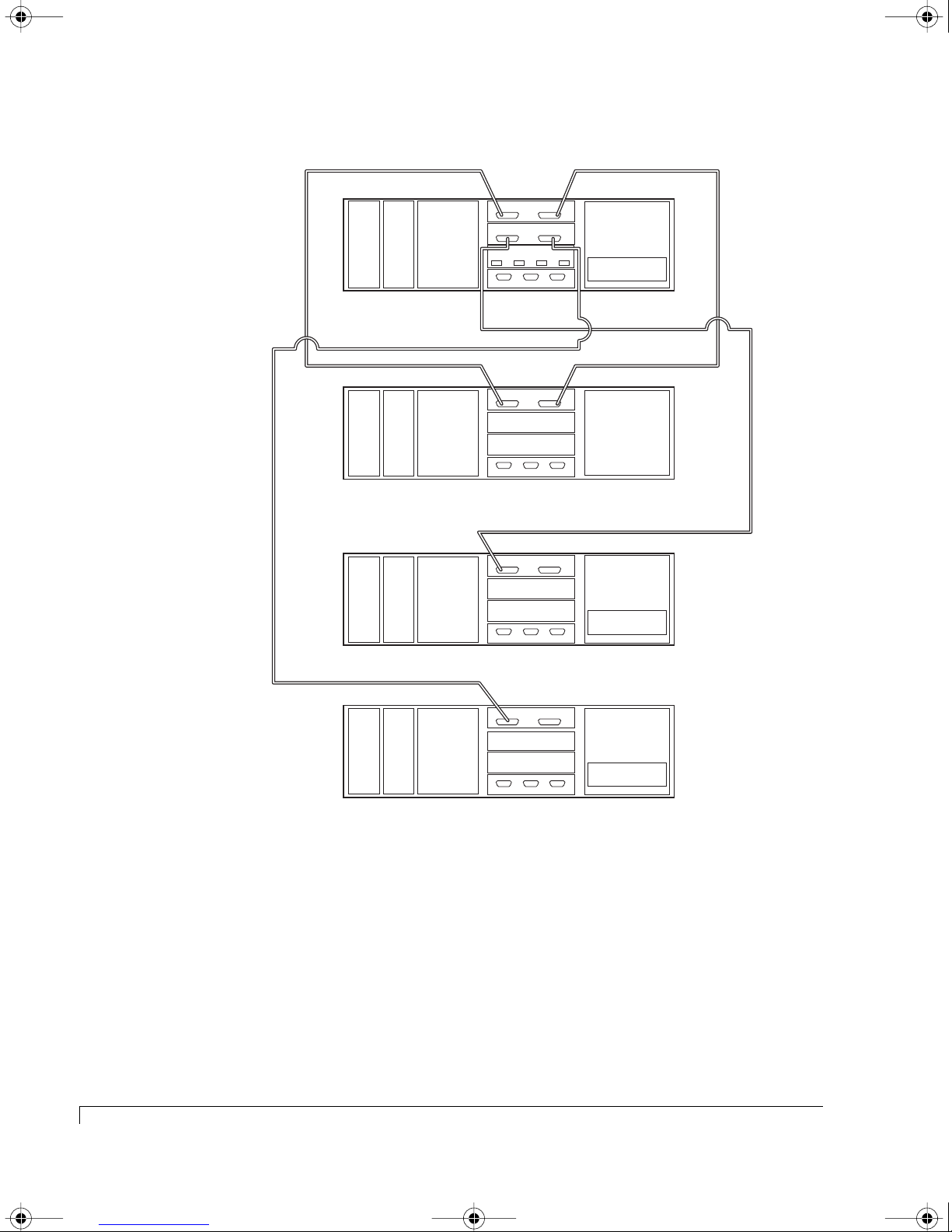
4100FS.book Page 56 Tuesday, July 8, 2003 4:35 PM
Chapter 3 - Setup and Installation
SCSI Data Cable
Power
Supply
Power
Supply
Power
Supply
SCSI Data Cable
Power
Supply
Power
Supply
Power
Supply
Cooling
Fans
CTLR 1 CTLR 2SAF-TE
NexStor 4110FS
Cooling
Fans
CTRL 1 CTLR 2SAF-TE
NexStor 4000S (Dual-Bus)
Cooling
Fans
CTLR 1 CTLR 2SAF-TE
NexStor 4000S (Single-Bus)
SAFTE Disk I/O
Chl 1
I/O
Chl 0 Chl 3
Host I/O
P4 P3P2P1
SAFTE Disk I/O
Chl 1
SAFTE Disk I/O
Chl 1
SCSI Data Cable
Chl 2
RAID Controller
Chl 2
SCSI Data Cable
Chl 2
Single Bus
Module
56
12 Connect a Fibre Channel data cable(s) from the host system(s) HBA(s) to the
primary RAID enclosure Host I/O card as indicated in “Topology Host
Cabling” on page 57.
This completes the RAID - 48 Drive Configuration setup, refer to “Topology Host
Cabling” on page 57 and “Powering On the Storage System” on page 70. Also,
refer to the AdminiStor software guide or the VT-100 software guide for
instructions on setting up and configuring the disk arrays.
RAID - 48 Drive Configuration
Power
Supply
Power
Supply
Cooling
Fans
CTLR 1 CTLR 2SAF-TE
NexStor 4000S (Single-Bus)
Enclosure Cabling Diagram
SAFTE Disk I/O
Chl 1
Chl 2
Single Bus
Module
Page 69

4100FS.book Page 57 Tuesday, July 8, 2003 4:35 PM
Topology Host Cabling
This section provides instructions and diagrams for the physical cabling of the
primary RAID enclosure and your host system(s).
by the number of RAID Controllers installed and the specific operating mode.
They are further categorized by the condition of the internal hubs.
Basic Connection Instructions
1 Install your host bus adapter(s) into the host system(s). Refer to your HBA
user’s guide and any applicable nStor Attach Kit for specific details.
2 For multiple LUN support, ensure that your host operating system is properly
configured to support this feature. Refer to your host operating system user’s
guide for information on how to perform this procedure.
3 Connect the Fibre Channel data cables. Refer to the topology described for
your installation on the following pages, and cable your system based on the
diagrams shown.
Chapter 3 - Setup and Installation
The topologies are determined
a Connect the required Fibre Channel data cable(s) to the host system’s
Fibre Channel host bus adapter port connector(s).
b Connect the other end of those Fibre Channel data cable(s) to the storage
enclosure Host Channel ports on the Host I/O card(s) as indicated.
4 Continue now with “Powering On the Storage System” on page 70.
5 After powering up all the system(s), you may need to set the operating
mode.
By default the RAID Controller’s operating mode are set to “Active-Active
Single Port.” Access the AdminiStor software or VT-100 on-board software
and make the necessary changes to the operating mode. The selections will
be:
• Stand-Alone Dual Port
• Active-Active Single Port
• Active-Active Dual Port
• Active-Passive Dual Port
6 Using AdminiStor or the VT-100 interface, configure the disk arrays as
desired.
Topology Host Cabling
57
Page 70
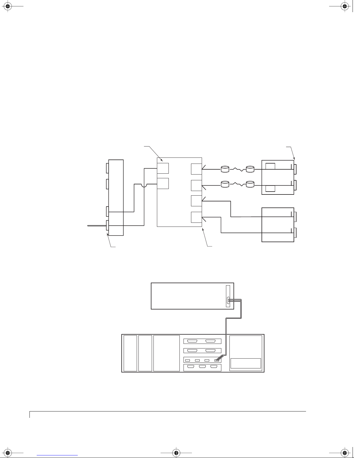
4100FS.book Page 58 Tuesday, July 8, 2003 4:35 PM
Chapter 3 - Setup and Installation
Stand-Alone Dual Port:Host Cabling
This topology is chosen when the desired application requires a low cost entry
level, fault-tolerant disk storage solution. This solution provides a single controller
configuration that supports dual ported access with the internal hubs either enabled
or disabled. With the internal hub disabled, it is ideal in a host direct attached
application or SAN environments when connected to an external switch/hub.
Setup for a Single Host- One HBA (Hubs Disabled)
Connect the Fibre Channel data cables as described in the following diagrams.
Host System #1
HBA 1
Controller FC Host Ports
HOST I/O
P1
P2
P4
P3
T= Location of internal termination
Host I/O Connectors
RAID Controller
FC1
Active
Active
FC2
Controller 1 (A)
Disk
CH1
Disk
CH2
Disk
CH0
Disk
CH3
T
T
T
T
Controller Disk Ports
Logical Diagram - Single Host with a Single HBA (Hubs Disabled)
FC HBA 1
Host Computer #1
Drives 7 - 12
Drives 1 - 6
Drive I/O Connectors
SEP
SEP
SAF-TE Disk I/O
Host SCSI I/O
T
CH 1 CH 2
T
T
CH 0 CH 3
T
Host Cabling Diagram - Single Host with a Single HBA (Hubs Disabled)
58
Stand-Alone Dual Port:Host Cabling
Power
Supply
Power
Supply
Cooling
Fans
Fibre Channel Data Cable
SAFTE Disk I/O
Chl 1 Chl 2
SCSI Disk I/O
Chl 0 Chl 3
Host I/O
Ctlr 1 Ctlr 2SAF-TE
NexStor 4110FS
Connect to P3
P4 P3P2P1
RAID Controller
Page 71
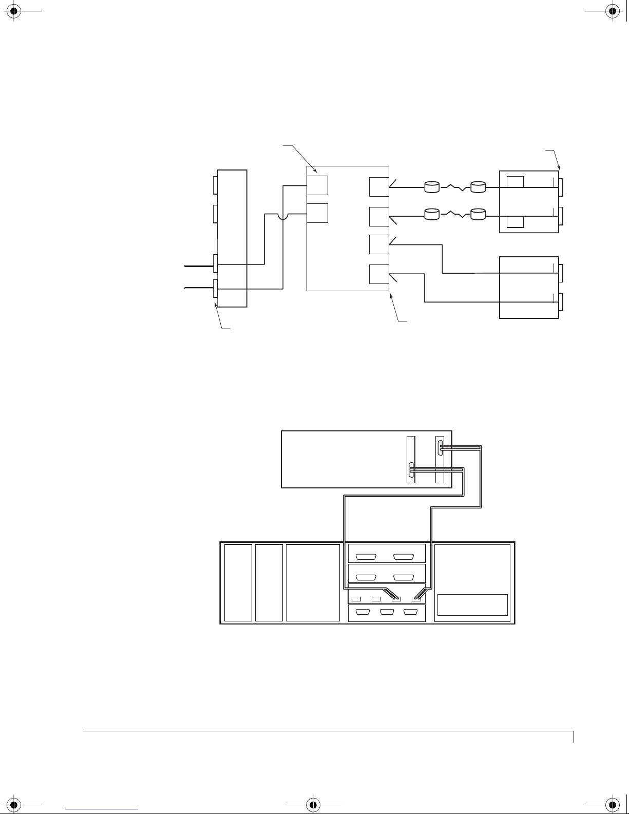
4100FS.book Page 59 Tuesday, July 8, 2003 4:35 PM
Setup for a Single Host - Two HBAs (Hubs Disabled)
Connect the Fibre Channel data cables as described in the following diagrams.
Chapter 3 - Setup and Installation
Host System #1
HBA 2
Host System #1
HBA 1
Controller FC Host Ports
HOST I/O
P1
P2
P4
P3
RAID Controller
Drives 7 - 12
Drives 1 - 6
Controller Disk Ports
Host I/O Connectors
FC1
Active
Active
FC2
Controller 1 (A)
T= Location of internal termination
Disk
CH1
Disk
CH2
Disk
CH0
Disk
CH3
T
T
T
T
Logical Diagram - Single Host with Two HBAs (Hubs Disabled)
FC HBA 2 FC HBA 1
Drive I/O Connectors
SEP
SEP
SAF-TE Disk I/O
Host SCSI I/O
T
CH 1 CH 2
T
T
CH 0 CH 3
T
Host Computer #1
Fibre Channel Data Cable
Connect to P3
RAID Controller
Power
Supply
Fibre Channel Data Cable
Connect to P4
Power
Supply
Cooling
Fans
SAFTE Disk I/O
Chl 1 Chl 2
SCSI Disk I/O
Chl 0 Chl 3
Host I/O
Ctlr 1 Ctlr 2SAF-TE
P4 P3P2P1
NexStor 4110FS
Host Cabling Diagram - Single Host with Two HBAs (Hubs Disabled)
Stand-Alone Dual Port:Host Cabling
59
Page 72
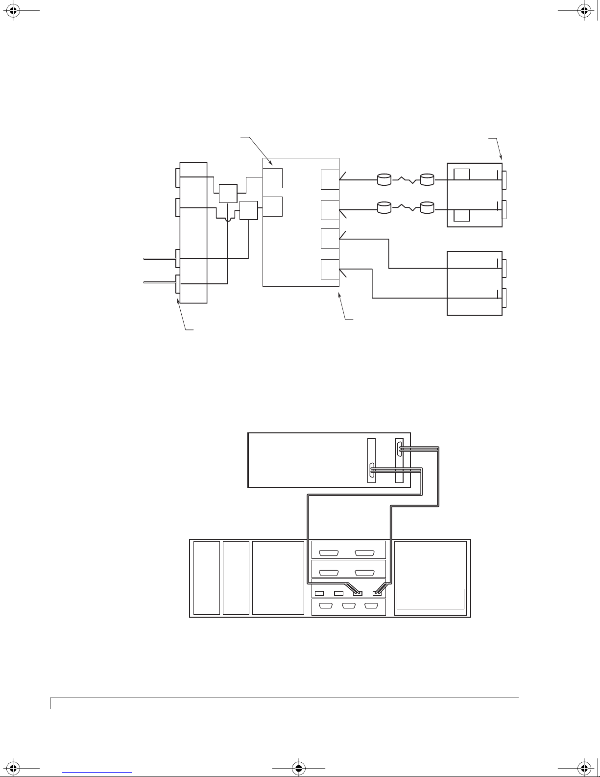
4100FS.book Page 60 Tuesday, July 8, 2003 4:35 PM
Chapter 3 - Setup and Installation
Setup for a Single Host - Two HBAs (Hubs Enabled)
Connect the Fibre Channel data cables as described in the following diagrams.
Host System #1
HBA 2
Host System #1
HBA 1
Controller FC Host Ports
HOST I/O
P1
P2
P4
P3
Host I/O Connectors
RAID Controller
Drives 7 - 12
FC1
Active
Disk
CH1
T
HUB
Active
FC2
HUB
Controller 1 (A)
T= Location of internal termination
Disk
CH2
Disk
CH0
Disk
CH3
T
T
T
Controller Disk Ports
Drives 1 - 6
Logical Diagram - Single Host with Two HBAs (Hubs Enabled)
Drive I/O Connectors
SEP
SEP
SAF-TE Disk I/O
Host SCSI I/O
T
CH 1 CH 2
T
T
CH 0 CH 3
T
60
Stand-Alone Dual Port:Host Cabling
FC HBA 2 FC HBA 1
Host Computer #1
Fibre Channel Data Cable
Connect to P3
RAID Controller
Power
Supply
Fibre Channel Data Cable
Connect to P4
Power
Supply
Cooling
Fans
SAFTE Disk I/O
Chl 1 Chl 2
SCSI Disk I/O
Chl 0 Chl 3
Host I/O
Ctlr 1 Ctlr 2SAF-TE
P4 P3P2P1
NexStor 4110FS
Host Cabling Diagram - Single Host with Two HBAs (Hubs Enabled)
Page 73
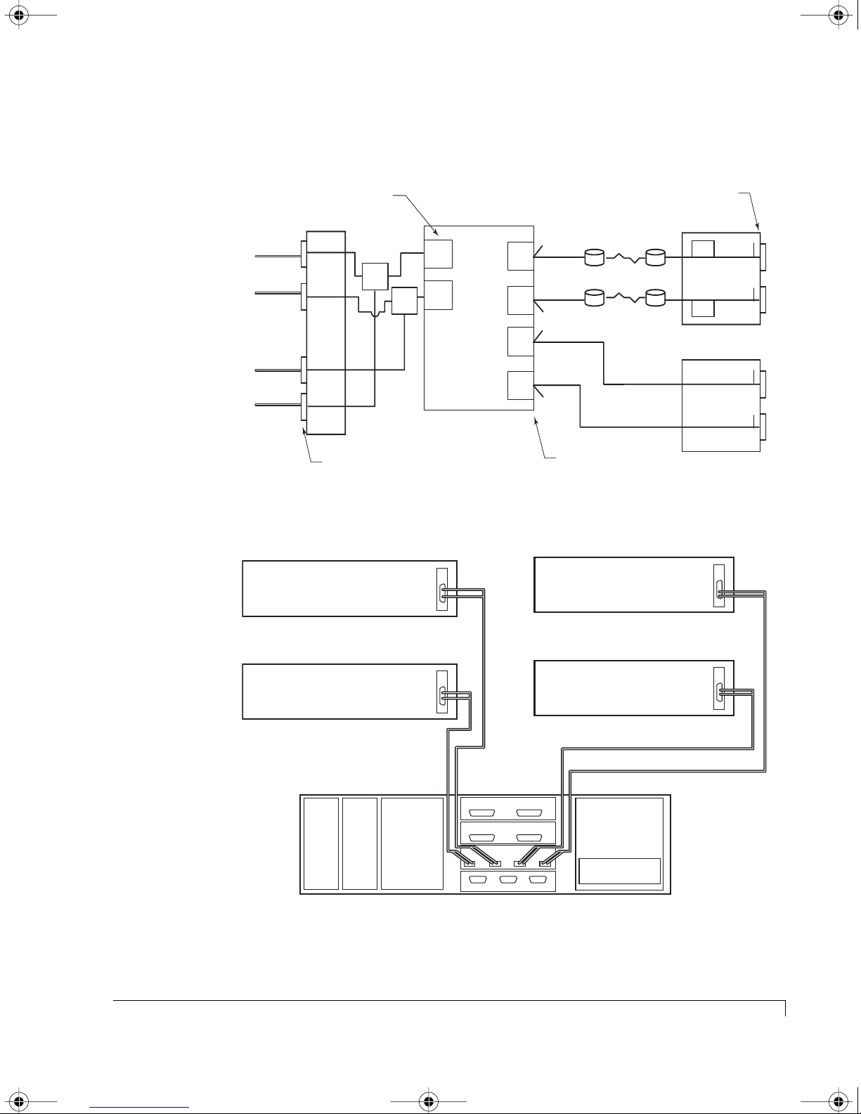
4100FS.book Page 61 Tuesday, July 8, 2003 4:35 PM
Setup for a Multiple Hosts - Single HBAs (Hubs Enabled)
Connect the Fibre Channel data cables as described in the following diagrams.
Chapter 3 - Setup and Installation
Host System #3
HBA 1
Host System #4
HBA 1
Host System #2
HBA 1
Host System #1
HBA 1
Controller FC Host Ports
P1
P2
HOST I/O
HUB
HUB
FC1
FC2
Active
Active
RAID Controller
Disk
CH1
Disk
CH2
Disk
CH0
T
T
T
P4
Disk
P3
Controller 1 (A)
CH3
T
T= Location of internal termination
Host I/O Connectors
Controller Disk Ports
Logical Diagram - Multiple Host with Single HBAs (Hubs Enabled)
FC HBA 1
Host Computer #4
Host Computer #1
Drives 7 - 12
Drives 1 - 6
Drive I/O Connectors
SEP
SEP
SAF-TE Disk I/O
Host SCSI I/O
FC HBA 1
T
CH 1 CH 2
T
T
CH 0 CH 3
T
Fibre Channel Data Cable
Fibre Channel Data Cable
Host Computer #3
Fibre Channel Data Cable
Power
Power
Supply
Supply
Fibre Channel Data Cable
Connect to P2
FC HBA 1
Connect to P1
Cooling
Fans
SAFTE Disk I/O
Chl 1 Chl 2
SCSI Disk I/O
Chl 0 Chl 3
Host I/O
Ctlr 1 Ctlr 2SAF-TE
Host Computer #2
P4 P3P2P1
RAID Controller
NexStor 4110FS
Host Cabling Diagram - Multiple Host with Single HBAs (Hubs Enabled)
Stand-Alone Dual Port:Host Cabling
Connect to P4
FC HBA 1
Connect to P3
61
Page 74
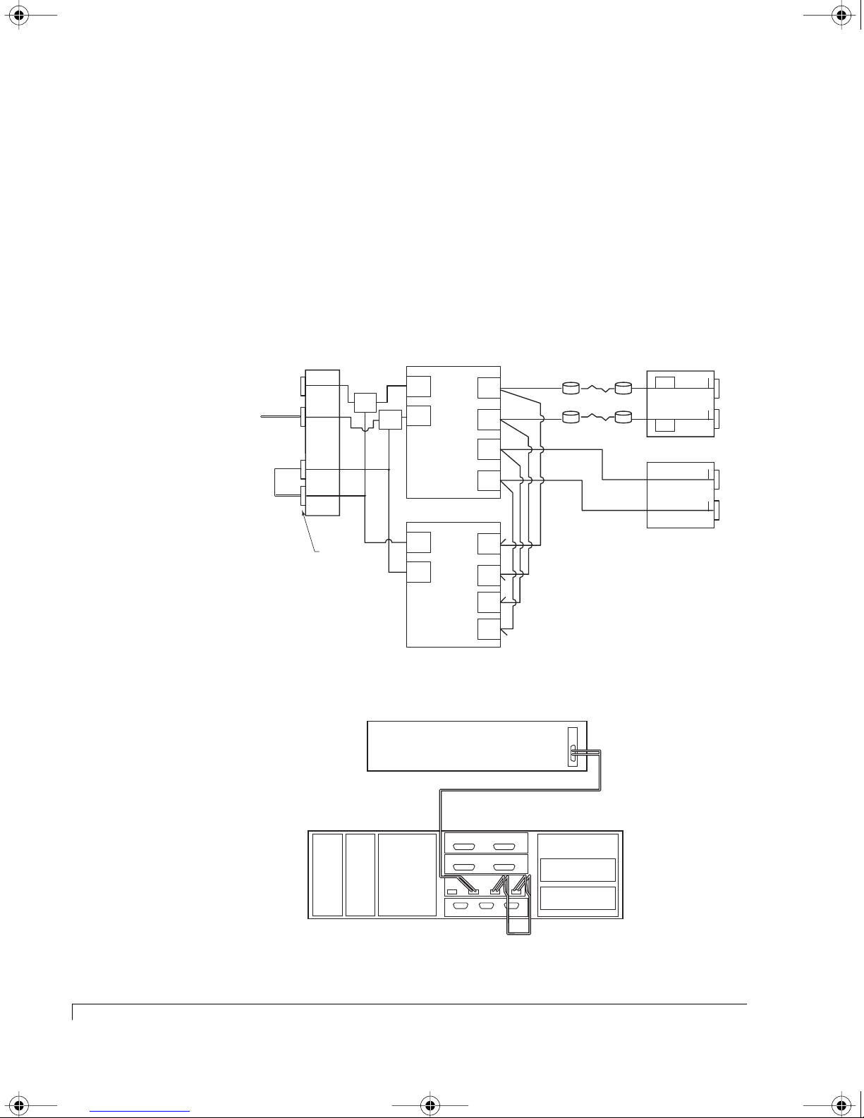
4100FS.book Page 62 Tuesday, July 8, 2003 4:35 PM
Chapter 3 - Setup and Installation
Active-Active Single Port:Host Cabling
This topology is chosen when the desired application requires a high-performance
robust full system level fault-tolerant disk storage solution and transparent
controller failover/failback.
with a single port HBA and is ideal when the host driver software will not
support LUNs that appear twice.
Setup for Single Host - Single HBA (Hubs Enabled)
Connect the Fibre Channel data cables as described in the following diagrams.
This dual controller configuration supports a host
Host System #1 HBA #1
P1
P2
P4
P3
Jumper Cable
HOST I/O
Host I/O
Connectors
HUB
HUB
FC1
FC2
Controller 1 (A)
FC2
FC1
Controller 2 (B)
RAID Controller
Active
Passive
RAID Controller
Active
Passive
Disk
CH1
Disk
CH2
Disk
CH0
Disk
CH3
Disk
CH1
Disk
CH2
Disk
CH0
Disk
CH3
Drives 7 - 12
Drives 1 - 6
T
T
T
T= Location of internal termination
T
Logical Diagram - Single Host with Single HBA (Hubs Enabled)
FC HBA 1
Host Computer
SEP
SEP
SAF-TE Disk I/O
Host SCSI I/O
T
CH 1 CH 2
T
T
CH 0 CH 3
T
Host Cabling Diagram - Single Host with Single HBA (Hubs Enabled)
62
Active-Active Single Port:Host Cabling
Power
Supply
Power
Supply
Cooling
Fans
Fibre Channel Data Cable
Connect to P2
SAFTE Disk I/O
Chl 1
I/O
Chl 0 Chl 3
Host I/O
P4 P3P2P1
Ctlr 1 Ctlr 2SAF-TE
NexStor 4120FS
Chl 2
RAID Controller
RAID Controller
Fibre Channel Jumper Cable
Page 75
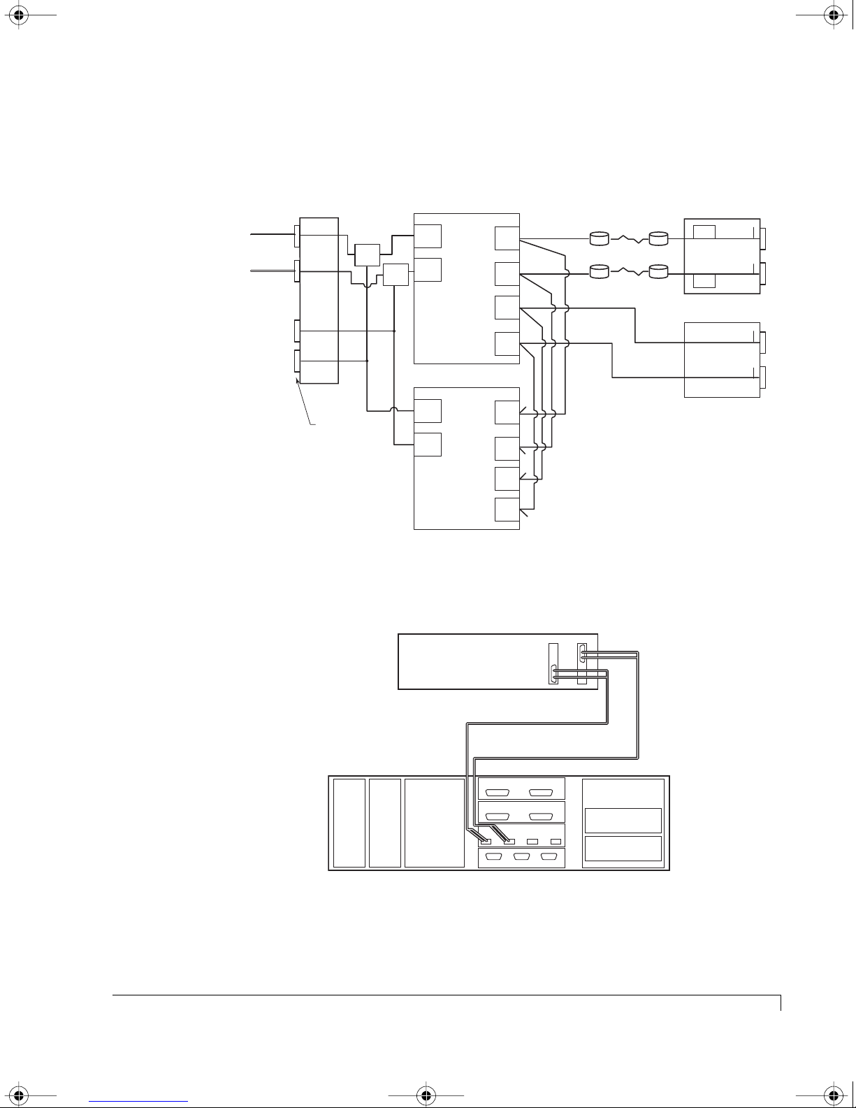
4100FS.book Page 63 Tuesday, July 8, 2003 4:35 PM
Setup for Single Host - Dual HBAs (Hubs Enabled)
Connect the Fibre Channel data cables as described in the following diagrams.
Chapter 3 - Setup and Installation
Host System #1 HBA #2
Host System #1 HBA #1
HOST I/O
P1
Host I/O
Connectors
HUB
HUB
P2
P4
P3
RAID Controller
FC1
Active
Passive
FC2
Controller 1 (A)
RAID Controller
Active
FC2
FC1
Passive
Controller 2 (B)
Disk
CH1
Disk
CH2
Disk
CH0
Disk
CH3
Disk
CH1
Disk
CH2
Disk
CH0
Disk
CH3
Drives 7 - 12
Drives 1 - 6
SEP
SEP
T
CH 1 CH 2
T
SAF-TE Disk I/O
T
CH 0 CH 3
T
T
T
T
T= Location of internal termination
T
Host SCSI I/O
Logical Diagram - Single Host with Dual HBAs (Hubs Enabled)
FC HBA 1 FC HBA 2
Host Computer #1
Fibre Channel Data Cable
Connect to P1
Fibre Channel Data Cable
Connect to P2
SAFTE Disk I/O
Power
Supply
Power
Supply
Cooling
Fans
Chl 1 Chl 2
I/O
Chl 0 Chl 3
Host I/O
Ctlr 1 Ctlr 2SAF-TE
RAID Controller
P3P2P1
P4
RAID Controller
NexStor 4120FS
Host Cabling Diagram - Single Host with Dual HBAs (Hubs Enabled)
Active-Active Single Port:Host Cabling
63
Page 76
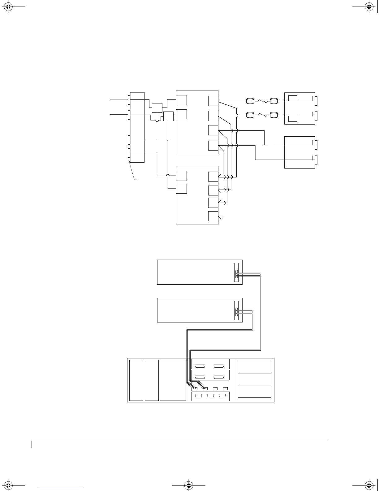
4100FS.book Page 64 Tuesday, July 8, 2003 4:35 PM
Chapter 3 - Setup and Installation
Setup for Dual Host - Single HBAs (Hubs Enabled)
Connect the Fibre Channel data cables as described in the following diagrams.
Host System #1 HBA #1
Host System #2 HBA #1
HOST I/O
P1
Host I/O
Connectors
HUB
HUB
P2
P4
P3
RAID Controller
FC1
Active
Passive
FC2
Controller 1 (A)
RAID Controller
Active
FC2
Passive
FC1
Controller 2 (B)
Disk
CH1
Disk
CH2
Disk
CH0
Disk
CH3
Disk
CH1
Disk
CH2
Disk
CH0
Disk
CH3
Drives 7 - 12
Drives 1 - 6
T
T
T
T= Location of internal termination
T
Logical Diagram - Dual Host with Single HBAs (Hubs Enabled)
FC HBA 1
SEP
SEP
SAF-TE Disk I/O
Host SCSI I/O
T
CH 1 CH 2
T
T
CH 0 CH 3
T
64
Active-Active Single Port:Host Cabling
Host Computer #2
FC HBA 1
Host Computer #1
Fibre Channel Data Cable
Power
Supply
Power
Supply
Connect to P1
Cooling
Fans
SAFTE Disk I/O
Chl 1 Chl 2
Chl 0 Chl 3
Host I/O
Ctlr 1 Ctlr 2SAF-TE
I/O
P4
Fibre Channel Data Cable
Connect to P2
RAID Controller
P3P2P1
RAID Controller
NexStor 4120FS
Host Cabling Diagram - Dual Host with Single HBAs (Hubs Enabled)
Page 77
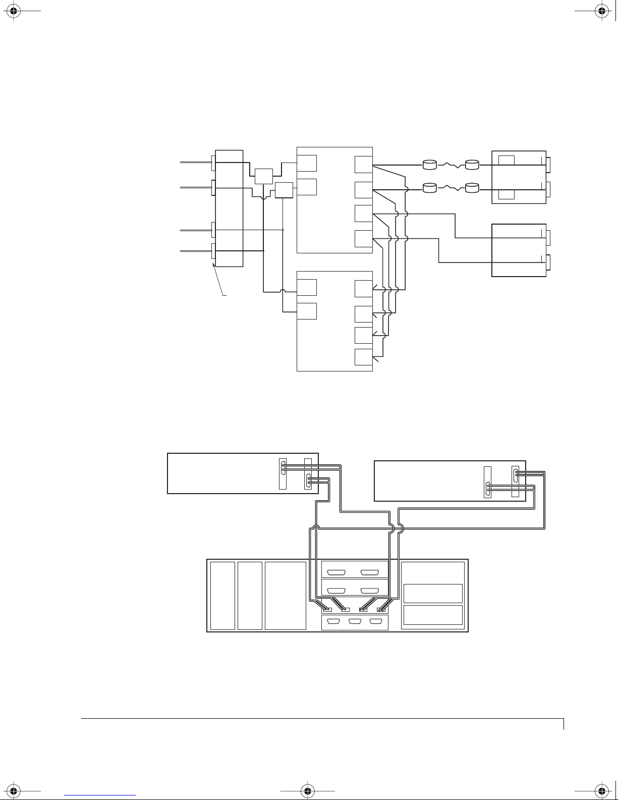
4100FS.book Page 65 Tuesday, July 8, 2003 4:35 PM
Setup for Dual Host - Dual HBAs (Quad Cabling - Hubs Enabled)
Connect the Fibre Channel data cables as described in the following diagrams.
Chapter 3 - Setup and Installation
Host System #1 HBA #2
Host System #2 HBA #1
Host System #2 HBA #2
Host System #1 HBA #1
HOST I/O
P1
Host I/O
Connectors
HUB
HUB
P2
P4
P3
RAID Controller
FC1
Active
Passive
FC2
Controller 1 (A)
RAID Controller
Active
FC2
FC1
Passive
Controller 2 (B)
Disk
CH1
Disk
CH2
Disk
CH0
Disk
CH3
Disk
CH1
Disk
CH2
Disk
CH0
Disk
CH3
Drives 7 - 12
Drives 1 - 6
T
T
T
T= Location of internal termination
T
Logical Diagram - Dual Host with Dual HBAs (Quad Cabling - Hubs Enabled)
SEP
SEP
SAF-TE Disk I/O
Host SCSI I/O
T
CH 1 CH 2
T
T
CH 0 CH 3
T
Host Computer #2
Power
Power
Supply
Supply
FC HBA 1FC HBA 2
Fibre Channel Data Cable
Connect to P2
Cooling
Fans
Fibre Channel Data Cable
Connect to P4
SAFTE Disk I/O
Chl 1 Chl 2
I/O
Chl 0 Chl 3
Host I/O
P4 P3P2P1
Ctlr 1 Ctlr 2SAF-TE
Host Computer #1
RAID Controller
RAID Controller
FC HBA 1
FC HBA 2
Fibre Channel Data Cable
Connect to P3
Fibre Channel Data Cable
Connect to P1
NexStor 4120FS
Host Cabling Diagram - Dual Host with Dual HBAs (Quad Cabling - Hubs Enabled)
Active-Active Single Port:Host Cabling
65
Page 78
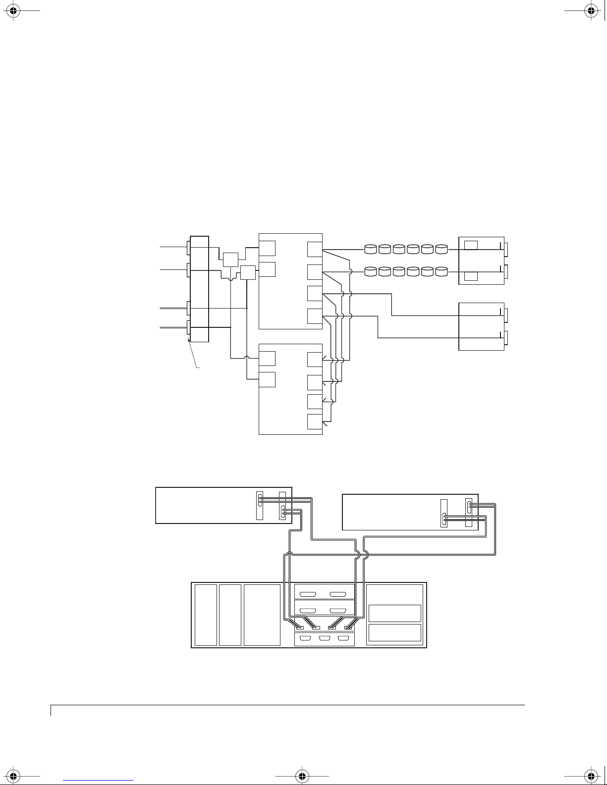
4100FS.book Page 66 Tuesday, July 8, 2003 4:35 PM
Chapter 3 - Setup and Installation
Active-Active Dual Port:Host Cabling
This topology is chosen when the desired application requires a high-performance
robust full system level fault-tolerant disk storage solution.
configuration supports multiple hosts, and failover and failback operations. All
LUNs are available to all hosts.
Setup for Dual Host - Dual HBAs (Hubs Enabled)
Connect the Fibre Channel data cables as described in the following diagrams.
This dual controller
Host System #1 HBA #2
Host System #2 HBA #1
Host System #2 HBA #2
Host System #1 HBA #1
HOST I/O
P1
P2
P4
P3
Host I/O
Connectors
Logical Diagram - Dual Host with Dual HBAs (Hubs Enabled)
Host Computer #2
HUB
HUB
RAID Controller
FC1
Active
Active
FC2
Controller 1 (A)
RAID Controller
Active
FC2
FC1
Active
Controller 2 (B)
FC HBA 1FC HBA 2
Disk
CH1
Disk
CH2
Disk
CH0
Disk
CH3
Disk
CH1
Disk
CH2
Disk
CH0
Disk
CH3
T
T
T
T= Location of internal termination
T
Drives 7 - 12
Drives 1 - 6
Host Computer #1
FC HBA 1
SEP
SEP
SAF-TE Disk I/O
Host SCSI I/O
FC HBA 2
T
CH 1 CH 2
T
T
CH 0 CH 3
T
Power
Supply
Host Cabling Diagram - Dual Host with Dual HBAs (Hubs Enabled)
66
Active-Active Dual Port:Host Cabling
Fibre Channel Data Cable
Power
Supply
Connect to P2
Cooling
Fans
Fibre Channel Data Cable
Connect to P4
SAFTE Disk I/O
Chl 1 Chl 2
I/O
Chl 0 Chl 3
Host I/O
P4 P3P2P1
Ctlr 1 Ctlr 2SAF-TE
NexStor 4120FS
RAID Controller
RAID Controller
Fibre Channel Data Cable
Connect to P3
Fibre Channel Data Cable
Connect to P1
Page 79
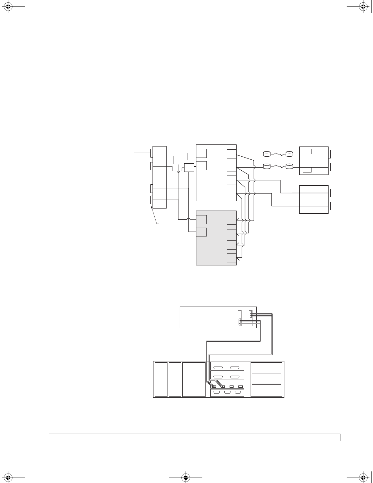
4100FS.book Page 67 Tuesday, July 8, 2003 4:35 PM
Active-Passive Dual Port:Host Cabling
This topology is chosen when the desired application requires a high-availability
high access fault-tolerant disk storage solution. This dual controller configuration
supports multiple hosts and failover and failback operations. All LUNs are available
to all hosts. The dual host configuration is ideal for shared storage clustering.
Setup for Single Host - Dual HBAs (Hubs Enabled)
Connect the Fibre Channel data cables as described in the following diagrams.
Chapter 3 - Setup and Installation
Host System #1 HBA #1
Host System #1 HBA #2
HOST I/O
P1
Host I/O
Connectors
HUB
HUB
P2
P4
P3
RAID Controller
FC1
Active
FC2
Active
Controller 1 (A)
RAID Controller
Passive
FC2
FC1
Passive
Controller 2 (B)
Passive
Disk
CH1
Disk
CH2
Disk
CH0
Disk
CH3
Disk
CH1
Disk
CH2
Disk
CH0
Disk
CH3
Drives 7 - 12
Drives 1 - 6
T
T
T
T= Location of internal termination
T
Logical Diagram - Single Host with Dual HBAs (Hubs Enabled)
FC HBA 1FC HBA 2
SEP
SEP
SAF-TE Disk I/O
Host SCSI I/O
T
CH 1 CH 2
T
T
CH 0 CH 3
T
Host Computer #1
Fibre Channel Data Cable
Connect to P1
Fibre Channel Data Cable
Connect to P2
SAFTE Disk I/O
Power
Supply
Power
Supply
Cooling
Fans
Chl 1 Chl 2
Chl 0 Chl 3
Host I/O
Ctlr 1 Ctlr 2SAF-TE
I/O
P4
RAID Controller
P3P2P1
RAID Controller
NexStor 4120FS
Host Cabling Diagram - Single Host with Dual HBAs (Hubs Enabled)
Active-Passive Dual Port:Host Cabling
67
Page 80
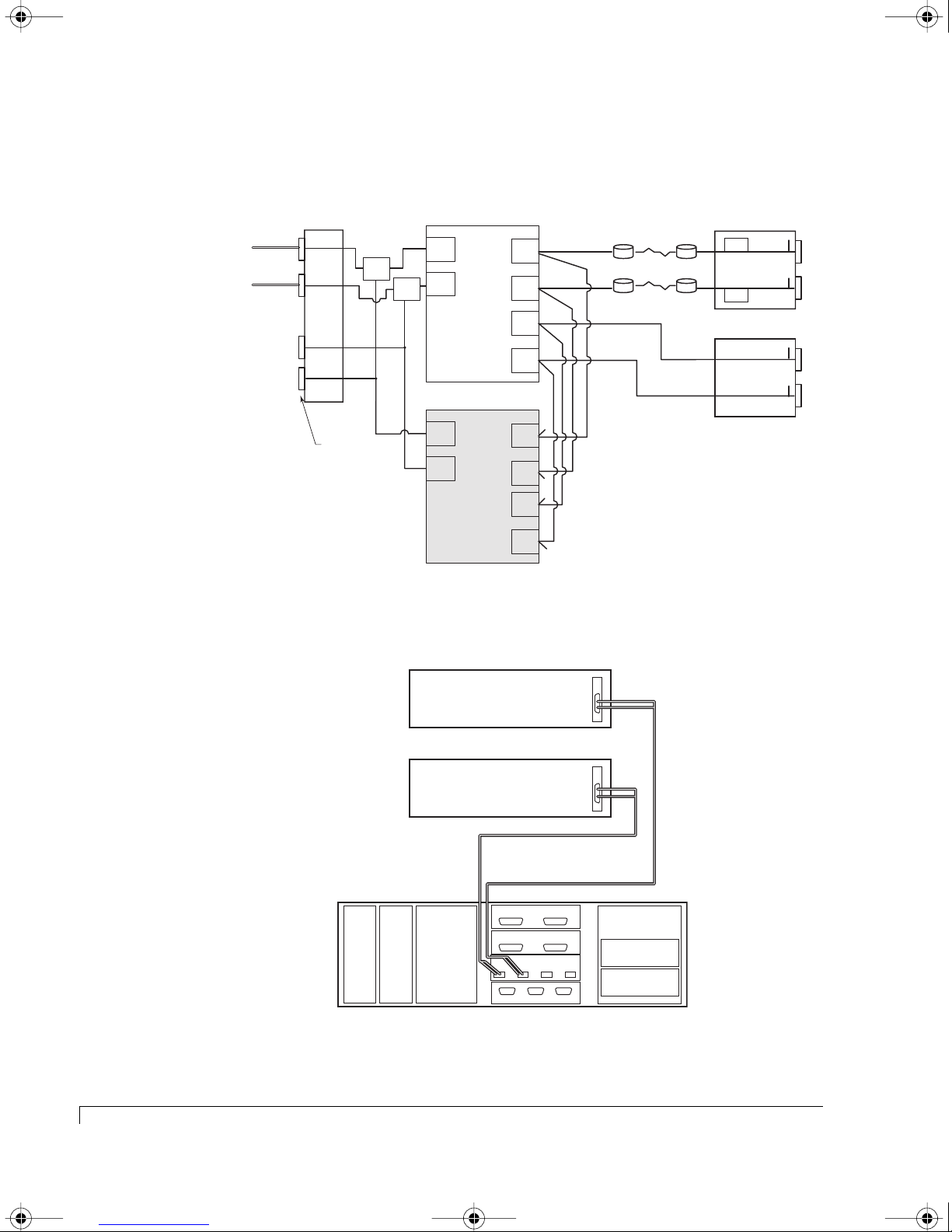
4100FS.book Page 68 Tuesday, July 8, 2003 4:35 PM
Chapter 3 - Setup and Installation
Setup for Dual Host - Single HBAs (Hubs Enabled)
Connect the Fibre Channel data cables as described in the following diagrams.
Host System #1 HBA #1
Host System #2 HBA #1
HOST I/O
P1
Host I/O
Connectors
HUB
HUB
P2
P4
P3
RAID Controller
FC1
Active
FC2
Active
Controller 1 (A)
RAID Controller
Passive
FC2
FC1
Passive
Controller 2 (B)
Disk
CH1
Disk
CH2
Disk
CH0
Disk
CH3
Disk
CH1
Disk
CH2
Disk
CH0
Disk
CH3
T
T
T
T= Location of internal termination
T
Passive
Logical Diagram - Dual Host with Single HBAs (Hubs Enabled)
FC HBA 1
Drives 7 - 12
Drives 1 - 6
SEP
SEP
SAF-TE Disk I/O
Host SCSI I/O
T
CH 1 CH 2
T
T
CH 0 CH 3
T
68
Active-Passive Dual Port:Host Cabling
Host Computer #2
FC HBA 1
Host Computer #1
Fibre Channel Data Cable
Power
Supply
Power
Supply
Connect to P1
Cooling
Fans
SAFTE Disk I/O
Chl 1 Chl 2
Chl 0 Chl 3
Host I/O
Ctlr 1 Ctlr 2SAF-TE
I/O
P4
Fibre Channel Data Cable
Connect to P2
RAID Controller
P3P2P1
RAID Controller
NexStor 4120FS
Host Cabling Diagram - Dual Host with Single HBAs (Hubs Enabled)
Page 81

4100FS.book Page 69 Tuesday, July 8, 2003 4:35 PM
Upgrades
At some point you may have a need to upgrade your storage system to increase
the storage capacities and/or the RAID capabilities. The NexStor 4100FS Series
Storage System provides you with this ability to meet your expanding data
storage requirements.
The RAID controllers support a feature know as “drive roaming,” where the
controllers can keep track of which drive belong to which logical arrays. In the
event the drives’ enclosure is changed or they are moved to another enclosure
attached to the same set of controllers, the arrays will not be lost or damaged.
The upgrade process is relatively easy, you simply refer to the new Enclosure
Configuration Cabling section to find the new configuration that supports the
number of enclosures/drives you will be adding. Set the enclosure SAF-TE Disk I/O
card(s) switch settings for the new configuration and cabling the storage system
enclosures as indicated. Then, if applicable, refer to the Topology Host Cabling
section to locate the new topology and re-cable your new configuration as
indicated.
Chapter 3 - Setup and Installation
NOTE: Changing operating mode topologies may have an effect on which
configuration you may use. Refer to the Enclosure Configuration Cabling
section and the Topology Host Cabling section to ensure that you have
selected a configurations that is supported. Refer to “Operating Modes
Overview” on page 19 for more information.
NOTE: You will not be required to move disk drives around in the enclosure(s),
the Drive Roaming feature will locate those drives when the entire
system is powered back up.
Upgrades
69
Page 82

4100FS.book Page 70 Tuesday, July 8, 2003 4:35 PM
Chapter 3 - Setup and Installation
Powering On the Storage System
After you have the system setup and installed, you are ready to power on the
storage system enclosure(s).
NOTE: Ensure that none of the data cables or power cables are obstructing the
air flow exiting the cooling fan module.
1 Locate the power supply On/Off switches at the rear of the NexStor 4100FS
Series Storage System enclosure(s).
2 Press each power supply switch to its “On” position. (Repeat this step for
each of the attached storage system enclosure(s).)
All enclosures will perform a power on self test during their initial start.
3 Next power on the host computer(s) which is connected to the storage
system.
Powering Off the Storage System
NOTE: If you are planning to completely shut down the entire system, power
down the host system first.
1 If applicable, ensure that the controller(s) have been gracefully shut down.
Refer to “Shutdown Both” in the VT-100 or AdminiStor software guides.
2 Press each enclosure’s power supply On/Off switches to their “Off” position.
3 Repeat the above step for each of the attached storage system enclosure(s).
70
Powering On the Storage System
Page 83

4100FS.book Page 71 Tuesday, July 8, 2003 4:35 PM
Chapter 4
SAN Solution Strategies
This chapter will describe connecting the NexStor 4120FS Series Storage Systems
providing an Active-Active/Active-Passive solution to a Storage Area Network
(SAN).
Active-Active:Dual Port Mode for SAN
At the heart of this strategy is the Active-Active Dual Port operating mode. In this
mode, four Fibre Channel (FC) ports are simultaneously active when both
controllers are online. In the event of a controller failure, two FC ports remain
available to service all host I/O. The table below illustrates how LUNs are
presented by each controller in this mode.
Controller 1
Host Port 0 (FC1)
Both Controllers Online Controller 1
LUNs
Controller 1 Failed Inactive Inactive Controller 2
Controller 2 Failed Controller 1
LUNs
Note that when a controller fails, the surviving controller continues to present its
LUNs to its Host Port 0, and changes to present the failed controller’s LUNs to its
Host Port 1. The Fibre Channel Node and Port World Wide Names corresponding
to the failed controller’s Host Port 0 (FC1) are also associated with its LUNs on
the surviving controller’s Host Port 1 (FC2).
Controller 1
Host Port 1 (FC2)
Controller 1
LUNs
Controller 2
LUNs
Controller 2
Host Port 0 (FC1)
Controller 2
LUNs
LUNs
Inactive Inactive
Host Port 1 (FC2)
Controller 2
Controller 2
LUNs
Controller 1
LUNs
71
Page 84
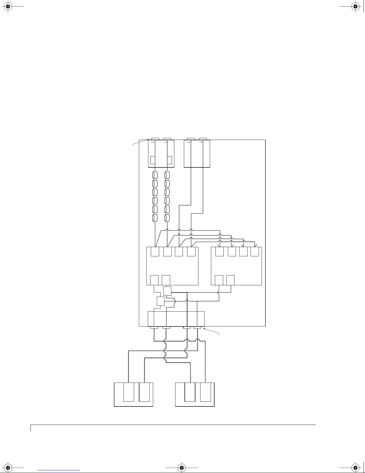
4100FS.book Page 72 Tuesday, July 8, 2003 4:35 PM
Chapter 4 - SAN Solution Strategies
Hubs Enabled
In the following illustrations, the controllers are configured in an Active-Active Dual
Port mode with the internal hubs enabled.
In the example below, two hosts are connected via two independent loops using
the enclosure’s built-in hub bypass circuits. These circuits provide two internal
hubs, eliminating the need for the use of external Fibre Channel hardware, other
than the cables.
Disk I/O
Connectors
NexStor 4120FS
JFS RAID Controller
CH 1 CH 2
T
SEP
Drives 7 - 12
Disk
CH1
LUN 1
Active
FC1
T
Disk
LUN 1
FC2
HUB
SEP
SAF-TE Disk I/O Card
Drives 1 - 6
Disk
CH2
Active
HUB
CH0
CH 0 CH 3
T
Disk
CH3
Controller 1 (A)
T
I/O Card
T
Disk
CH1
Active
LUN 2
JFS RAID Controller
FC2
Disk
LUN 2
FC1
T
CH2
Active
T
Disk
CH0
T= Location of internal termination
T
Disk
CH3
Controller 2 (B)
Host 1
72
Active-Active:Dual Port Mode for SAN
See's LUN 1 & LUN 2
See's LUN 1 & LUN 2
FC HBA
FC HBA
HOST I/O
P2
P1
P4
See's LUN 1 & LUN 2
Host 2
P3
FC HBA
Host I/O
See's LUN 1 & LUN 2
FC HBA
Connectors
Page 85
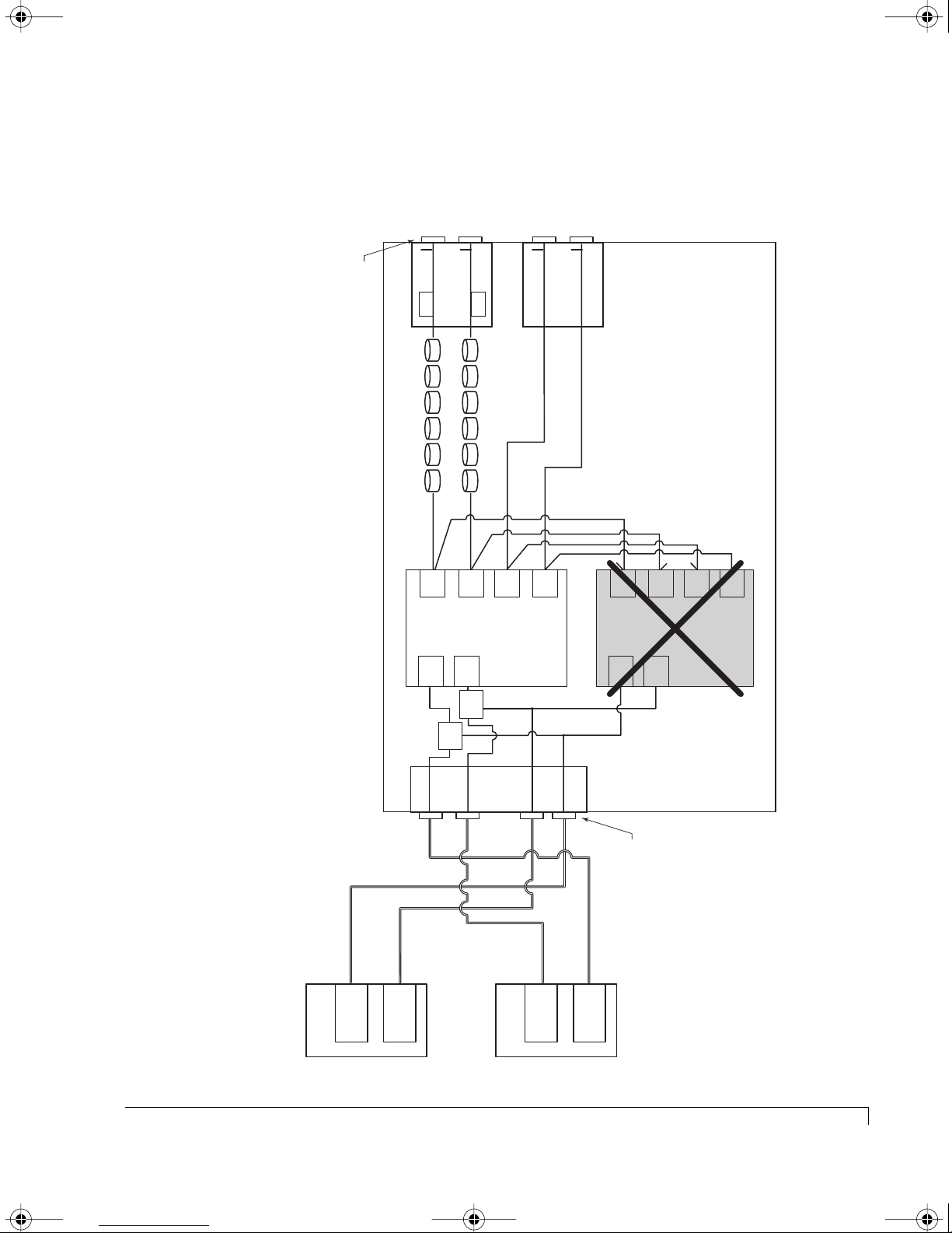
4100FS.book Page 73 Tuesday, July 8, 2003 4:35 PM
This example illustrates the conditions when Controller 2 fails. Note that both
hosts can still see Controller 1’s LUNs (LUN 1) and Controller 2’s LUNS (LUN 2).
However, each host HBA can only see one LUN, instead of both.
Chapter 4 - SAN Solution Strategies
Disk I/O
Connectors
NexStor 4120FS
JFS RAID Controller
CH 1 CH 2
T
SEP
Drives 7 - 12
Disk
CH1
LUN 1
Active
FC1
T
Disk
LUN 2
FC2
SEP
CH2
Active
CH 0 CH 3
T
SAF-TE Disk I/O Card
Drives 1 - 6
Disk
Disk
CH0
T
CH3
Controller 1
I/O Card
T
Disk
CH1
Active
LUN 2
JFS RAID Controller
FC2
Disk
LUN 2
FC1
T= Location of internal termination
T
T
Disk
CH2
CH0
Active
Disk
CH3
T
FAILED
Controller 2
See's LUN 1 & LUN 2
Host 1
FC HBA
HOST I/O
P1
See's LUN 1 & LUN 2
FC HBA
HUB
HUB
P2
Host 2
P3
P4
See's LUN 1 & LUN 2
FC HBA
Host I/O
Connectors
See's LUN 1 & LUN 2
FC HBA
Active-Active:Dual Port Mode for SAN
73
Page 86
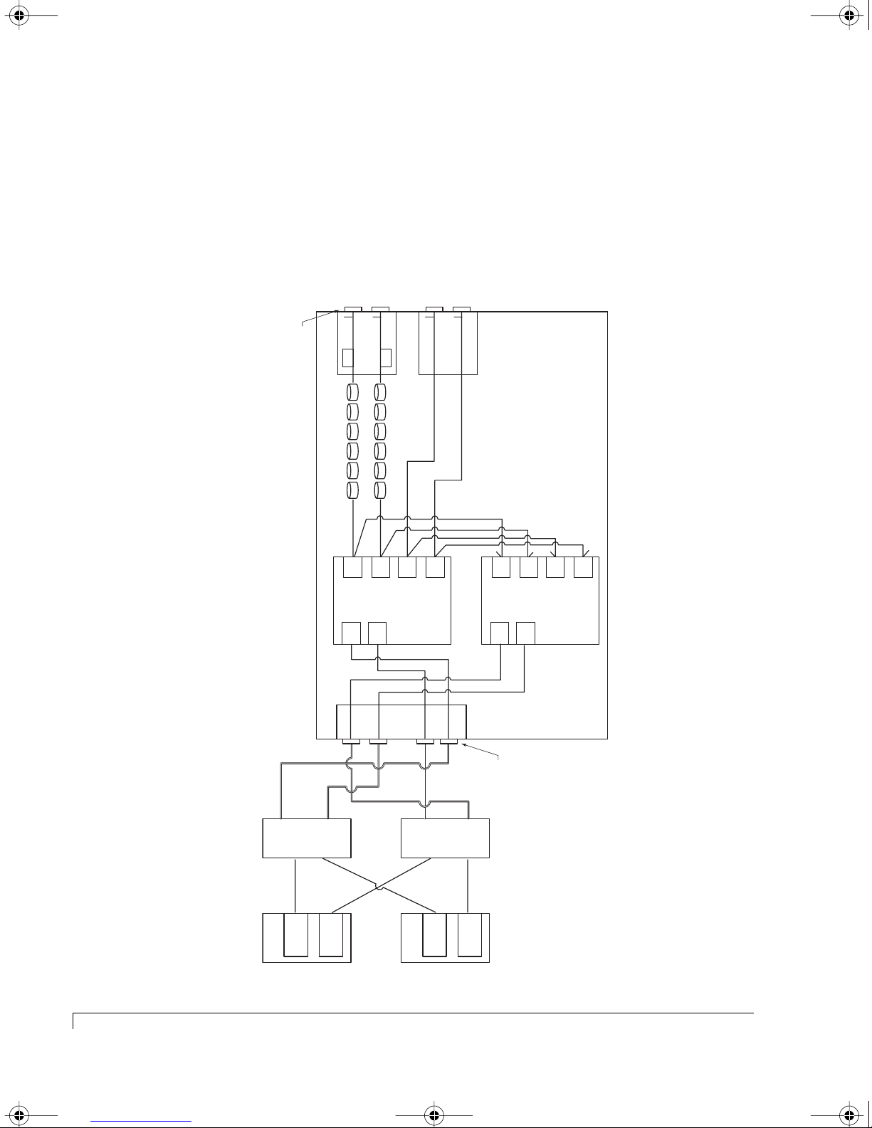
4100FS.book Page 74 Tuesday, July 8, 2003 4:35 PM
Chapter 4 - SAN Solution Strategies
Hubs Disabled
In the following illustrations, the two controllers are configured in an Active-Active
Dual Port mode with the internal hubs disabled.
In the example below, two hosts are connected via two independent switches.
Using external switches supports higher bandwidth, since the host ports are not
required to share bandwidth on a loop.
Disk I/O
Connectors
NexStor 4120FS
CH 1 CH 2
T
SEP
Drives 7 - 12
Disk
CH1
LUN 1
Active
JFS RAID Controller
FC1
T
Disk
LUN 1
FC2
CH2
Active
SEP
SAF-TE Disk I/O
Drives 1 - 6
Disk
T
CH0
CH 0 CH 3
T
Disk
CH3
Controller 1 (A)
Disk I/O
T
Disk
CH1
Active
LUN 2
JFS RAID Controller
FC2
T= Location of internal termination
T
T
Disk
Disk
CH2
CH0
Active
LUN 2
FC1
T
Disk
CH3
Controller 2 (B)
See's LUN 1 &
LUN 2
Host 1
74
Active-Active:Dual Port Mode for SAN
Switch 1
FC HBA
HOST I/O
P1
See's LUN 1 &
LUN 2
FC HBA
P2
P3
P4
Host I/O
Connectors
Switch 2
See's LUN 1 &
LUN 2
LUN 2
FC HBA
Host 2
See's LUN 1 &
FC HBA
Page 87
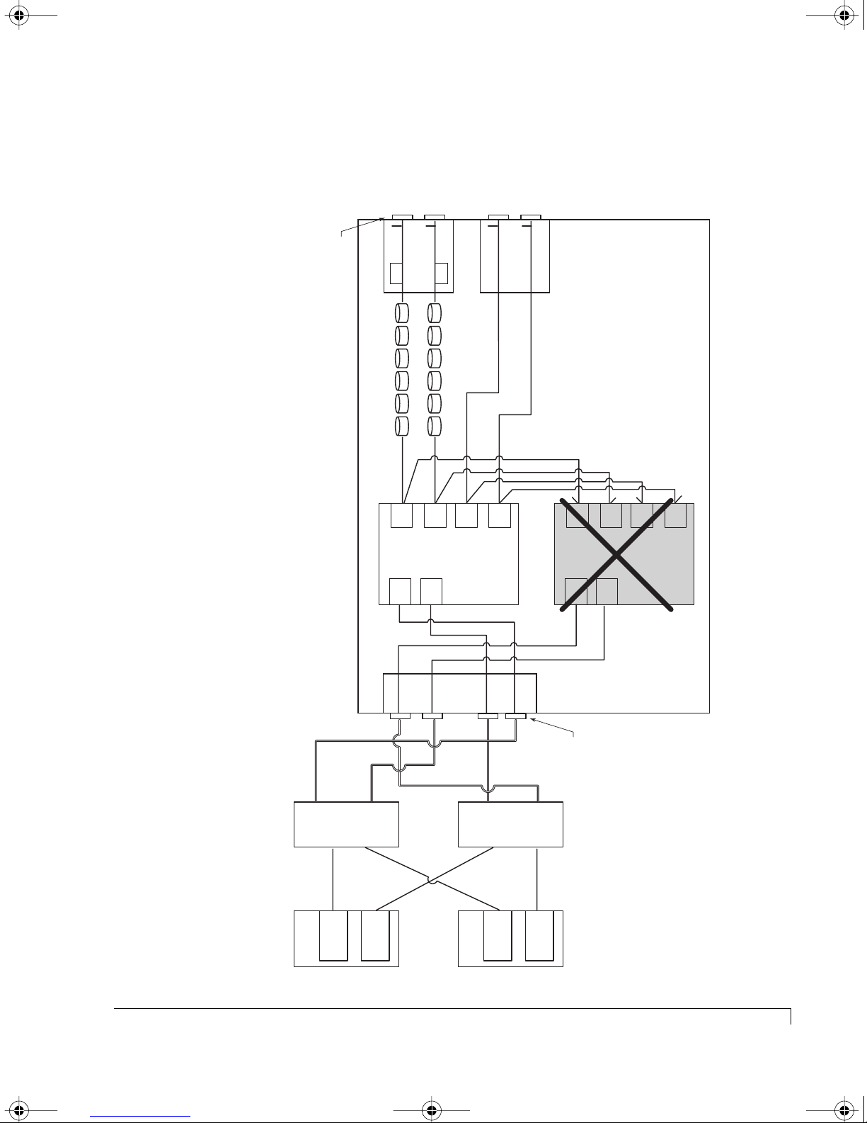
4100FS.book Page 75 Tuesday, July 8, 2003 4:35 PM
In this example, two hosts are connected via two independent switches. Note
that both hosts can still see Controller 1’s LUNs (LUN 1) and Controller 2’s LUNs
(LUN 2). However, each host HBA can only see one LUN, instead of both.
Chapter 4 - SAN Solution Strategies
Disk I/O
Connectors
NexStor 4120FS
JFS RAID Controller
CH 1 CH 2
T
SEP
Drives 7 - 12
Disk
CH1
LUN 1
Active
FC1
T
LUN 2
Disk
FC2
SEP
CH2
Active
SAF-TE Disk I/O
Drives 1 - 6
Disk
CH0
CH 0 CH 3
T
Disk
CH3
Controller 1 (A)
T
Disk I/O
T
Disk
CH1
In-Active
LUN 2
JFS RAID Controller
FC2
Disk
LUN 2
FC1
T= Location of internal termination
T
T
Disk
CH2
CH0
In-Active
T
Disk
CH3
Controller 2 (B)
FAILED
Host 1
See's LUN 1
FC HBA
Switch 1
HOST I/O
See's LUN 2
FC HBA
P2
P1
P3
P4
Host I/O
Connectors
Switch 2
See's LUN 2
FC HBA
Active-Active:Dual Port Mode for SAN
75
Host 2
See's LUN 1
FC HBA
Page 88
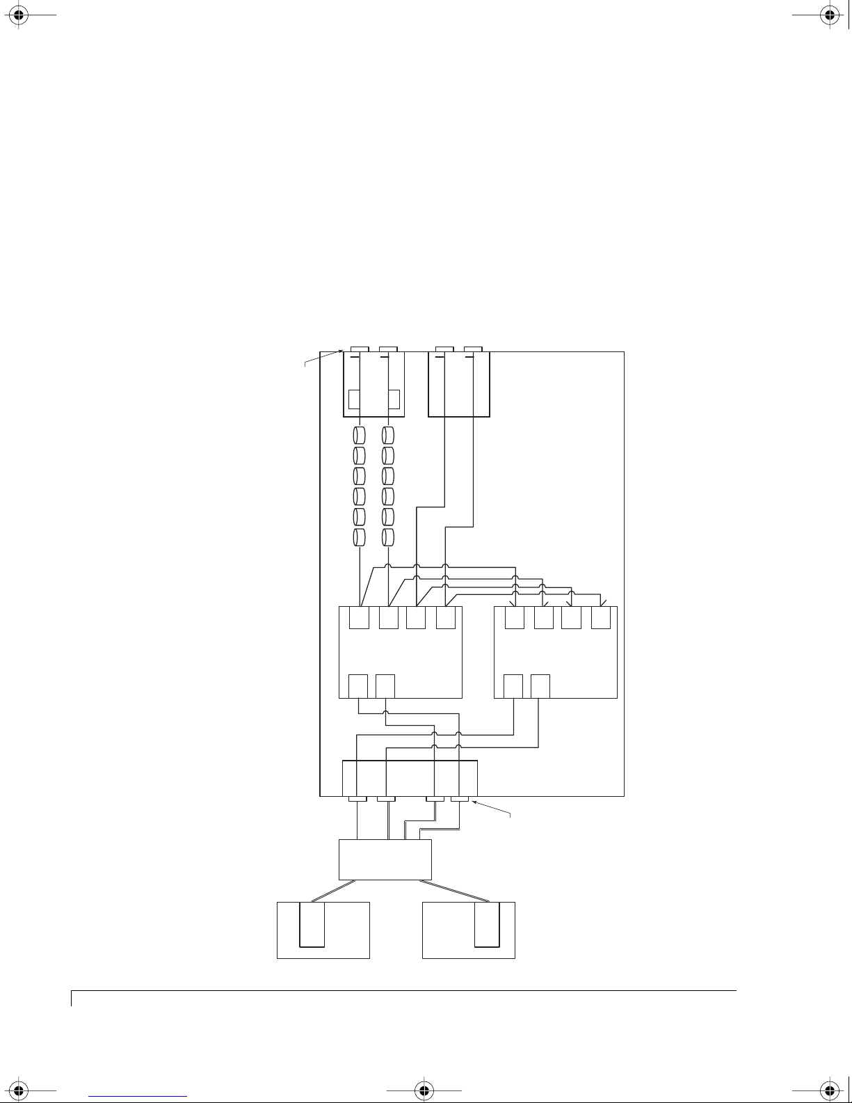
4100FS.book Page 76 Tuesday, July 8, 2003 4:35 PM
Chapter 4 - SAN Solution Strategies
Active-Active:Single Port Mode for SAN
There are several scenarios where it may be desirable to configure the controllers
in Active-Active Single Port mode. In general, these are situations where the hosts
have a single Fibre Channel port, and so the SAN is not truly fault-tolerant.
Hubs Disabled (Single Port Hosts and One Switch)
The following illustration depicts two single ported hosts connected to the two
controllers via a single switch.
Disk I/O
Connectors
NexStor 4120FS
JFS RAID Controller
CH 1 CH 2
T
SEP
Drives 7 - 12
Disk
CH1
LUN 1
Active
FC1
T
Disk
LUN 1
FC2
SEP
Drives 1 - 6
CH2
Passive
CH 0 CH 3
T
SAF-TE Disk I/O
Disk
Disk
CH0
CH3
T
Controller 1 (A)
JFS RAID Controller
I/O Card
T
Disk
LUN 2
FC2
CH1
Passive
Disk
LUN 2
FC1
CH2
Active
T
T
Disk
T= Location of internal termination
T
Disk
CH0
CH3
Controller 2 (B)
76
Active-Active:Single Port Mode for SAN
Host 1
Host Link 1
FC HBA
HOST I/O
P2
P1
P3
P4
Host I/O
Connectors
Switch
Host Link 2
Host 2
FC HBA
Page 89

4100FS.book Page 77 Tuesday, July 8, 2003 4:35 PM
In this case, there would be an advantage to configuring the controllers in
Active-Active Dual Port mode, because of increased connectivity. However, the
host driver software would need to handle the fact that each LUN would appear
twice in the SAN fabric, and that one image of the LUNs would disappear if one
controller failed.
Depending on the host software being used, it may be more desirable to run in
Active-Active Single Port mode, since a controller failover would be transparent
to the hosts (as far as the number of LUN images and the port WWNs attached to
the LUNs). The advantages of using a switch is that the two hosts each have a
direct path to a controller port and don’t have to compete for access on the same
loop.
Chapter 4 - SAN Solution Strategies
Active-Active:Single Port Mode for SAN
77
Page 90
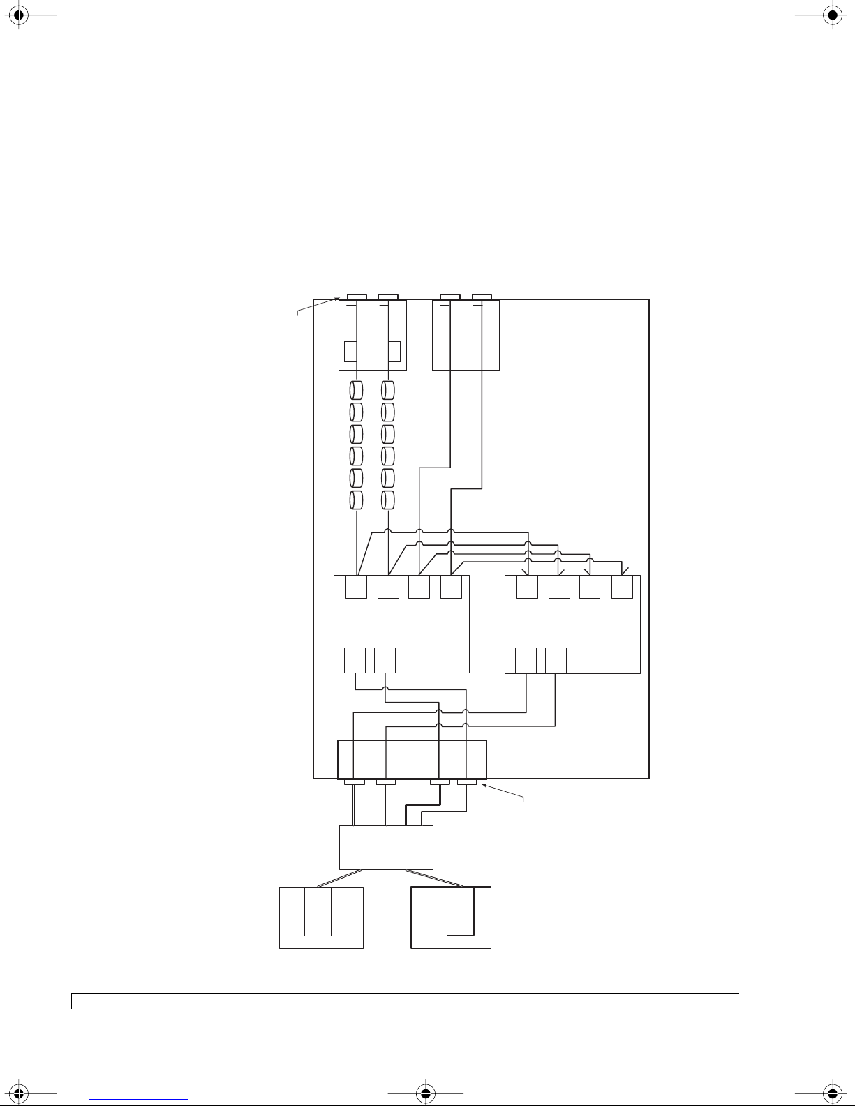
4100FS.book Page 78 Tuesday, July 8, 2003 4:35 PM
Chapter 4 - SAN Solution Strategies
Hubs Disabled (Single External Hub)
The following illustration depicts the hosts in a single loop configuration using an
external hub. When a controller failover occurs, this configuration operates much
the same as the previous one which uses a switch. The advantage is that a hub is
less expensive. In Active-Active Dual Port mode, you must manage the multiple
images of the same LUN.
Disk I/O
Connectors
NexStor 4120FS
JFS RAID Controller
CH 1 CH 2
T
SEP
Drives 7 - 12
Disk
CH1
LUN 1
Active
FC1
T
Disk
LUN 1
FC2
Passive
SEP
Drives 1 - 6
CH2
CH 0 CH 3
T
SAF-TE Disk I/O
Disk
Disk
CH0
CH3
T
Controller 1 (A)
JFS RAID Controller
I/O Card
T
Disk
LUN 2
FC2
CH1
Passive
Disk
LUN 2
FC1
T= Location of internal termination
T
T
Disk
CH2
CH0
Active
T
Disk
CH3
Controller 2 (B)
78
Active-Active:Single Port Mode for SAN
Host 1
Host Link 1
FC HBA
HOST I/O
P1
P2
Hub
Host 2
P3
P4
Host I/O
Connectors
Host Link 2
FC HBA
Page 91
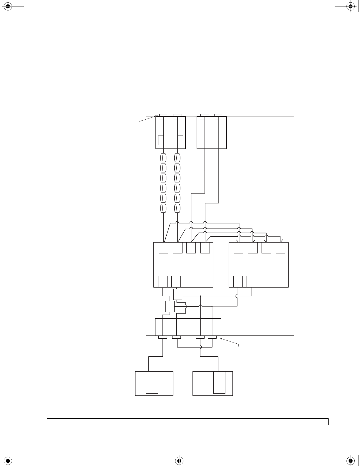
4100FS.book Page 79 Tuesday, July 8, 2003 4:35 PM
Hubs Enabled
The illustration below depicts hosts in a single loop configuration with the
internal hubs enabled. The internal hubs eliminate the need for an external hub.
It allows one or two hosts to be connected to the Active-Active storage enclosure
without the cost of external hardware other than cables.
Chapter 4 - SAN Solution Strategies
Disk I/O
Connectors
NexStor 4120FS
JFS RAID Controller
CH 1 CH 2
T
SEP
Drives 7 - 12
Disk
CH1
LUN 1
Active
FC1
T
Disk
LUN 1
FC2
CH2
Passive
SEP
SAF-TE Disk I/O
Drives 1 - 6
Disk
CH 0 CH 3
T
CH0
T
Disk
CH3
Controller 1 (A)
Disk I/O
T
Disk
CH1
LUN 2
Active
JFS RAID Controller
FC2
Disk
LUN 2
FC1
T= Location of internal termination
T
T
Disk
CH2
CH0
Passive
T
Disk
CH3
Controller 2 (B)
Host Link 1
Host 1
HOST I/O
FC HBA
HUB
HUB
P2
P1
Cable
Jumper
P4
Host 2
P3
Host I/O
Connectors
Host Link 2
FC HBA
Active-Active:Single Port Mode for SAN
79
Page 92

4100FS.book Page 80 Tuesday, July 8, 2003 4:35 PM
Chapter 4 - SAN Solution Strategies
SAN Configuration Not Supported
In the Active-Active:Dual Port configuration with two independent hubs or the
internal hubs, two single-ported hosts is not supported. The issue with this
configuration is that if a controller fails, each host loses access to one of the LUNs.
For example, if Controller 1 fails, Host 1 can no longer access LUN 2, because
Port 2 on Controller 2 has changed from presenting its own LUNs to presenting
Controller 1’s LUNs. A need for this SAN configuration can arise if multiple
single-ported hosts need access to LUNs from both controllers, and two hubs are
desired to improve performance by decreasing loop access contention.
Note that this SAN is only partially fault-tolerant because the hubs and controllers
have redundant hardware, but the hosts do not. The problem with this
configuration can be overcome by using a single switch at the cost of replacing
the two hubs with a switch. If loop access contention is not an issue, then the
single hub configuration works as well.
True LUN Sharing
When considering the presentation of LUNs for Active-Active controllers, a good
question is: “Why not just present all LUN on all ports?” The answer is that LUN
sharing greatly increases complexity and sacrifices performance. In order to do
LUN sharing between two controllers, the following must happen:
1 Some common data sharing method must be developed so that access to
resources shared by both controllers can be administered. Because of this
arbitration for resources, the performance of both controllers suffers as
compared to two controllers that must only control their own resources.
2 Read cache on one controller must be invalidated if the data is modified by a
write to the other controller.
3 Writes to disk must be controlled to ensure that simultaneous updates to the
same region do not occur by both controllers.
4 RAID utility functionality (parity verification and expansion, for example)
must be controlled to ensure that collisions between utilities and data
accesses on the two controllers don’t occur.
The Active-Active strategy chosen allows a host to access two separate Fibre Channel
ports (one from each controller) which are connected together via a switch or hub,
in order to support access to LUNs owned by different controllers. This is simpler
and provides higher performance than so-called “true LUN sharing” schemes.
80
SAN Configuration Not Supported
Page 93

4100FS.book Page 81 Tuesday, July 8, 2003 4:35 PM
Chapter 5
Accessing the RAID Controllers
There are two types of software user interfaces provided to access, configure and
manage the RAID Controllers; they are AdminiStor Storage Management software
and the controller’s onboard Disk Array Administrator software.
AdminiStor is a HTML/Java application that provides a GUI interface through a
standard web browser for configuration and management of the disk arrays.
The onboard firmware-based Disk Array Administrator software provides a
VT-100 terminal interface which is accessed by directly attaching to either one or
both controllers service ports. The ports are located on the rear of the enclosure.
For detailed software information. refer to the AdminiStor Software Guide or the
VT-100 Software Guide.
With either software product, you can:
■ View component status.
■ Create and manage disk arrays.
■ Monitor system status.
■ Manage drive spares.
■ Configure the controller.
■ Manage disk drives and enclosure components.
At the end of this chapter are procedures for updating the RAID Controller’s
onboard firmware.
81
Page 94

4100FS.book Page 82 Tuesday, July 8, 2003 4:35 PM
Chapter 5 - Accessing the RAID Controllers
Accessing the Disk Array Administrator Software/VT-100
You gain access to the RAID Controller onboard Disk Array Administrator software
through a VT-100 terminal connected to one of the RS-232 controller service ports
located at the rear of the enclosure. You must use a null-modem serial cable to
connect the terminal to either the Controller 1 (CTRL 1) or Controller 2 (CTRL 2)
service ports. It is recommended to connect to the specific controller to which you
wish to access. For example; in an active-active configuration where Controller 1 is
the primary controller, access the arrays and utilities through the CTRL1 port.
Configure your host system or terminal RS-232 port to use the following settings:
Setting Value
Terminal Emulation VT-100 or ANSI (for color support)
Font Terminal
Translations None
Columns 80
Set the communications parameters for the terminal program as follows:
Setting Value
Baud Rate 115,200
Data Bits 8
Stop Bits 1
Parity None
Flow Control None
Connector COM1 (typically)
To access the controllers using a VT-100 terminal:
1 From the computer or terminal connected to one of the controller ports, start
your terminal or terminal emulation software.
Be sure that your terminal emulation software is set to use the correct COM
port on your computer. See Terminal Emulator and COM Port Problems in
chapter 7 for more details on how it can auto-detect the baud rate.
82
Accessing the Disk Array Administrator Software/VT-100
Page 95
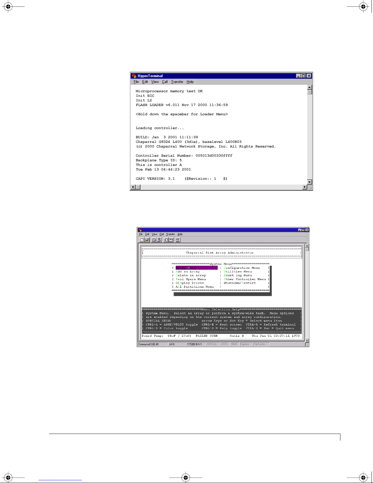
4100FS.book Page 83 Tuesday, July 8, 2003 4:35 PM
The initial Boot and POST screens are displayed.
Chapter 5 - Accessing the RAID Controllers
Boot and POST Screen
2 Following the Boot and POST screens the System Menu is displayed.
System Menu Screen
3 You can now perform all of the functions described in the following
chapters. All steps start from the System Menu.
If an event has occurred, you will see a message about the problem. This
message will also be stored in the event log.
Accessing the Disk Array Administrator Software/VT-100
83
Page 96
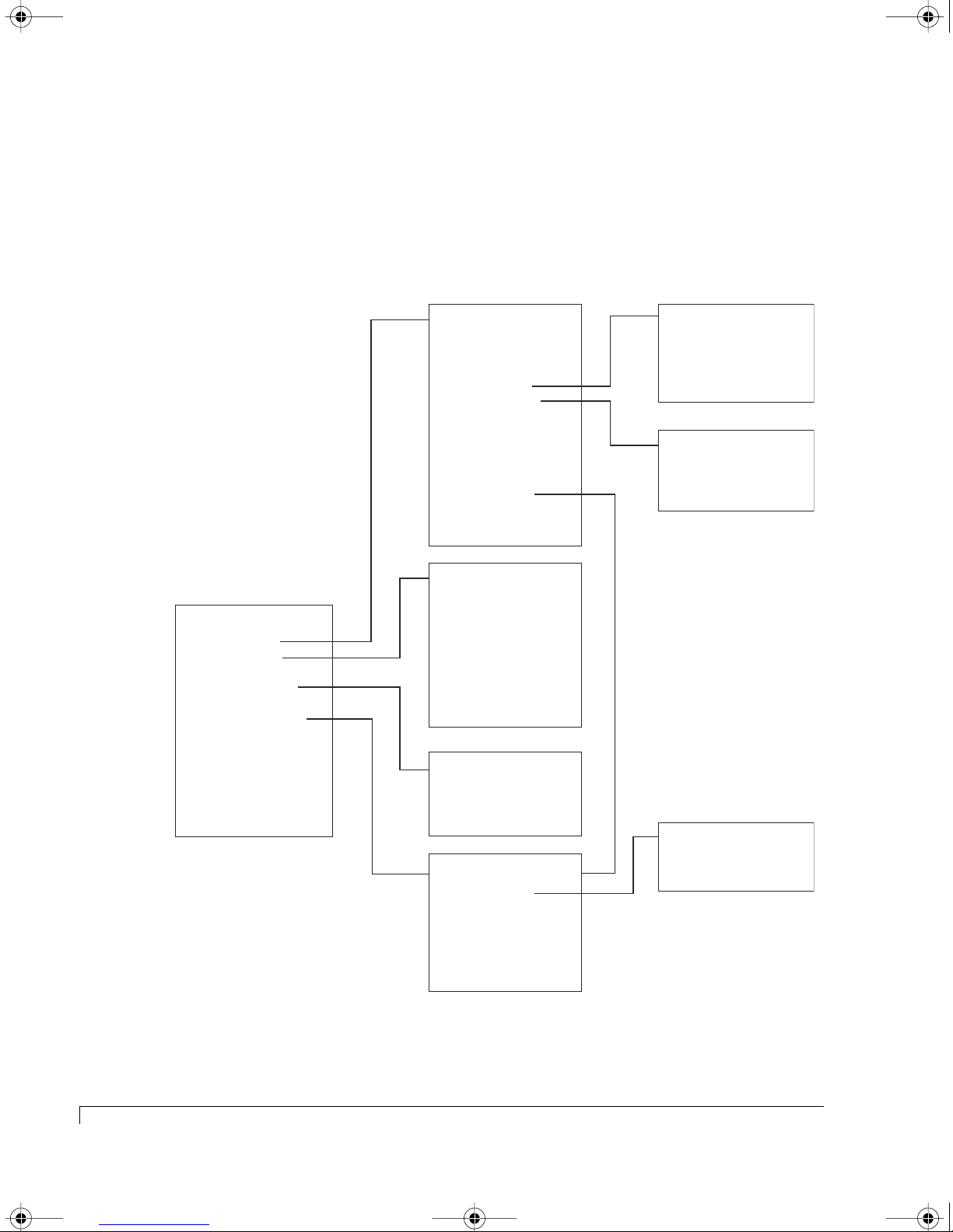
4100FS.book Page 84 Tuesday, July 8, 2003 4:35 PM
Chapter 5 - Accessing the RAID Controllers
Menu System
Below and on the next page are charts of the menu system for the onboard Disk
Array Administrator software. These are provided to assist you with quickly
locating a specific software function within the menu system.
System Menu
Array Menu
Add an Array
Delete an Array
Pool Spare Menu
Display Drives
All Partitions Menu
Configuration Menu
Utilities Menu
Event Log Menu
Other Controller Menu
Shutdown/Restart
Array Menu
Array Status
Drive Status
Abort Initialization
Verify Function
Expand Function
Add Spare
Delete Spare
Change Array name
Trust Array
Switch Array Owner
Partition Menu
Add a Partition
Delete a Partition
Add an Array
Enter Array Name
Single Partition
Enter LUN
Select RAID Type
Number of Drives
Select Drives
Chunk Size
Number of Spares
Pool Spare Menu
Display Pool Spare
Add Pool Spare
Delete Pool Spare
Partition Menu
Partition Status
Partition Statistics
Expand Partition
Change LUN
Change Partition Name
Delete This Partition
Verify Function
Start Verify
View Verify Status
Abort Verify
Expand Function
Start Expand
View Expand Status
Partition Statistics
View Statistics
Reset Statistics
84
Menu System
Disk Array Administrator Software Menu 1 of 2
Page 97
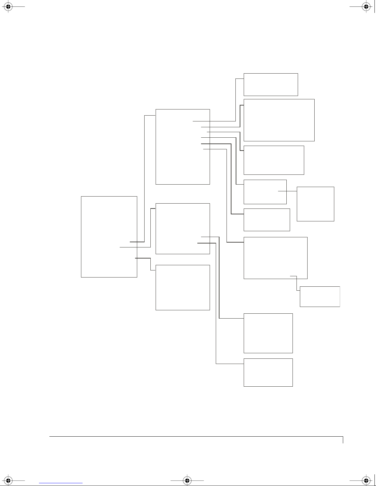
4100FS.book Page 85 Tuesday, July 8, 2003 4:35 PM
Menu System (continued)
System Menu
Array Menu
Add an Array
Delete an Array
Pool Spare Menu
Display Drives
All Partitions Menu
Configuration Menu
Utilities Menu
Event Log Menu
Other Controller Menu
Shutdown/Restart
Configuration Menu
Set Date/Time
Host Configuration
Channel Configuration
SEP Configuration
Disk Configuration
Option Configuration
Backoff Percent
Utility Priority
Alarm Mute
New Sample Rate
Restore Defaults
Utilities Menu
Rescan
Hot Swap Pause
Hardware Information
LUN Information
Drive Utilities Menu
Overall Statistics
Other Controller Menu
Other Information
Kill Other
Unkill Other
Shutdown Other
Shutdown Both
Chapter 5 - Accessing the RAID Controllers
Set Date/Time
Set Time
Set Date
Host Configuration
Channel
Enable/Disable
Link Speed
Target ID
Controller LUN
Topology (Loop or Point-to-Point)
Channel Configuration
Channel
Bus Speed
Disable Domain Validation
SEP LUNs
SEP Settings
SEP LUN
Disk Configuration
Write-Back Cache
SMART
Option Configuration
Operating Mode
Cache Lock
Battery
Enable Trust Array
Dynamic Spare Configuration
Enclosure Features
SEP Settings
Poll Rate
Temperature
Slot Flags
Global Flags
Enclosure Services
Config Internal Hubs
Connect I. Hubs on FO
Drive Utilities Menu
Blinik Drive LED
Clear Metadata
Down Drive
Test Unit Ready
Display Drive Cache
Overall Statistics
View Statistics
View R/W Histogram
Reset All Statistics
Disk Array Administrator Software Menu 2of 2
Menu System
85
Page 98
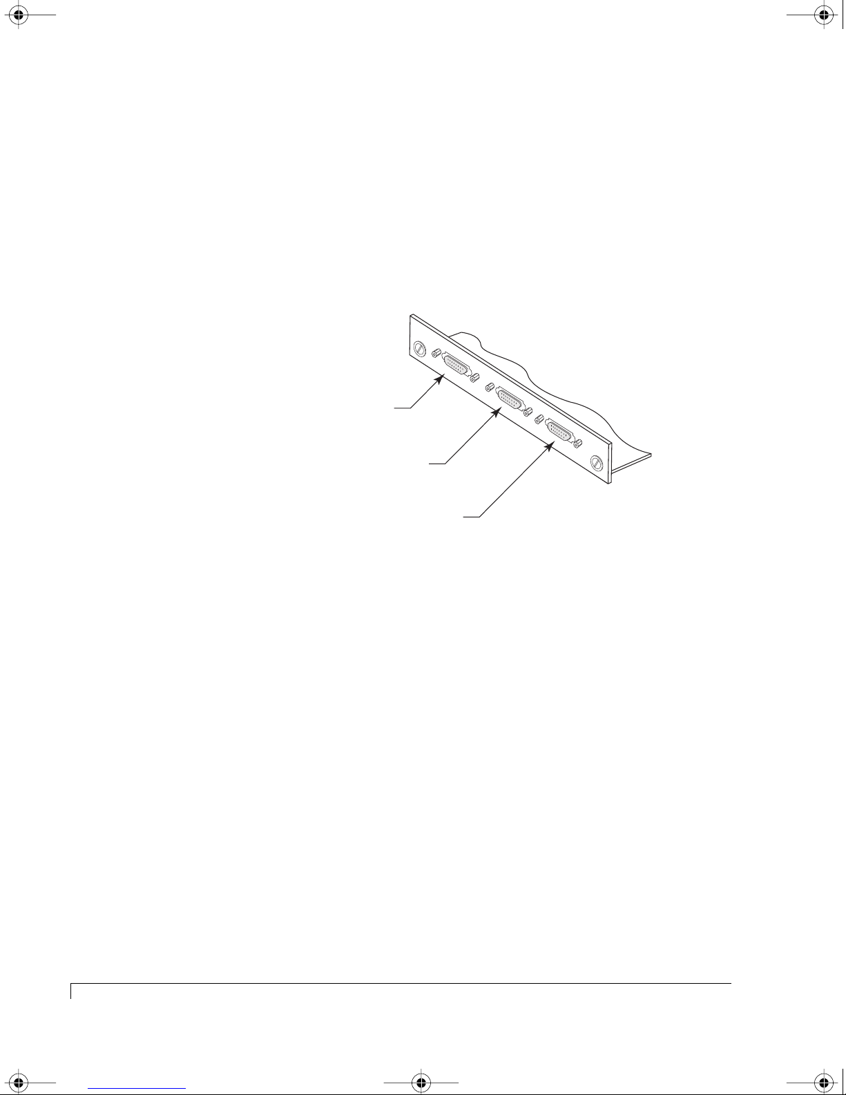
4100FS.book Page 86 Tuesday, July 8, 2003 4:35 PM
Chapter 5 - Accessing the RAID Controllers
Updating RAID Controller Firmware
The following information describes the procedures to upload new firmware to
the RAID Controllers. The firmware is uploaded when the controller’s are offline
and during the boot process.
1 Connect one end of the null-modem RS-232 cable to the RAID Controller 1
Service port located on the rear panel of the enclosure.
Controller 1: Service Port
CTRL 1
SAF-TE
CTRL 2
SAF-TE Service Port
Controller 2: Service Port
Connecting the Serial Cable
The cable is a female-to-female DB-9 null-modem serial cable.
2 Connect the other end of the cable to either a host system’s serial
communication port or a VT-100 type terminal.
3 On a host system, run a terminal emulation program or start the terminal.
4 Verify the communication parameters are as follows:
• 115,200 Baud
This is the speed at which the controller is communicating.
• 8 Data bits
• 1 Stop bit
• None (parity)
• Flow Control Off
5 Boot the RAID Controller Enclosure.
6 When the boot information appears on the screen press the <Space Bar>.
86
Updating RAID Controller Firmware
Page 99

4100FS.book Page 87 Tuesday, July 8, 2003 4:35 PM
Chapter 5 - Accessing the RAID Controllers
FLASH Loader Screen
7 Select option “3” xmodem by pressing the <3> key.
FLASH Loader Waiting for Transfer Selection Screen
8 Using the mouse, click on the pull-down menu Transfers and select “Send.”
Updating RAID Controller Firmware
87
Page 100

4100FS.book Page 88 Tuesday, July 8, 2003 4:35 PM
Chapter 5 - Accessing the RAID Controllers
9 Click the browse button and locate the new Firmware file and click “Send.”
The firmware file will have a “.fla” extension.
NOTE: Ensure that the protocol “Xmodem” is selected.
Send File Screen
From the Xmodem send screen you can monitor the progress of the upload.
You can safely stop the transfer without affecting your existing firmware any
time during the transfer until it has been completed. The upload does not
overwrite the firmware during the upload process, it writes the new code
into unused EEPROM space until completed, then copies the new firmware
code to the EEPROM active region.
If you elect to stop an upload progress, ensure that the stop (abort)
command was completed by typing <Control-X> at the cursor.
10 After the upload is successful, the Flash Loader will reboot the controllers.
During the reboot it will bring the second controller offline, if applicable, and
update its firmware.
88
Updating RAID Controller Firmware
 Loading...