

Page 1
SURGERY SYSTEM
OPERATION MANUAL
OM-E0262E
0197
Page 2

• Keep out from explosive substances and flammable materials. Do not use for patients
anesthetized with nitrous oxide gas especially.
• The system may present a possibility of malfunction when used in the presence of
electromagnetic interference wave. Do not install the system in the vicinity of the device
which emits magnetic waves. Turn off the power switch of the Control Unit of this system
when an ultrasonic oscillation device or an electrode knife located in the vicinity is used.
• Surgic XT is intended for use in dental, oral surgical, and surgical procedures. Do not use
in operating rooms due to potential flammable gas mixtures present in such environment.
• Patient safety is a priority.
• Read this Operation Manual before use, and fully understand the functions of each part
for starting use.
• Inspect the operating status of the equipment before use, and use only after confirming
that no abnormalities exist.
• Test run the product to ensure its correct operation prior to using it.
• If the product should ever malfunction (excessive vibration, noise, heat, etc) please turn it
off immediately and return it to your Authorized Dealer for inspection.
• When the product is very frequently used please consider the maintenance of a small
stock of replaceable parts.
• Use the equipment only after preparing spares for consumable parts. In particular, the
preliminary head SGM easily fails as a result of intrusion of blood or saline solution,
therefore, be sure to prepare spare parts.
• Use an electrical outlet that is grounded.
• To avoid possible injury or product damage, ensure that the Micromotor has completely
stopped before changing burs.
• Severe shock – Eg. Dropping the product – may cause damage.
• Do not bend the Irrigation Tube while the water pump is operating. It could cause tube
breakage.
• Never attempt to disassemble the Control Unit, the Foot Control or the Micromotor.
•
Handpiece Attachments should be cleaned, lubricated and sterilized immediately after use.
• Do not lubricate the Micromotor. Oil could generate excessive heat and cause damage.
• The Control Unit and the Foot Pedal Controller cannot be sterilized by any method.
• The Control Unit may be cleaned with a moist cloth. Disconnect the power supply before
cleaning.
• Do not clean the Control Unit with any solvent solutions.
• Do not disconnect the motor cord from the motor.
• Make sure that the cover is not fitted during calibration.
• Be sure to dispose of the irrigation tube as medical waste after use.
• The system functions normally in the environment where the temperature is at 0-40ºC (32104ºF), humidity at 10-85% RH, atmospheric pressure at 500- 1060hPa, and no moisture
condensation in the Control Unit. Use at outside of these limits may cause malfunction.
S Classification of equipment
• Type of protection against electric shock :
– Class l equipment
• Degree of protection against electric shock :
– Type BF applied part
• Method of sterilization or disinfection recommended by the manufacture :
– See 8. Sterilization
• Degree of protection against ingress of water as detailed in the current edition of IEC 529 :
– Foot Control : IPX8 (Protected against the effects of continuous immersion in water)
• Degree of safety of application in the presence of a flammable anesthetic mixture with air
or with oxygen or nitrousoxide :
– EQUIPMENT not suitable for use in the presence of a flammable anesthetic mixture with
air or with oxygen or nitrousoxide
• Mode of operation :
– Continuous operation
IMPORTANT
For correct operation please read this manual before use.
CONTENTS
1. Safety precautions prior to use
2. Package contents
3. Control unit with an irrigation pump
4. Foot control
5. Installation
6. Operation
7. Care and maintenance
8. Sterilization
9. Optional accessories
10. Specifications
11. Disposing product
SAFETY CAUTIONS
Read these safety cautions thoroughly before use and operate the product properly.
These indicators are to allow you to use the product safely and prevent danger and harm to you
and others. These are classified by degree of danger, damage and seriousness. All indicators
concern safety, be sure to follow them.
Indicators of Hazardous Conditions
1
2
3
5
6
9
11
13
14
14
14
••••••••••••••••••••••••••••••••••••••••••
•••••••••••••••••••••••••••••••••••••••••••••••••••••••••
••••••••••••••••••••••••••••••••••••
•••••••••••••••••••••••••••••••••••••••••••••••••••••••••••••••••
••••••••••••••••••••••••••••••••••••••••••••••••••••••••••••••••••
•••••••••••••••••••••••••••••••••••••••••••••••••••••••••••••••••••
••••••••••••••••••••••••••••••••••••••••••••••••••••
•••••••••••••••••••••••••••••••••••••••••••••••••••••••••••••••••
••••••••••••••••••••••••••••••••••••••••••••••••••••••
••••••••••••••••••••••••••••••••••••••••••••••••••••••••••••••
•••••••••••••••••••••••••••••••••••••••••••••••••••••••••
Safety precautions prior to use
1
q
Classification
WARNING
CAUTION
NOTICE
Degree of Danger or Danger and Seriousness
Explains an instruction where personal injury or physical damage may occur.
Explains an instruction where minor to medium injury or physical damage may occur.
Explains an instruction that should be observed for safety reasons.
WARNING
CAUTION
• Turn off the Power Switch after each use.
• For service requirements and spare parts please contact your dealer.
• The use of NSK genuine pre-sterilized, disposable Irrigation Tube Kit is recommended.
• Store the system in the place where the temperature is at -10-60ºC (14-140ºF), humidity at
10-85%RH, atmospheric pressure at 500-1060 hPa, and the system is not subject to air
with dust, sulfur, or salinity.
NOTICE
Thank you for purchasing the NSK Surgic XT, surgical unit.
The EU directive 93/42/EEC was applied in the design and production of this medical
device.
Page 3
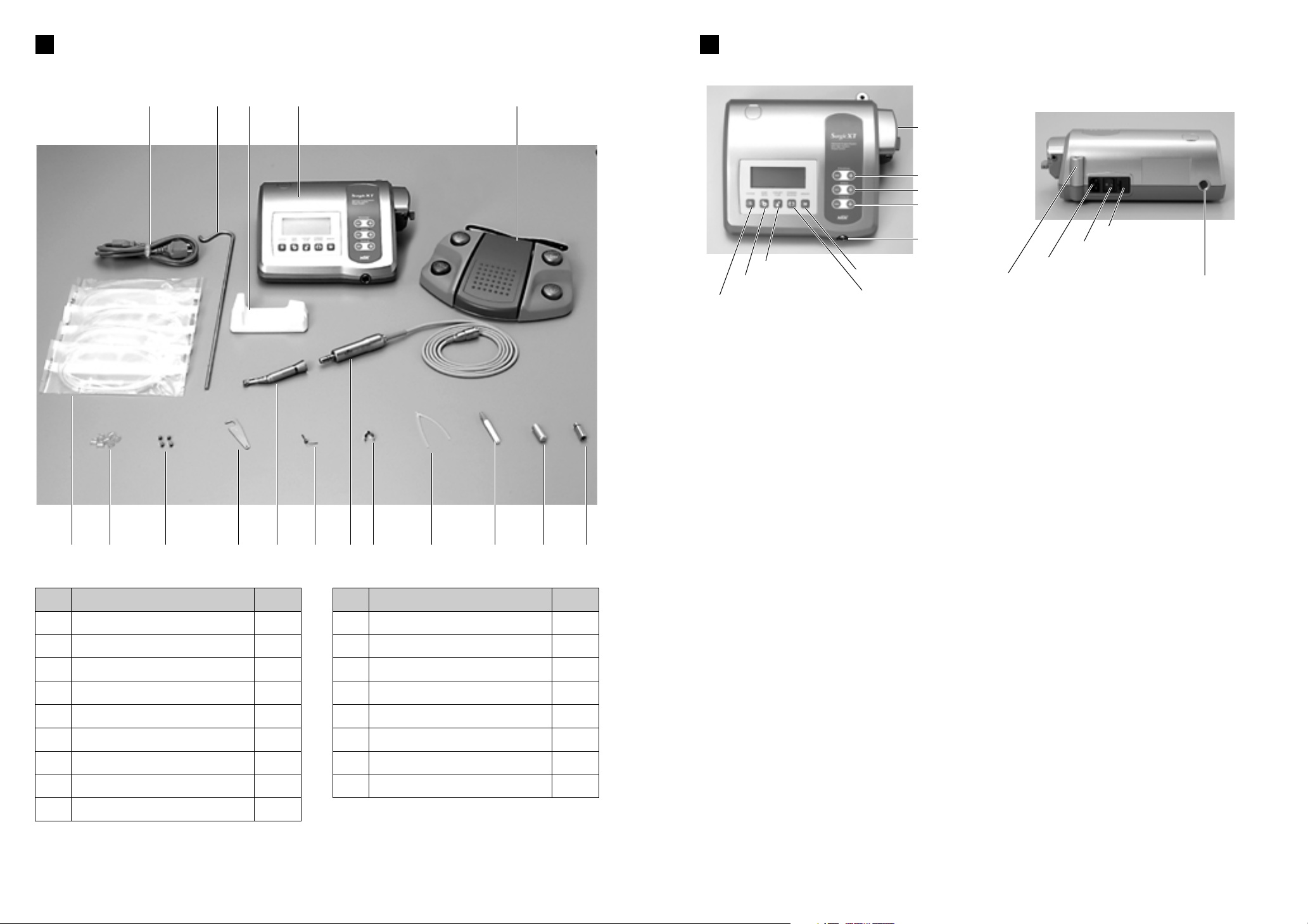
Description of Operation
S Keys on the Unit
a Program key
This key is used to select any one of 10 available programs. Press [+] to ascend program
numbers and [-] to descend the numbers. By pressing either [+] or [-] the numbers rotate
continuously through all available programs.
s Speed key
This key is used to set the micromotor speed. Press [+] to increase speed by one step, and [-]
to decrease speed by one step. When [+] is pressed and the speed setting reaches maximum
or [-] is pressed and the speed setting reaches minimum, an audible intermittent beep sounds,
and the speed cannot be changed any further.
d Torque key
This key is used to set the torque. Press [+] to increase torque by one step and [-] to decrease
torque by one step. When [+] is pressed and the torque setting reaches maximum, or [-] is
pressed and the torque setting reaches minimum, an audible intermittent beep sounds, and the
torque cannot be changed any further. The range of torque setting steps vary according to the
gear ratio selected to match the handpiece attachment in use.
f System key
This key is used to calibrate the handpiece attachment before use. To activate the automatic
calibration mode, connect the handpiece attachment to the micromotor and press this key. The
micromotor will automatically operate for a few moments and, when it automatically stops, the
handpiece attachment will be calibrated to the micromotor.
g Gear Ratio key
This key is to select match ratio of the handpiece attachment, before use, to the unit. Press this
key until the LCD display exhibits the correct gear ratio of the handpiece attachment.
h Coolant Flow key
This key is used to select the coolant solution flow volume. 5 flow volume rates are available for
selection, plus the flow can be turned off.
j Forward/Reverse key
This key is used to change the rotational direction of the micromotor. Press this key once to
change the rotational direction.
k Memory key
This key is used to memorize the program parameters set by the operator. Press this key for
approx. 1 second to memorizes parameters. An audible beep confirms that new program
parameters have been memorized.
ew
Gear Ratio key
Coolant Flow key
Forward/Reverse key
System key
Memory key
Speed key
Program key
Torque key
Coolant Solution Hanger Post
AC Electrical Cord Connection Jack
Fuse Holder
Main Power Switch
Micromotor Cord
Jack
Foot Control Cord Jack
Package contents
Irrigation Pump
2
u !0 !3
e !1 y q w
!2 t i r o !4 !5 !6 !7
q
w
e
r
t
y
u
i
o
Quantity
1
1
1
1
1
1
5
1
1
Description
Control Unit with Irrigation Pump
Foot Control
AC Electrical Cord
Autoclavable Micromotor with Cord
Reduction Handpiece Attachment (Opt)
Micromotor Cradle
Irrigation Tube
Internal Spray Nozzle
Irrigation Tube Clamp
Item
No.
!0
!1
!2
!3
!4
!5
!6
!7
Quantity
7
1
1
2
1
1
1
1
Description
Tube Holder
Coolant Solution Hanger Post
Wrench for Handpiece Attachment
Spare Fuse
Y-connector
Nozzle Cleaning Fine Wire
Autoclave Plug for Motor
Spray Lubricant Nozzle
Item
No.
Control Unit with an Irrigation Pump
3
Page 4

PRG (Program) button
Foot Control
cord and plug
Speed/Torque button
Forward/Reverse
button
Speed Control pedal
Program Number Gear Ratio
Coolant flow level
Speed/Torque Bar Graph
Forward/Reverse
Speed/Torque
Coolant solution flow
volume button
a Coolant Flow
Displays the selected coolant solution flow volume level. The selected flow volume level is
indicated by one of 5 levels of light. No light indicates the coolant solution flow is off.
s Program Number
Displays the selected program number.
d Gear Ratio
Displays the gear ratio of the handpiece.
f Forward/Reverse Indicator
Displays the rotational direction of the micromotor.
g Speed/Torque
Displays the selected speed and torque. Normal speed is shown when the unit is switched on
and also when a program is changed. To display speed, press the [Speed] key on the Control
Unit. To display torque, press the [Torque]. Speed and torque can also be displayed by pressing
the Speed/Torque button on the foot control.
✻ When the gear ratio is a constant speed or when using the Speed Increasing Handpiece,
the torque is not displayed.
h Speed/Torque Bar Graph
During operation displays an approximate percentage indication of the actual operating speed
or torque relevant to the preset maximum speed or torque. When all bars illuminate, the
operating speed or torque is at maximum. When bars are half illuminated then the operating
speed is approximately 50% of the preset speed.
S LCD display on the unit console
r t
CAUTION
The LCD display panel is produced from liquid crystal and should always be
treated with care.
a Coolant Solution Flow Volume button
This button is used to select the volume of coolant solution flow. Five levels are available and
each level may be increased by one step pressing this button once only. The step above level 5
and below level one turns the flow off.
s PRG (Program) button
This button is used to select the desired program number. Program numbers will always ascend
each time this button is pushed and will roll from No. 10 program onto No. 1 program. When the
button is pushed too many times and the wrong program is selected, press the button for 1
second more. It could get back to one program before the selected program.
d Speed Control Pedal
This pedal is used to start and stop the micromotor and to vary the speed during operation.
f Forward/Reverse button
This button is used to change the rotational direction of the micromotor. Push once to change
rotational direction.
g Speed/Torque button
This button is used to change the LCD display from Speed to Torque or vice versa. Push once
only to change the display.
Foot control
4
Page 5

Tube Guide
Position
Position
lrrigation Tube
Needle End
Stopper
Installation
5
5-4 Installing the Irrigation Tube
Mount the irrigation tube in the irrigation pump, with
the irrigation tube needle toward backside of the unit.
Position the stoppers of the tube in the guide
securely. (Fig.6)
5-5 Mounting the coolant solution bottle
Insert the coolant solution bottle hanger post into the
holder on the Control Unit. Place the bottle as shown
in Fig.10.
Only after the tubes are correctly positioned, close
the pump cover by turning the pump cover lever 90
degrees to the left Fig.8.
5-1 Connecting the motor cord
Face the [] mark on the Micromotor Cord plug
upward then insert the plug into the Micromotor
Cord jack on the Control Unit (Fig.1).
A click is heard when the motor cord plug is
correctly inserted into the control unit. To
disconnect the plug, pull back the lock joint, then
disconnect the cord (Fig.2).
5-2 Connecting the foot control
Face the screw on the foot pedal control cord
plug downward then insert the plug into the Foot
Control cord jack on the Control Unit. Secure the
plug by fastening the lock nut. See Figs.3 and 4.
5-3 Connecting the electrical power cord
Align correctly then insert the electrical power
cord into the power cord connection at the back
of the control unit (Fig.5).
uy
Fig.1
Fig.2
Fig.3
Fig.4
Fig.5
Base of micromotor
cord jack
Lock nut
Screw
Lock joint marking
CAUTION
Make sure that the tube is securely set on
the rollers when closing the pump cover.
If the tube is not correctly positioned on
the rollers and the cover is closed, the
tube could be cut or sheared. (Fig.7)
Rollers
Fig.7
Fig.6
Fig.8
Fig.9
Fig.10
Pump cover lever
Pump roller
Page 6

Bottle Cap
lrrigation
Tube Needle
Tube Clamp
Tube Cap
Power Switch
Symbol Mark
Function OFF ON
6-1 Programming the micromotor operation
The control unit can memorize 10 sets of programs. Each program includes the following
functions which will be automatically performed when the appropriate program number is
selected.
Gear ratio of contra angle handpieces
Speed
Direction of rotation
Torque upper limit
Coolant solution flow
a Turn on the power by pushing the main switch toward [-].
Whenever the main power switch is turned ON, program
number 1 is always displayed.
s Select a program number by using either step a) or step b):
O a Press the [Program] key on the unit control panel
until the program number you require is displayed OR
O b Press the [Program] button on the foot control until the program number
you require is displayed.
d Selecting the gear ratio of the handpiece relevant to the program
Press the [Gear Ratio] key the gear ratio of the handpiece to be used is displayed.
f Setting the speed
Set the speed by pressing the [Speed] key.
-Each time this key is pressed the display changes to the next speed level. By pressing this key
for more than 1 second brings the speed quickly to the next level until the speed display
reaches its upper or lower limit.
-When the speed setting reaches the upper or the lower limit, an audible beep is heard and the
speed setting cannot be changed any further.
g Setting the torque upper limit
Set the torque upper limit by pressing the [Torque] key on the unit control panel.
-Each time this key is pressed the display changes to the next torque level. By pressing this key
for more than 1 second brings the torque quickly to the next level until the torque display
reaches its upper or lower limit.
-When the torque setting reaches the upper or the lower limit, an audible beep is heard and the
torque cannot be changed any further.
h Select the rate of coolant solution flow volume
Select the rate of the coolant solution flow volume by pressing the [Coolant Flow] key.
-The rate of coolant solution flow volume has 5 flow rate steps plus "no coolant flow".
j Memorize settings
After completing steps 1-6 press the [Memory] key for more than 1 second until a long
audible beep is heard. The long beep confirms that the programming is completed. If you hear a
short audible beep when the [Memory] key is first pressed please ignore this signal and
keep the [Memory] key depressed until a long beep is heard.
Repeat the above steps 1-7 to program any one of the 10 available programs.
5-6 Insertion of the irrigation tube
a Place the coolant solution bottle on the hanger post
and insert the irrigation tube needle into the bottle
cap. (Fig.11)
s Close the tube clamp, between the irrigation tube
needle and the irrigation pump, as shown in Fig.12
d Open the tube cap to supply air into the bottle.
(Fig.13)
5-7 Mounting the internal spray nozzle
It is possible to connect water to the external
irrigation nozzle (Fig.14) and the internal
irrigation nozzle (Fig.15) simultaneously.
Simply connect the Y connector (Fig.16) onto
the main water supply tube at the rear of the
handpiece then connect the 2 water supply
tubes.
5-8 Attaching the tube holder
Use the tube holder to combine together the
motor cord and the irrigation tube. It is easier
to insert motor cord first and, next, the
irrigation tube.
Operation
6
oi
CAUTION
Do not operate the irrigation pump if the
tube is bent or the tube clamp is in the
closed position. This could cause the tube
to burst or slip out of the bottle.
Fig.11
Fig.12
Fig.13
Fig.14
Fig.15
Fig.16
Fig.17
Motor cord
Tube holder
Irrigation tube
Y-connector
PROGRAM
SPEED
TORQUE
Page 7

7-1 Protection circuit
An electronic circuit breaker automatically functions to protect the micromotor and the control
unit if the micromotor is ever overloaded. Power supply to the micromotor will automatically be
terminated and the Error code will be displayed on the control unit.
S Resetting the protection circuit
To reset the protection circuit, release and then depress the speed control pedal or push the
system key on the control unit.
7-2 Error Code
If an operational problem occurs the display shows the Error code to allow an immediate
problem diagnosis.
6-2 Calibration of the Handpiece to be used
The resistance of a handpiece attachment against the rotation of the micromotor varies slightly
depending on the handpiece model, its age and condition, the degree of wear on the handpiece
gears, and so on. The Surgic XT unit incorporates an automatic function to recognize the level
of the resistance of any handpiece attached to the micromotor, and to calibrate the micromotor
to rotate the handpiece attachment to the specific speed and torque settings required.
a Attach the handpiece to the micromotor and remove the bur.
s Press the [System] key for approx. 3 seconds until a long beep is heard. "CAL" is displayed.
d Press the [Gear Ratio] key and select the gear ratio of the attached handpiece.
f Press the [System] key again. After a moment the micromotor will automatically starts to run.
After a short series of resistance diagnosis is completed, the display returns to normal display
and the micromotor will automatically stop. Calibration of the handpiece is now completed.
6-3 Standard operation
All standard operational functions can be controlled at the foot control.
a Turn on the Main Switch
The Control Unit is ready to perform the program memorized in program number 1.
s Select the desired program number
Step on the foot control PRG [Program] button and the program display ascends to the next
program number. Select the desired program number as displayed on the control unit. The
program numbers ascend to 10 and then continue on to program 1. Pressing the PRG [Program]
Button for one second more could get back to one program before the selected program.
d Verify the details of the program
Verify the details of the program on the display.
The largest numerals displayed exhibit the speed setting. To verify torque, step on the foot
control Speed / Torque button and the speed display changes to the torque setting display.
f Operating the micromotor
Step on the speed control pedal in the middle of the foot control and the micromotor will start to
run. When the coolant solution flow is programmed to operate the pump will also automatically
run. Speed increases as the pedal is depressed. When the pedal is fully depressed the speed
reaches the maximum set value.
g Activation of the torque limiter
During operation of the micromotor, when the drilling load reaches the programmed torque
upper limit the integrated torque limiter automatically activates in to prevent torque application
excessive to the set requirement. When the torque limiter activates, the motor stops over
beeping after 5 seconds. To reactivate the micromotor simply press the [ System ] key.
h Stopping the micromotor
Release the foot control pedal, and the micromotor will automatically stop.
j Reversing the micromotor rotational direction
To reverse direction of the micromotor (and bur) simply step on the foot control Forward /
Reverse button. A warning beep can be heard when the rotational direction is in reverse mode.
Care and maintenance
7
!1!0
CAUTION
• Because the handpiece AUTOMATICALLY starts to run, any bur must be
removed from the handpiece before beginning the calibration process.
Leaving a bur in the handpiece may cause harm to the operator.
Care should be exercised not to ever add any load to a handpiece during
calibration, because an incorrect diagnosis would result in incorrect
torque control.
•
If “FAIL” is displayed on the liquid crystal panel, check the mounting of
each part and operate again. If “FAIL” is still displayed, contact your dealer.
CAUTION
This equipment is optimized to obtain the highest accuracy at a gear ratio of
1/20. When using another gear ratio, please note that the accuracy
decreases with an increase in the ratio relative to 1/20.
Erroneous memory.
Memory failure.
Extended use under heavy load.
Short circuit in the power cord.
Short circuit in the motor cord.
Main power cord failure.
Micromotor sensor failure (Hall IC).
Micromotor cord failure.
Signal line failure.
Overheating by extended use
under heavy load.
Operation of the unit under an
extremely high temperature.
Abnormal voltage generated in the
start / stop switch circuit.
Failure in the start / stop switch
circuit.
Handpiece attachment failure.
Micromotor failure.
When the motor stops for more
than 5 seconds after
reaching the torque upper limit.
Cause of Error
Request repair.
Electrical contact may be
insufficient.
Securely re-connect the motor
cord.
When an error cannot be
eliminated, request repair.
Allow it to cool down before use.
In order that heat is sufficiently
radiated, periphery of the main unit
should be well-ventilated wherever
possible.
When an error cannot be
eliminated, request repair.
When rotation and stop are repeated in short frequencies, a circuit
may be activated which limits acceleration at start. Wait a few seconds and then use.
When an error cannot be eliminated, request repair.
The chuck may be opened, or may
not be sufficiently closed.
Securely close the chuck.
When an error cannot be
eliminated, request repair.
This is not a failure. It stops for
safety reasons.
When the error is reset, this can
be used as it is.
Remedy
System Error
Excessive Current
Detected
Excessive Voltage
Detected
Motor Sensor Error
Unit Interior
Over-heating Error
Braking Error
Motor Rotation
Failure Error
Cause of Error
E 0
E 1
E 2
E 3
E 4
E 5
E 6
Error Code
Display
Page 8

120V
230V
T3.15AL 250V
T1.6AL 250V
The following items are autoclavable.
• Handpiece
• Micromotor with cord
• Motor handpiece cradle
• Internal coolant nozzle
• Irrigation tube clamp
• Tube holder
• Autoclave plug for micromotor
[ Autoclaving ]
a Remove blood and debris from the handpiece.
s Clean inside the handpiece, by using the spray lubricant (refer to "7. Care and Maintenance").
Do not attempt to spray lubricant into the micromotor.
Attach the micromotor autoclave plug to the micromotor.
d Place the handpiece in an autoclave pouch (not included in the package) and seal it.
f Autoclave for 20 min. at 121˚C (250˚F), or 15 min. at 132˚C (270˚F).
7-3 Replacement of the fuse
If the control unit does not function, check the fuses.
To access the fuse box simply squeeze the fuse box
lock located on the side of the control unit (Fig.18). If
the lock is too tight use a
pointed tool to squeeze the
lock.
7-4
Maintenance of the Control Unit and Foot Control
If blood or saline solution is stained on the Control
Unit or Foot Control, remove the power code, wipe
off the Unit or Foot Control with the cloth water
squeezed dry, and wipe off with the alcoholabsorbed cloth.
7-5
Maintenance of the handpiece attachment
After each operation, immerse the head in clean,
warm water and repeat run-stop of the motor four or
five times to rinse out blood or saline solution from
the handpiece head. If the handpiece exterior is
heavily stained, wash off with water, and dry with a
soft cloth. Do not immerse the entire handpiece in
water and prevent water from entering from back
end of the handpiece.
[ Using a Spray Lubricant ]
As shown in Fig.19, insert the spray lubricant can EType nozzle into the back of the handpiece. Spray
the lubricant into the handpiece 2-3 times for 2-3
seconds each time.
If the handpiece head is excessively stained with
blood or debris then remove the head by unscrewing
the nut with the supplied wrench (Fig.20). Attach the
specific head lubrication nozzle onto the spray
lubricant can and spray directly into the head to
wash away blood and debris. (Fig.21)
If the coolant nozzle is clogged use the Nozzle
cleaning fine wire supplied. Push it into the nozzle to
unclog it. (Fig.22)
When debris or dirt accumulates around the coolant
nozzle use the cleaning brush supplied (Fig.23).
Sterilization
8
!3!2
CAUTION
• Hold the handpiece and the spray can
securely or the handpiece may eject
from your hand due to the high pressure
of the spray.
• Shake the spray can a few times to mix
well the lubricant and the propellant.
• Hold the spray can upright for spraying.
Caution for autoclaving
• Clean and lubricate the handpiece before autoclaving. Autoclaving a
handpiece stained with blood or debris could cause damage to the
handpiece.
• Do not lubricate the micromotor.
• Do not use the autoclave drying cycle if the temperature at this cycle could
exceed 135˚C (275˚F).
• The Irrigation Tube is a single use disposable type and cannot be
autoclaved.
Fig.18
Fig.19
Fig.20
Fig.21
Fig.22
Fig.23
Fuse
Fuse box
Fig.24 Fig.25
Autoclave Plug Motor
Page 9

Please consult with dealer from whom you purchased it about waste disposal.
Disposing Product
11
14
Optional Accessories
NSK Surgical Handpieces
Part No. Model No.
Description
Bur Speed
10-1 Control Unit with Irrigation Pump
10-2 Micromotor
Specifications
10
9
RemarksDescriptionPart No.
Used for branching the internal and external coolant irrigation.
(See Fig.16 for installation)
For replacement tube use.
Supplied as standard accessory items.
Supplied as standard accessory items.
Supplied as standard accessory items.
Supplied as standard accessory items.
Y-Connector
Irrigation Tube
Internal Irrigation Tube
Tube Clamp
Tube Holder
Spray lubricant
C823-752
Z263-001
C293-025
C202-750
Y900-083
Z017-100
Type
Power Supply Voltage
Frequency
Power Consumption
Max. Pump Output
Dimensions
Weight
Speed Range
Input Voltage
Dimensions
Weight
200 - 40,000min
-1
(rpm)
DC30V
ø 24 x L120mm
133g (Without the motor cord)
NE111
AC120 / 230V
50/60Hz
48VA
75mL / min. (.02 gal/min.)
W268 x D230 x H103mm
3.1kg
C293
Y200-830
Y200-890
Y200-880
Y200-840
Y200-850
C221
C332
C295
H084
H083
SGM-I
SGM-E16RI
SGM-E20RI
SGM-E32RI
SGM-E64RI
SGM-E256RI
FBG-E
ES-85
ES-95
SGS-E
SGA-E
Min.
–
12.5
10
6.25
3.125
1.56
800
1,000
1,000
200
200
Max.
–
2,500
2,000
1,250
625
156
160,000
200,000
200,000
40,000
40,000
Mini latch head
16:1 speed reduction E-type sheath with mini latch head
20:1 speed reduction E-type sheath with mini latch head
32:1 speed reduction E-type sheath with mini latch head
64:1 speed reduction E-type sheath with mini latch head
256:1 speed reduction E-type sheath with mini latch head
1:4 speed increase E-type sheath with FG head, push-button
1:5 speed increase E-type sheath with mini FG head, push-button
1:5 speed increase E-type sheath with FG head, push-button
1:1 speed E-type straight handpiece
1:1 speed E-type angled handpiece
 Loading...