

Page 1
PRECAUTIONS
CAUTION
Fig. 1
Fig. 2
Fig. 3
Fig. 4
• Patient's safety is the first priority during treatment.
• Phatelus Light Pack is to be used by qualified personnel for
dental treatment only.
• If abnormal conditions arise during use, stop immediately and
contact your dealer.
• Never disassemble or modify.
• Do not subject unit to strong shocks.
• Do not pull on the AC adaptor cord.
• Never cut or shorten the AC adaptor cord because voltage will
increase and cause the lamp to fail easily.
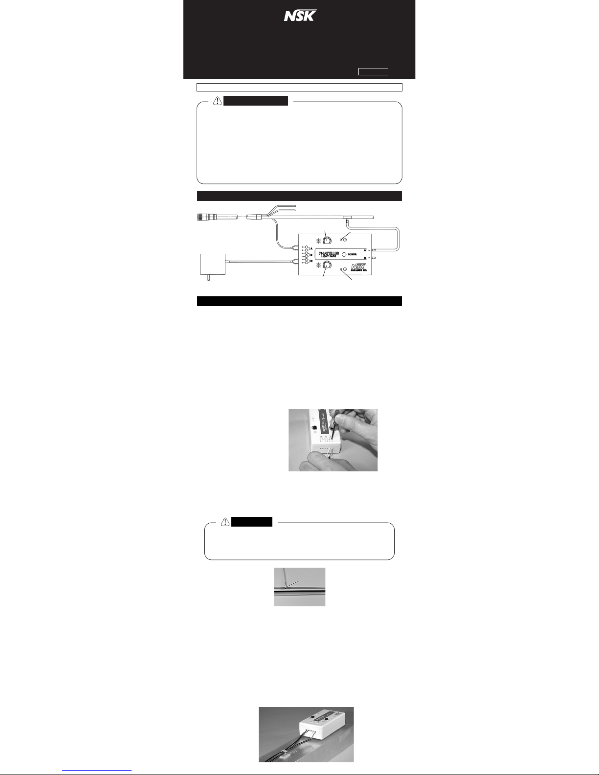
1. SET-UP DIAGRAM
2. CONNECTION
1) Assembling in Dental Unit
If AC/DC24V terminal is available inside of the dental unit, AC
adaptor is not required. Take out AC or DC24V power source line
from the dental unit and insert the end of the line into the hole of
Light Pack marked IN. If the power source is DC24V, no
consideration need be given to the plus and minus polarities.
2) Connection of AC Adaptor Lead Wire
Connect the Lead Wire from the AC adaptor to the hole maked IN
as shown in Fig.1.
Insert the Lead Wire from the AC adaptor into the hole located on
the side of Light Pack. Insert the screw driver provided in the hole
marked IN to release the spring clip and push in the lead wires to
connect. (Fig.2)
This AC adaptor has the
polarity of plus and minus
but the lead wire can be
connected to any hole in
any order marked IN.
3) Connection of Lead Wire from Tubing
Insert the Lead Wire from tubing into the hole marked A or B in the
same manner as you connected the Lead Wire from AC adaptor.
When connecting two Lead Wires from two tubings, use both the
A and B holes, one wire for each hole.
4) Installation of T-joint
Cut the drive air tubing and install T-joint. (Fig.3)
Connect by-pass tubing from T-joint to the same letter nipple as
the lead wire.
If installing 2 handpieces, the letters of the lead wires and the bypass tubings must be matched.
Application of a small amount of oil on the nipple makes it easy to
insert the by-pass tubing.
5) Installation of Light Pack
Install the Light Pack out of the way, underneath the work table or
on the underside of the arm with double faced tap.
Fasten the lead wires with the clips provided so they do not hang
down. (Fig.4)
Please read this Operation Manual carefully and file for future reference.
PHATELUS LIGHT PACK
OPERATION MANUAL
OM-E0039E Rev.2
Never cut the lead wire even it is too long because the
voltage will increase and the lamp will fail easily.
If the wire is too long, please bundle the remaining wire
and place where it will not be desturbed.
Tubing PTL-4H
AC Adaptor
AC Adaptor Lead Wire L=5,000
B Illuminance
Adjustment Knob
T-joint
B Illumination Time Delay
Adjustment Hole
Chip Air Tubing
Water Tubing
Drive Air Tubing
A Illuminance Adjustment Knob
A Illumination Time Delay
Adjustment Hole
Lead Wire
L=700
ClipClip
Page 2
CAUTION
Fig. 5
Fig. 6
Fig. 7
Fig. 8
3. CONNECTION OF AIR TURBINE TUBING
1) If your existing tubing is connected with a burr sleeve and the
Phatelus Light Pack tubing can be connected as it is, carefully
connect the water and the chip air tubing without mixing them up.
2) If your existing tubing is connected with a burr sleeve but the
Phatelus Light Pack tubing is not able to be connected due to the
difference in tubing size, cut the existing tubing about 5cm from
the end of the burr sleeve connector and connect with the straight
burr sleeve provided. (Fig.5)
4.
ADJUSTMENT OF ILLUMINANCE AND ILLUMINATION TIME DELAY
5. SPECIFICATIONS
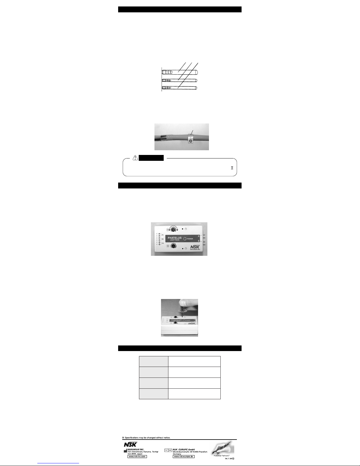
1) Adjustment of Illuminance
By turning Illuminance Adjustment Knob for A or B terminal, the
brightness of illuminatuin of the air turbine handpiece can be
adjusted. Max. illuminance is obtained by turning the adjustment
knob fully clockwise. Minimum illuminance is obtained by turning
the adjustment knob fully counter-clockwise. (Fig.7)
2) Adjustment of Illumination Time Delay
Illumination Time Delay can be adjusted by inserting the
screwdriver provided in the Illumination Time Delay Adjustment
Hole for A or B terminal and turning. Max. delay time (about
4.5sec.) is obtained by turning the screwdriver fully clockwise.
Minimum delay time is obtained by turning the driver fully counterclockwise. (Fig.8)
3) If your existing tubing is connected with a special metal fitting by
the unit manufacturers, contact Nakanishi or an authorized dealer.
4) If your existing tubing is fixed to the inside of unit, use the stopper
provided as shown in Fig.6.
When ordering tubing, please specify the tubing for
Phatelus Light Pack (PTL-4HP). The tubing for Phatelus Cpower pack may not be able to connect properly.
Existing Air Turbine Tubing
Stopper
Min. Max.
Power Source
(AC Adaptor)
Output Power
(Power Pack)
Illumination
Time Delay
Weight
(Power Pack)
AC/DC 24V
(AC 120V, 230V, 50-60Hz)
DC 2V ~ 3.5V
About 0.5 ~ 4.5Sec.
110g
 Loading...