

Page 1

Page 2
12
12
11
1
3
2
1
2
1
4
2
5
11
3
6
Page 3
12
Pana-Max2 PTL QD Coupling
Align
13
14 15
16 17
11
7
10
8
Midwest
4-Hole
Borden
2-Hole
11
9
12
Page 4
Align
13
Pana-Max2 PTL QD Coupling
16 17
14 15
Page 5
18
Page 6

1. User and Intended Use
User : Qualified Professionals
Intended Use : Dental Treatment
2. Precautions for handling and operation
•Please read these precautions carefully and use only as intended or
instructed.
•Safety instructions are intended to avoid potential hazards that could
result in personal injury or damage to the device. Safety instructions
are classified as follows in accordance with the seriousness of the risk.
Class
WARNING
CAUTION
NOTICE
Hazard that could result in serious injury or
damage to the device if the safety instructions are
not correctly followed.
Hazard that could result in light or moderate injury
or damage to the device if the safety instructions
are not correctly followed.
General product specification information
highlighted to avoid product malfunction and
performance reduction.
Degree of Risk
WARNING
•DepressingthePushButtonwhilethehandpieceis
inrotationmayleadtooverheating,causingburn
injuriesorproductfailure.Avoidthepushbutton
tocontactwithanyoraltissue.
1
Page 7

CAUTION
•Read this Operation Manual before use to fully understand the
product functions and file for future reference.
•When operating the product always consider the safety of the
patient.
•Users are responsible for the operational control, maintenance and
continual inspection of this product.
•Do not attempt to disassemble the product nor tamper with the
mechanism except as recommend by NSK in this Operation
Manual.
•Do not allow any impact on to the product. Do not drop the product.
•Operators and all others in the area must wear eye protection and
a mask when operating this handpiece.
•Should the product function abnormally, cease operation
immediately and contact your Authorized NSK Dealer.
•Do not use high acid water or sterilizing solutions to wipe, immerse
or clean the product.
•The products are delivered in a non-sterile condition and must be
2
autoclaved prior to use.
•Perform regular function and maintenance checks.
•If the product is not used for a long period check it is functioning
correctly before using on a patient.
•To avoid clinical downtime it is recommended that a spare be kept
on hand in case of a breakdown during surgery.
•U.S. Federal law restricts this device to sale by or on the order of a
licensed physician.
3. Setting of Air & Water Supply Pressure
Measure the supply pressure at the handpiece / hose connection point
and set the pressure to the value specified on the specification table.
(Fi g.1)
For Multi Gauge information refer to Option Parts List.
WARNING
•Donotexceedtheoptimumpressurespecifiedon
thespecificationtable.
Page 8
CAUTION
•Do not use air contaminated by dust, moisture and oil.
4.
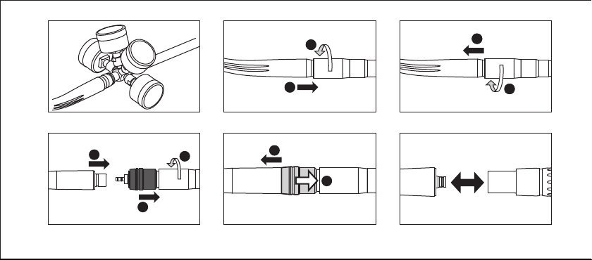
Connection & Disconnection of the Handpiece
Refer to Operation Manuals of coupling and hose before connecting the
handpiece.
Pana-Max2 M4/Pana-Max2 B2
4-1-1 Connection
1) Insert the handpiece correctly into the hose connector and tighten
the hose nut. (Fig.2)
2) Make sure the handpiece is connected firmly to the hose.
4-1-2 Disconnection
Loosen the Hose Nut and remove from the Hose. (Fig.3)
Pana-Max2 QD
4-2-1 Connection
1) Insert the coupling into the hose connector and tighten the hose
nut. (Fig.4)
2) Insert the handpiece to the coupling while pulling back the
retention lock ring of the coupling. Release the retention lock ring.
3) Make sure the handpiece is firmly connected to the coupling.
4-2-2 Disconnection
Pull back the Retention Lock Ring and remove the handpiece from the
Coupling. (Fig.5)
Pana-Max2 PTL
4-3-1 Connection
1) Insert the handpiece into the Coupling. (Fig.6)
2) Make sure the handpiece is firmly connected to the coupling.
4-3-2 Disconnection
Pull back the Retention Lock Ring and remove the handpiece from the
Coupling. (Fig.7)
CAUTION
•Do not operate the Retention Lock Ring while under drive air
pressure. The high pressure may cause sudden release of the
handpiece from the coupling.
3
Page 9

5. Insertion & Removal of the Bur
5-1 To Insert the Bur
1) Insert the bur until it is correctly seated in place. (Fig.8)
2) Depress the Push Button and insert the bur into the chuck until it is
secure then release the button.
3) Ensure that the bur is secure by gently pulling and pushing the bur
WITHOUT depressing the Push Button.
5-2 To Remove the Bur
Depress the Push Button firmly and remove the bur.
NOTICE
•Grip the handpiece while placing your thumb tip on the Push
button which makes it easier to depress the button.
4
CAUTION
•Always insert the bur all the way into the chuck.
•Remove the bur only after the handpiece has completely stopped
rotating.
•Always keep the bur shank clean. Entry of debris into the chuck,
via the bur shank, could cause bur rotation slip and also prevent
the bur from being securely located in the chuck.
•Do not exceed the bur speed recommended by the bur
manufacturer.
•Do not exceed maximum bur length recommended by the
handpiece manufacturer.
•Do not apply excess pressure to the bur as it may break or bend or
become difficult to remove.
•DO NOT use burs with problems listed below as the bur may break
or disengage from the chuck.
Bent, deformed, anisomerous (worn), rusted, broken, deficient bur.
-
Bur which is cracked on the edge or axis.
-
-
Non-ISO standard, or tampered bur.
Page 10

6. Check before treatment
Check that the Head Cap is firmly tightened. Also check for handpiece
vibration, noise and overheating. If any abnormalities are found do not
use the handpiece and contact your Authorized NSK Dealer.
7. Maintenance
After each patient maintain the product as follows.
7-1 Cleaning handpieces with the N SK Clean-Head System
After the treatment of each patient, clean the Clean Head.
1) Remove dirt and debris from the Clean Head Holes with the brush.
(Fig.9)
2) Half fill a cup with clean water.
3) Rotate the handpiece and immerse half of the handpiece head in
the cup of water. (Fig.10)
4) Rotate then stop intermittently the handpiece 3 times for 2 to 3
seconds each time.
5) Wipe the handpiece dry.
*If the dirt could not be removed from the hole, clean it by brush.
7-2 Cleaning (Handpiece)
1) Remove dirt and debris from the product. Do not use a wire brush.
2) Wipe clean with alcohol-immersed cotton swab or cloth.
This icon denotes that the product can be washed via Thermo
Disinfector.
Refer to the Thermo-Disinfector manual.
CAUTION
•After washing with Thermo-Disinfector and prior to lubrication,
dry the product until all internal moisture is thoroughly removed.
Thermo-Disinfector moisture remaining inside the product could
reduce the effect of lubrication and could cause corrosion inside
of the product.
•To clean the product never use any solvent such as benzine or
thinner.
5
Page 11

7-3 Lubrication
NSK PANA SPRAY Plus
Pana-Max2 M4/Pana-Max2 B2
Apply NSK PANA SPRAY Plus every time after each use and/or before
autoclaving.
1) Remove the handpiece from the hose.
2) Remove the bur from the handpiece.
3) Mount the Tip Nozzle into the spray can port. (Fig.11)
4) Insert the Tip Nozzle into the Drive Air Port of the handpiece. Hold
the handpiece and spray for approximately 2-3 seconds. Apply
lubricant until it expels from the handpiece head for at least 2
seconds. (Fig.12)
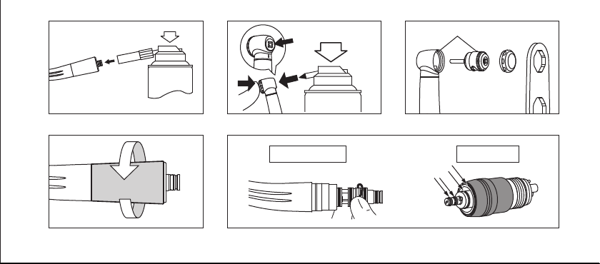
Pana-Max2 QD/Pana-Max2 PTL/Pana-Max2 KV
Apply NSK PANA SPRAY Plus every time after each use and/or before
autoclaving.
1) Remove the bur from the handpiece.
2) Insert the Spray Nozzle into the Spray Port nozzle on the can.
3) Insert the Spray Nozzle in rear of the handpiece. Hold the
handpiece and spray for approximately 2-3 seconds. Apply
6
lubricant until it expels from the handpiece head for at least 2
seconds. (Fig.13)
CAUTION
•When applying spray be sure to hold the handpiece firmly to
prevent the handpiece from slipping out of the hand due to the
spray pressure.
•Hold the spray can upright.
Page 12

Chuck cleaning
Clean Push Button chuck once a week.
1) Mount the Tip Nozzle into the spray can port.
2) Lubricate the chuck directly through the bur insertion hole. (Fig.14)
3) Lubricate the handpiece by using NSK PANA SPRAY Plus (Fig.11,13)
or NSK automatic handpiece cleaning and lubrication system.
CAUTION
•If the chuck is not regularly cleaned the chuck grip may be
weakened and the bur may be accidentally released while in
operation.
NSK automatic handpiece cleaning and lubrication system
When using NSK automatic handpiece cleaning and lubrication
system, refer to the system instructions.
7-4 Sterilization
Sterilize the product by autoclave sterilization. Remove the bur after
each patient and sterilize as noted below.
1) Insert into an autoclave pouch. Seal the pouch.
2) Autoclavable under the conditions below.
Autoclave for more than 20 min. at 121°C, or 15 min. at 132°C, or
3 min. at 134°C.
3) The handpiece should remain in the autoclave pouch until required
for use.
CAUTION
•Do not autoclave the product with other instruments even when it
is in a pouch. This is to prevent possible discoloration and damage
to the product from chemical residue on other instruments.
•Keep the product in suitable atmospheric pressure, temperature,
humidity, ventilation, and sunlight. The air should be free from
dust, salt and sulphur.
7
Page 13

•Immediately after use, the product should be cleaned, lubricated
and sterilized. If blood remains on the external or internal surfaces
it can become clotted and cause rust.
•Do not heat or cool the product too quickly. Rapid change in
temperature could cause damage to the product.
•If the sterilizer chamber temperature may exceed 135°C during
the dry cycle then delete the dry cycle.
•Autoclave sterilization is recommended for the product. The
validity of other sterilization methods is not confirmed.
•Do not touch the product immediately after autoclaving as it will be
very hot and must remain in a sterile condition.
NOTICE
•NSK recommends Class B sterilizers as stated in EN13060.
8
8. Replacing the Cartridge
1) Insert a test bur.
2) Locate the correct wrench tool on the head cap then turn the
wrench counter clockwise to loosen the cap. Remove the cap.
3) Use the bur to gently lever the entire cartridge out from the head.
4) Clean the head interior with NSK PANA SPRAY Plus.
5) Wipe the NSK PANA SPRAY Plus oil over the head interior.
6) Insert the new cartridge into the head by aligning the pin on the
cartridge with the slot on the head. (Fig.15)
7) Firmly tighten the head cap with the correct head cap wrench.
*Refer to Spare Parts List to identify the correct cartridge.
Page 14

CAUTION
•Use only a genuine NSK cartridge.
•If another cartridge is used NSK cannot guarantee performance
and the handpiece warranty would become invalid.
•Always first finger tighten the head cap then secure firmly with the
head cap wrench.
•NSK never recommends the disassembly and repair of any NSK
cartridge. There is NO EXCEPTION. In such a case a handpiece
may perform abnormally (abnormal noise or abnormal vibration).
Damage, failure or accidents are outside of our guarantee.
9. Replacing the O-rings
Replace the O-rings if water is present in the exhaust air line. This is
an indication of possible water leakage within the coupling. ALWAYS
change the complete set of O-rings.
(Pana-Max2 PTL/QD Coupling)
1) Loosen and Remove the taper ring at the rear of the handpiece.
(Fig.16) (Pana-Max2 PTL)
2) Gently remove each O-ring by hand. (Fig.17)
3) Insert the complete set of new O-rings in the correct grooves.
4) Replace and firmly tighten the taper ring. (Pana-Max2 PTL)
*Refer to Spare Parts List to identify the correct parts.
CAUTION
•Do not force the new replacement O-ring with excessive pressure.
•When inserting new O-rings, make sure they are inserted in the
correct grooves.
•Make certain that the taper ring is firmly tightened. If the taper
ring is loose water and air leakage could occur. (Pana-Max2 PTL)
9
Page 15

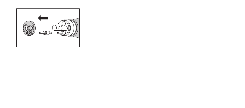
10. Replacing the Non-Retraction Valve
A water Non-Retraction Valve is integrated in the Coupling Joint, which
shuts off the water retraction directly at the handpiece head to prevent
fluids infiltrating the water line. If water is beginning to leak from the
handpiece, replace the non-retraction valve.
1) Remove the Coupling Joint from the hose.
2) Remove the back-end Gasket.
3) Pull and remove the water tube, and replace the Non-Retraction
Valve. (Fi g.18)
4) Insert the new Non-Retraction Valve securely and remount the
back-end Gasket.
*Refer to Spare Parts List to identify the correct parts.
10
(NSK Coupling/QD Coupling)
11. Periodical Maintenance Checks
Perform periodical maintenance checks every three months, referring
to the check sheet below. If any abnormalities are found, contact your
Authorized NSK Dealer.
Points to check
Head cap is loose
Rotation
Coolant Water
Tighten firmly using the correct head cap
wrench.
Rotate the handpiece and check for
abnormalities such as abnormal rotation,
vibration, noise, and overheating.
Operate the handpiece and check that the
coolant water is flowing through all spray ports.
Details
12. Symbol
This product is Autoclavable up to Max.135ºC.
This product can be washed via Thermo Disinfector.
Conforms to CE European Directive of “Medical device directive
93/42/EEC.”
Page 16
Manufacturer.
Authorized representative in the European community.
Caution: U.S. Federal law restricts this device to sale by or on the
order of a licensed physician.
13. Warranty
NSK products are warranted against manufacturing errors and defects
in materials. NSK reserves the right to analyze and determine the cause
of any problem. Warranty is voided should the product be not used
correctly or for the intended purpose or has been tampered with by
unqualified personnel or has had non NSK parts installed. Replacement
parts are available for seven years beyond discontinuation of the model.
14. Option Parts List
Model
MG-4H Multi Gauge
MG-2/3H Multi Gauge
Order Code
Z109400
Z109200
Compatible Product
Pana-Max2 M4
Pana-Max2 B2
15. Spare Parts List
Model
PAX2-SU03
PAX2-SU04
PAX2-SU05
PTL O-ring Set
QD O-ring Set
Non-Retraction Valve
Order Code
P1190
P1190050
P1190765
Y900580
Y900592
P401054
Remarks
Cartridge
Head Cap
Head Cap Wrench
Pana-Max2 PTL
QD Coupling
NSK Coupling/QD Coupling
16. Disposing product
In order to avoid the health risks of operators handling the disposal of
medical equipment, as well as the risks of environmental contamination
caused thereof, a surgeon or a dentist is required to confirm the
equipment is sterile. Ask specialist firms who are licensed to dispose of
specially controlled industrial wastes, to dispose the product for you.
11
Page 17

17. Specifications
Model
Hose Connection Type
Rotation Speed
Bur Type
Chucking Length
Max. Bur Length
Max. Working Part Diameter
Drive Air Pressure
Air Consumption
Water Pressure
Chip Air Pressure
Use Environment
Transportation and Store Environment
KaVo® and MULTIflex® are registered trademarks of Kaltenbach & Voigt GmbH & Co., Germany.
12
Pana-Max2 M4 Pana-Max2 B2 Pana-Max2 QD Pana-Max2 PTL Pana-Max2 KV
ISO 9168 Type 2
(Midwest 4 hole)
350,000 - 450,000min
ISO 9168 Type 1
(Borden 2 hole)
-1
For NSK QD Coupling
300,000 - 400,000min
ISO 1797-1 ø1.59 - 1.60mm Standard Bur
0.20 - 0.25MPa
(2.0 - 2.5kgf/cm
≤55 NL/min (0.25MPa)
0.15 - 0.25MPa
(1.5 - 2.5kgf/cm
2
)
0.05 - 0.20MPa (0.5 - 2.0kgf/cm
-
Temperature: 0 - 40°C (No Condendation), Humidity: 30 - 75%
Temperature: -10 - 50°C, Humidity: 10 - 85%, Atmospheric Pressure: 500 - 1,060hPa
For NSK Phatelus
-1
10.2mm
21mm
ø2mm
2
)
0.15 - 0.25MPa (1.5 - 2.5kgf/cm
Coupling
350,000 - 450,000min
2
)
®
MULTIflex®
For KaVo
Coupling
-1
0.25 - 0.30MPa
(2.5 - 3.0kgf/cm
≤55 NL/min (0.28MPa)
2
)
2
)
Page 18

1. Benutzer und Verwendungszweck
Benutzer : Qualifiziertes Fachpersonal
Verwendungszweck : Zahnmedizinische Behandlung
2.
Sicherheitsanweisungen für die Handhabung und Bedienung
•Lesen Sie bitte diese Sicherheitsanweisungen aufmerksam
durch und benutzen Sie das Gerät ausschließlich gemäß seines
bestimmungsgemäßen Gebrauchs und entsprechend der Anweisungen.
•Die Sicherheitsanweisungen sind dafür vorgesehen, mögliche Gefahren
zu verhindern, die Körperverletzungen oder Beschädigungen am Gerät
verursachen können. Die Sicherheitsanweisungen werden gemäß der
Schwere des Risikos wie folgt klassifiziert.
KLASSE
ACHTUNG
VORSICHT
HINWEIS
Ausmaß und Schwere der Gefährdung oder Schädigung
Risiko, das zu schweren Verletzungen oder
Schäden am Gerät führen kann, wenn die
Sicherheitshinweise nicht beachtet werden.
Ein mögliches Risiko, das zu leichten bis mittleren
Personen- oder Sachschäden führen kann, wenn
die Sicherheitshinweise nicht beachtet werden.
Allgemeine Produktinformationen, die besonders
hervorgehoben werden, um Störungen oder
Leistungsminderungen zu vermeiden.
ACHTUNG
•WennderDruckknopfbetätigtwird,währendsich
dasHandstückinRotationbefindet,kanneszu
ÜberhitzungundfolglichzuVerbrennungenoder
FehlfunktionendesGerätskommen.AchtenSie
darauf,dassderDruckknopfnichtinKontaktmitdem
Wangengewebekommt.
13
Page 19

VORSICHT
•Lesen Sie diese Betriebsanleitung vor dem Gebrauch sorgfältig
durch und machen Sie sich mit allen Bedienungsfunktionen
vertraut. Bewahren Sie die Betriebsanleitung so auf, dass sie für
die zukünftige Verwendung leicht auffindbar ist.
•Berücksichtigen Sie beim Betrieb des Produkts immer die
Sicherheit des Patienten.
•Der Benutzer ist für die Funktionsprüfung, Wartung und ständige
Überprüfung dieses Produkts verantwortlich.
•Versuchen Sie nicht, das Produkt auseinander zu bauen, und
nehmen Sie keine Änderungen am Mechanismus vor, es sei denn,
dies wird von NSK in diesem Handbuch empfohlen.
•Schützen Sie das Produkt vor Stößen. Lassen Sie das Produkt
nicht fallen.
•Bediener und alle anderen Personen in der Umgebung müssen
während der Benutzung dieses Handstücks einen Augenschutz tragen.
•Sollte das Produkt nicht einwandfrei funktionieren, stellen Sie den Einsatz
sofor t ein und nehmen Sie Kontak t mit Ihrem NSK-Fachhändler auf.
•Benutzen Sie kein Wasser mit hohem Säuregehalt oder
14
Sterilisationslösungen zum Abwischen, Eintauchen oder Reinigen
des Produkts. Legen Sie das Produkt nicht in solche ein.
•Die Produkte werden im unsterilen Zustand ausgeliefert und
müssen vor dem Gebrauch autoklaviert werden.
•Führen Sie in regelmäßigen Abständen Funktionsprüfungen und
Wartungen durch.
•Wenn das Produkt längere Zeit nicht benutzt wurde, müssen Sie
zunächst prüfen, ob es einwandfrei funktioniert, bevor Sie es am
Patienten anwenden.
•Es wird empfohlen, ein Reservegerät für den Fall eines Ausfalls
während einer Operation verfügbar zu haben.
•Ein U.S. Bundesgesetz schreibt vor, dass dieses Produkt nur durch einen
oder im Auftr ag eines lizenzierten Mediziners verk auft werden darf.
3. Einstellung des Luft- & Wasserdrucks
Messen Sie den Versorgungsdruck am Handstück / Schlauchanschluss
und stellen Sie den Druck entsprechend den Angaben in der Tabelle ein.
(Ab b.1)
Für Informationen zu Multi Gauge siehe Stückliste.
Page 20
ACHTUNG
•ÜberschreitenSienichtdeninderTabellegenannten
optimalenDruck.
VORSICHT
•Benutzen Sie keine durch S taub, Feuchtigkeit und Öl verunreinigte Luft.
4.
Verbinden & Abtrennen des Handstücks
Beachten Sie die Betriebsanleitungen der Kupplung und des Schlauchs,
bevor Sie das Handstück montieren.
Pana-Max2 M4/Pana-Max2 B2
4-1-1 Mon tag e
1) Führen Sie das Handstück ordnungsgemäß in den Schlauchanschluss
ein und ziehen Sie die Schlauchmutter an. (Abb.2)
2) Stellen Sie sicher, dass das Handstück fest mit dem Schlauch
verbunden ist.
4-1-2 Demontage
Schlauchmutter lösen und aus dem Schlauch entfernen. (Abb.3)
Pana-Max2 QD
4-2-1 Montage
1) Führen Sie der Kupplung in den Schlauchanschluss und ziehen Sie
die Schlauchmutter an. (Abb.4)
2) Führen Sie das Handstück in die Kupplung und ziehen Sie dabei
den Haltering der Kupplung zurück. Lassen Sie den Haltering los.
3) Stellen Sie sicher, dass das Handstück fest mit der Kupplung
verbunden ist.
4-2-2 Demontage
Ziehen Sie den Haltering zurück und entfernen Sie das Handstück von
der Kupplung. (Abb.5)
Pana-Max2 PTL
4-3-1 Montage
1) Führen Sie Handstück und Kupplung zusammen. (Abb.6)
2) Stellen Sie sicher, dass das Handstück fest mit der Kupplung
verbunden ist.
15
Page 21

4-3-2 Demontage
Ziehen Sie am Haltering und entfernen Sie das Handstück aus der
Kupplung. (Abb.7)
VORSICHT
•Betätigen Sie den Haltering nicht unter Druck. Der hohe Druck
kann zu einem plötzlichen Lösen des Handstücks von der
Kupplung führen.
5.
Einsetzen & Entfernen des Fräsers oder Schleifers
5-1 Einsetzen des Fräsers oder Schleifers
1) Führen Sie den Fräser/Schleifer ein, bis dieser korrekt an seinem
Platz eingesetzt ist. (Abb.8)
2) Betätigen Sie den Druckknopf und führen Sie den Fräser/Schleifer
in das Spannfutter ein, bis dieser sicher und fest eingesteckt ist.
Lassen Sie anschließend den Drucknopf los.
3) Stellen Sie sicher, dass die Fräse festsitzt, indem Sie vorsichtig
daran ziehen und drücken, OHNE dabei den Druckknopf zu
betätigen.
16
5-2 Entfernen des Fräsers oder Schleifers
Betätigen Sie den Druckknopfund entfernen Sie den Fräser/Schleifer.
HINWEIS
•Greifen Sie das Handstück, indem Sie das Handstück mit dem
Zeigefinger im vorderen Halsbereich fixieren. Dies erleichtert die
Betätigung des Druckknopfs mit dem Daumen.
VORSICHT
•Führen Sie den Fräser/Schleifer immer komplett in das Spannfut ter ein.
•Entfernen Sie den Fräser/Schleifer erst, wenn das Handstück
vollständig zum Stillstand gekommen ist.
•Halten Sie den Schaft des Fräsers/Schleifers stets sauber.
Das Eindringen von Fremdkörpern in das Spannfutter über den
Fräserschaft kann zu Schlupf führen und verhindern, dass sich der
Fräser/Schleifer fest ins Spannfutter einspannen lässt.
•Überschreiten Sie nicht die vom Hersteller des Fräsers/Schleifers
angegebene Drehzahl.
Page 22

•Überschreiten Sie nicht die von NSK empfohlene maximale
Fräser-/Schleiferlänge.
•Wenden Sie keinen übermäßigen Druck auf den Fräser/Schleifer
an, da dieser brechen oder sich verbiegen kann oder nur schwer
zu entfernen sein wird.
•Benutzen Sie KEINEN Fräser/Schleifer mit den unten genannten
Problemen, da dieser ansonsten brechen oder sich aus dem
Spannfutter lösen kann.
- Verbogener, verformter, anisomerer (verschlissener), verrosteter,
beschädigter, mangelhafter Fräser/Schleifer.
-Fräser mit einem Riss in der Kante oder in einer Achse.
- Fräser, der nicht der ISO-Norm entspricht oder in irgendeiner
Weise verändert wurde.
6. Überprüfung vor der Behandlung
Überprüfen Sie, ob der Kopfdeckel fest angezogen ist. Überprüfen Sie das
Handstück zudem auf Vibrationen, Geräusche und Überhitzung. Wenn Sie
irgendwelche Auffälligkeiten feststellen, darf das Handstück nicht benutz t
werden. Nehmen Sie in diesem Fall Kontakt mit Ihrem NSK-Fachhändler auf.
7. War tung
Führen Sie nach jedem Patienten die folgende Wartung des Produkts durch.
7-1 Reinigung von Handstücken mit dem Clean-Head-System von NSK
Reinigen Sie das Clean Head-System nach jeder Behandlung.
1) Entfernen Sie mit der Bürste Schmutz und Ablagerungen aus den
Clean Head-Öffnungen. (Abb.9)
2) Füllen Sie einen Becher halbvoll mit klarem Wasser.
3) Drehen Sie das Handstück und tauchen Sie den Handstückkopf
halb in den Becher mit Wasser ein. (Abb.10)
4) Lassen Sie das Handstück drei Mal ca. 2 bis 3 Sekunden lang im
Wasser abwechselnd laufen und stoppen.
5) Wischen Sie das Handstück trocken.
* Wenn der Schmutz sich nicht aus der Öffnung entfernen lässt,
reinigen Sie ihn mit der Bürste.
7-2 Reinigung (Handstück)
1) Entfernen Sie Schmutz und Ablagerungen vom Produkt. Benutzen
Sie keine Drahtbürste.
17
Page 23
2) Wischen Sie es mit einem in Alkohol getränkten Wattestäbchen
oder Tuch sauber.
Dieses Symbol bedeutet, dass das Produkt mittels
Thermodesinfektor gereinigt werden kann.
Beachten Sie die Bedienungsanleitung des Thermodesinfektors.
VORSICHT
•Lassen Sie das Produkt nach der Reinigung mittels Thermodesinfektor
und vor der Schmierung trocknen, bis die gesamte Feuchtigkeit
im Inneren entwichen ist. Feuchtigkeit des Thermodesinfektors im
Inneren des Produkts kann die Wirkung der Schmierung verringern
und Korrosion im Inneren des Produkts verursachen.
•Benutzen Sie für die Reinigung des Produkts niemals
Lösungsmittel wie Verdünner oder Benzin.
7-3 Schmierung
NSK PANA SPRAY Plus
Pana-Max2 M4/Pana-Max2 B2
Führen Sie nach jeder Benutzung und/oder vor der Autoklavierung
18
eine Ölpflege mit NSK PANA SPRAY Plus durch.
1) Entfernen Sie das Handstück vom Schlauch.
2) Entfernen Sie den Fraser vom Handstuck.
3) Montieren Sie die Öl-Sprühdüse (Spannzange; blau) auf der
Spraydose. (Abb.11)
4) Setzen Sie die Sprühdüse in die Antriebsluftöffnung des Handstücks
ein. Halten Sie das Handstück fest und sprühen Sie für die Dauer von
etwa 2-3 Sekunden. Tragen Sie Schmiermittel auf, bis esmindestens
2 Sekunden lang aus dem Handstückkopf austritt. (Abb.12)
Pana-Max2 QD/Pana-Max2 PTL/Pana-Max2 KV
Führen Sie nach jeder Benutzung und/oder vor der Autoklavierung
eine Ölpflege mit NSK PANA SPRAY Plus durch.
1) Entfernen Sie den Fräser vom Handstück.
2) Führen Sie die Sprühdüse in die Sprühöffnung an der Dose ein.
3) Setzen Sie die Sprühdüse auf der Rückseite des Handstücks ein.
Halten Sie das Handstück fest und sprühen Sie für die Dauer von
etwa 2-3 Sekunden. Tragen Sie Schmiermittel auf, bis es mindestens
2 Sekunden lang aus dem Handstückkopf austritt. (Abb.13)
Page 24
VORSICHT
•Stellen Sie beim Anwenden des Spray sicher, dass Sie das
Handstück festhalten, um zu verhindern, dass das Handstück bei
der Schmierung aufgrund des Spray-Drucks herausrutscht.
•Halten Sie die Dose aufrecht.
Reinigung der Spannzange
Reinigen Sie die Druckknopf-Spannzange einmal pro Woche.
1) Montieren Sie die Öl-Sprühdüse (Spannzange; blau) auf der Spraydose.
2) Schmieren Sie die Spannvorrichtung direkt durch die
Spannzangenöffnung. (Abb.14)
3) Schmieren Sie das Handstück mit NSK PANA SPRAY Plus (Abb.11,13)
oder mit dem automatischen Pflegegerät von NSK.
VORSICHT
•Wenn die Spannzange nicht regelmäßig gereinigt wird, treten
Abnutzungserscheinungen am Spannfutterhalter auf, wodurch
sich der Bohrer während des Betriebs versehentlich lösen kann.
automatisches NSK Pflegegerät
Bitte beachten Sie für die Verwendung des automatischen
Pflegegeräts von NSK die jew. Gebrauchsanweisung des Gerätes.
7-4 Sterilisation
Sterilisieren Sie das Produkt im Autoklaven. Entfernen Sie den Fräser /
Schleifer nach jedem Patienten und sterilisieren Sie es wie unten beschrieben.
1) Legen Sie das Gerät in einen Sterilisations-Beutel. Versiegeln Sie
diesen.
2) Autoklavierbar unter den unten genannten Bedingungen.
Autoklavierbar für mehr als 20 Min. bei 121°C, oder 15 Min. bei
132°C, oder 3 Min. bei 134°C.
3) Das Handstück sollte bis zum Gebrauch im Sterilisations-Beutel
verbleiben.
VORSICHT
•Autoklavieren Sie das Produkt nicht mit anderen Instrumenten,
auch dann nicht, wenn es sich in einem Beutel befindet. Dadurch
19
Page 25

wird eine mögliche Verfärbung und Beschädigung des Produkts
durch chemische Rückstände auf anderen Instrumenten vermieden.
•Lagern Sie das Produkt unter geeigneten Verhältnissen
hinsichtlich Luftdruck, Temperatur, Luftfeuchtigkeit, Belüftung
und Sonneneinstrahlung. Die Luft darf nicht staub-, salz- oder
schwefelhaltig sein.
•Das Produkt sollte unmittelbar nach dem Einsatz gereinigt,
geschmiert und sterilisiert werden. Wenn innen oder außen Blut
zurückbleibt, kann es gerinnen und Rost oder sonstige Schäden
verursachen.
•Produkt nicht zu schnell erhitzen oder abkühlen. Ein schneller
Temperaturwechsel kann das Produkt beschädigen.
•Falls die Sterilisationskammer während der Trocknung 135°C
überschreiten kann, überspringen Sie den Trocknungszyklus.
•Für das Produkt wird eine Autoklavsterilisation empfohlen. Die
Wirksamkeit anderer Sterilisierungsverfahren kann nicht bestätigt
werden.
•Berühren Sie das Produkt nicht sofort nach dem Autoklavieren, da
es sehr heiß ist und steril bleiben soll.
20
HINWEIS
•NSK empfiehlt Klasse B-Sterilisation nach EN13060.
8. Wechseln des Kopftriebs
1) Setzen Sie einen Testbohrer ein.
2) Fixieren Sie den korrekten Schraubenschlüssel am Kopfdeckel und
drehen Sie anschließend den Schraubenschlüssel entgegen dem
Uhrzeigersinn, um den Deckel zu lösen. Entfernen Sie den Deckel.
3) Benutzen Sie den Testbohrer, um den ganzen Einsatz vorsichtig
aus dem Kopf herauszuholen.
4) Reinigen Sie das Innere des Kopfgehäuses mit NSK PA NA SPRAY Plus.
5) Entfernen Sie überschüssiges Öl aus dem Inneren des
Kopfgehäuses, sodass lediglich ein feiner Ölfilm zurückbleibt.
6) Setzen Sie den neuen Einsatz in den Kopf ein, indem Sie den Passstift
am Einsatz korrekt mit dem Schlitz im Kopf ausrichten. (Abb.15)
7) Ziehen Sie den Kopfdeckel mit dem richtigen Kopfdeckelschlüssel
fest.
*Siehe die Liste mit den Ersatzteilen für den richtigen Einsatz.
Page 26

VORSICHT
•Benutzen Sie ausschließlich einen Original-NSK-Kopftrieb (Einsatz).
•Bei der Benutzung eines anderen Einsatzes kann NSK die
Leistungsfähigkeit nicht garantieren. Die Garantie für das
Handstück erlischt.
•Ziehen Sie den Kopfdeckel immer zunächst mit dem Finger fest und
ziehen Sie ihn anschließend mit dem Kopfdeckelschlüssel fest.
•NSK empfiehlt niemals das Zerlegen und die Reparatur eines
NSK-Kopftriebs. Es gibt KEINE AUSNAHME hiervon. In diesem Fall
kann das Handstück möglicherweise nicht mehr normal arbeiten
(ungewöhnliche Geräusche oder Vibrationen). Schäden, Ausfall
oder Unfälle fallen nicht unter unsere Garantie.
9.
Austausch der O-Ringe
Tauschen Sie die O-Ringe aus, falls Wasser in der Rückluftleitung
vorhanden ist. Dies lässt auf ein mögliches Wasserleck innerhalb der
Kupplung schließen. Tauschen Sie IMMER den kompletten Satz O-Ringe
aus.
(Pana-Max2 PTL/QD-Kupplung)
1) Lösen und entfernen Sie die Kupplungshülse hinten am Handstück.
(Abb.16) (Pana-Max2 PTL)
2) Entfernen Sie vorsichtig von Hand alle O-Ringe. (Abb.17)
3) Setzen Sie einen kompletten Satz neuer O-Ringe in die richtigen
Fräsungen ein.
4) Montieren Sie den die Kupplungshülse und ziehen Sie sie sicher
fest. (Pana-Max2 PTL)
*Sh. Ersatzteilliste zur Auswahl der korrekten Teile.
VORSICHT
•Wenden Sie beim Einsetzen der neuen O-Ringe keinen
übermäßigen Druck an.
•Stellen Sie sicher, dass die O-Ringe in die richtigen Fräsungen
eingesetzt werden.
•Stellen Sie sicher, dass die Kupplungshülse sicher festgezogen
ist. Bei locker sitzender Kupplungshülse können Wasser- und
Luftundichtigkeiten auftreten. (Pana-Max2 PTL)
21
Page 27

10. Austausch des Rückschlagventils
In der Kupplungsdichtung ist ein Rückschlagventil eingebaut, das
den Wasserrückfluss direkt am Handstückkopf abwehrt. Damit wird
vermieden, dass Flüssigkeit in die Wasserleitung zurück gesaugt
wird. Wenn Wasser aus dem Handstück austritt, ersetzen Sie das
Rückschlagventil.
1) Entfernen Sie die Kupplungsdichtung vom Schlauch.
2) Entfernen Sie die hintere Dichtung.
3) Ziehen Sie die Wasserleitung ab und entfernen Sie das
Rückschlagventil. (Abb.18)
4) Stecken Sie das neue Rückschlagventil fest ein und befestigen Sie
wieder die Dichtung am hinteren Ende.
*Sh. Ersatzteilliste zur Auswahl der korrekten Teile.
(NSK-Kupplung/QD-Kupplung)
11. Regelmäßige Wartungsprüfungen
Führen Sie alle drei Monate Wartungsprüfungen durch, siehe dazu die im
Folgenden aufgeführten Kontrollpunkte. Wenn Sie irgendeine Auffälligkeit
feststellen, nehmen Sie Kontakt mit Ihrem NSK-Fachhändler auf.
22
Prüfpunkte
Kopfdeckel ist
locker
Rotation
Kühlwasser
Ziehen Sie die Kopfkappe mit dem richtigen
Kopfdeckelschlüssel fest an.
Lassen Sie das Handstück laufen und überprüfen
Sie es auf Auffälligkeiten z.B. ungewöhnliche
Laufeigenschaften, Vibration, Geräusche und
Überhitzung.
Setzen Sie das Handstück in Betrieb und
überprüfen Sie, ob das Kühlwasser durch alle
Sprayöffnungen austritt.
Beschreibung
12. Symbol
Dieses Produkt kann bei bis zu max.135°C. autoklaviert werden.
Dieses Produkt kann mit einem Thermodesinfektor gereinigt und
desinfiziert werden.
Die EU-Richtlinie 93/42 /EEC wurde bei der Entwicklung und
Herstellung dieses medizinischen Gerätes angewendet.
Hersteller.
Page 28

Autorisierter Repräsentant in der Europäischen Gemeinschaft.
Vorsicht: Ein U.S. Bundesgesetz schreibt vor, dass dieses Produkt
nur durch einen oder im Auftrag eines lizenzierten Mediziners
verkauft werden darf.
13. Garantie
Für alle NSK-Produkte gilt eine Garantie für Fabrikationsfehler und Mängel
an Materialien. NSK behält sich das Recht vor, die Ursache von Problemen
zu analysieren und zu ermitteln. Die Garantie erlischt, wenn das Produkt
nicht ordnungsgemäß oder nicht sachgemäß verwendet wurde, das
Produkt von unqualifiziertem Personal verändert wurde oder Fremdteile
(Nicht-NSK-Teile) eingebaut wurden. Ersatzteile sind bis mindestens
sieben Jahre nach Einstellung der Produktion des Modells erhältlich.
14. Stückliste
Modell
MG-4H Multi Gauge
MG-2/3H Multi Gauge
Bestellnummer
Z109400
Z109200
kompatibel mit
folgendem/n Produkt/en
Pana-Max2 M4
Pana-Max2 B2
15. Ersatzteilliste
Modell
PAX2-SU03
PAX2-SU04
PAX2-SU05
PTL O-Ring-Satz
QD O-Ring-Satz
Rückschlagventil
Bestellnummer
P1190
P1190050
P1190765
Y900580
Y900592
P401054
Bemerkungen
Turbineneinsatz
Kopfdeckel
Kopfdeckel-Schlüssel
Pana-Max2 PTL
QD-Kupplung
NSK-Kupplung/QD-Kupplung
16. Entsorgung des Produkts
Zur Vermeidung von Risiken der Gesundheit des Benutzers bei der
Entsorgung der medizinischen Ausrüstung sowie des Risikos der
Umweltverschmutzung durch die Entsorgung der medizinischen
Ausrüstung muss ein Chirurg oder ein Zahnarzt bestätigen, dass die
Ausrüstung steril ist. Beauftragen Sie eine Fachfirma, die über eine
Zulassung zur Entsorgung von speziell kontrollierten industriellen
Abfällen verfügt, mit der Entsorgung des Produkts.
23
Page 29

17. Technische Daten
Modell
Schlauchanschluss
Drehzahl
Fräser-/Schleifertyp
Schaftlänge
Max. Fräserlänge
Max. Arbeitsteil-Durchmesser
Antriebsluftdruck
Luftverbrauch
Wasserdruck
Luftdruck
Benutzungsumgebung
Transport und Lagerort
KaVo® und MULTIflex® sind eingetragene Marken von Kaltenbach & Voigt GmbH & Co., Deutschland.
24
Pana-Max2 M4 Pana-Max2 B2 Pana-Max2 QD Pana-Max2 PTL Pana-Max2 KV
ISO 9168 Typ 2
(Midwest 4-Loch)
350.000 - 450.000min
ISO 9168 Typ 1
(Borden 2-Loch)
-1
ISO 1797-1 ø1,59 - 1,60mm Standard-Fräse
Für NSK QD
Kupplung
300.000 - 400.000min
10,2mm
0,15 - 0,25MPa
(1,5 - 2,5kgf/cm
0,20 - 0,25MPa
(2,0 - 2,5kgf/cm
≤55 NL/min (0,25MPa)
0,05 - 0,20MPa (0,5 - 2,0kgf/cm
2
)
-
2
Temperatur: 0 - 40°C (Keine Kondensation), Feuchte: 30 - 75%
Temperatur: -10 - 50°C, Feuchte: 10 - 85%, Atmosphärischer Druck: 500 - 1.060hPa
Für NSK Phatelus
-1
21mm
ø2mm
)
2
0,15 - 0,25MPa (1,5 - 2,5kgf/cm
Kupplung
350.000 - 450.000min
)
Für KaVo® MULTIflex®
Kupplung
-1
0,25 - 0,30MPa
(2,5 - 3,0kgf/cm
2
)
≤55 NL/min (0,28MPa)
2
)
Page 30

1. Utilisateur et finalité d'utilisation
Utilisateur : Professionnels qualifiés
Finalité d'utilisation : Soins dentaires
2.
Précautions à prendre lors de la manipulation et du fonctionnement
•Lisez soigneusement ces précautions et n'utilisez l'appareil qu’à des
fins indiquées et uniquement selon les instructions données.
•Les instructions de sécurité ont pour but d'écarter tout danger potentiel
pouvant déboucher sur des blessures corporelles ou endommager
l'appareil.
Les instructions de sécurité sont classées comme suit, selon la gravité
du risque.
Classification
AVERTISSEMENT
ATTENTION
REMARQUE
Niveau de danger ou danger et gravité
Le non-respect des instructions de sécurité risque
de provoquer des blessures graves ou
d'endommager l'appareil.
Le non-respect des instructions de sécurité risque
de provoquer des blessures légères ou
d'endommager l'appareil.
Informations générales relatives aux caractéristiques
du produit entrant ainsi un dysfonctionnement ou une
diminution des performances.
AVERTISSEMENT
•Lefaitd'appuyersurlebouton-poussoirpendant
quel'instrumenttournepeutentraînerune
surchauffeetdesbrûluresouunedéfaillancedu
produit.Évitezquelebouton-poussoirentreen
contactaveclabouche.
25
Page 31

ATTENTION
•Lisez ce mode d'emploi avant utilisation pour bien comprendre les
fonctions du produit et conservez-le.
•Lorsque vous utilisez le produit, veillez à toujours vous assurer de
la sécurité du patient.
•Les utilisateurs sont responsables des vérifications
opérationnelles, de l'entretien et de l'inspection permanente de
cet appareil.
•N'essayez pas de démonter le produit ou de modifier son
mécanisme, sauf si NSK vous le recommande dans ce mode
d'emploi.
•Veillez à ce que le produit ne soit soumis à aucun impact. Ne faites
pas tomber le produit.
•Les utilisateurs et toutes les autres personnes présentes dans la
pièce doivent porter des lunettes de protection et un masque lors
de l'utilisation de cet instrument.
•Si le produit ne fonctionne pas correctement, arrêtez immédiatement
de l'utiliser et contactez votre distributeur NSK agréé.
26
•N'essuyez pas, ne nettoyez pas ou n'immergez pas le produit dans
de l'eau fortement acide ou des solutions de stérilisation.
•Les produits sont livrés non stériles et doivent être stérilisés en
autoclave avant de les utiliser.
•Réalisez régulièrement des contrôles d'entretien et fonctionnels.
•Si le produit n'a pas utilisé pendant une période prolongée, vérifiez
son bon fonctionnement avant de l'utiliser sur un patient.
•Pour éviter les périodes d'indisponibilité, il est recommandé de
conserver un appareil de réserve en cas de panne durant une
opération chirurgicale.
•U.S. La loi fédérale limite ce dispositif à la vente par ou sur l'ordre
d'un médecin autorisé.
3.
Réglage de la pression d'alimentation en air & en eau
Mesurez la pression d'alimentation à l'endroit de connexion de la pièce à
main/du cordon et réglez la pression à la valeur spécifiée dans le tableau
de spécification. (Fig.1)
Pour la Multi Jauge, se référer à la liste des pièces en option.
Page 32

AVERTISSEMENT
•Nedépassezpaslapressionoptimalespécifiée
dansletableaudesspécifications.
ATTENTION
•N'utilisez pas d'air contaminé par de la poussière, de l'humidité ou
de l'huile.
4.
Connexion & déconnexion de la pièce à main
Pour la connexion de la pièce à main, se référer au mode d'emploi du
raccord et du cordon.
Pana-Max2 M4/Pana-Max2 B2
4-1-1 C on nexio n
1) Insérez la pièce à main dans le connecteur du cordon et serrez
l'embout du cordon. (Fig.2)
2) Assurez-vous que la pièce à main est fermement connectée au cordon.
4-1-2 Déconnexion
Desserrez l'embout du cordon et enlevez-le du cordon. (Fig.3)
Pana-Max2 QD
4-2-1 Connexion
1) Insérez le raccord dans le connecteur du cordon et serrez l'embout
du cordon. (Fig.4)
2) Insérez la pièce à main dans le raccord tout en tirant la bague de
serrage du raccord. Relâchez la bague de serrage.
3) Assurez-vous que la pièce à main est fermement connectée au
raccord.
4-2-2 Déconnexion
Enlevez la bague de serrage et retirez la pièce à main du raccord. (Fig.5)
Pana-Max2 PTL
4-3-1 Connexion
1) Insérez la pièce à main dans le raccord. (Fig.6)
2) Vérifiez que la pièce à main est fermement connectée au raccord.
27
Page 33

4-3-2 Déconnexion
Enlevez la bague de serrage de retenue et retirez la pièce à main de
son raccord. (Fig.7)
ATTENTION
•Ne manipulez pas la bague de serrage sous pression de l'air
d'entraînement. Cette pression élevée peut provoquer l'extraction
soudaine de la pièce à main du raccord.
5. Insertion & enlèvement de la fraise
5-1 Pour insérer la fraise
1) Insérez la fraise jusqu'à ce qu'elle soit bien correctement
positionnée. (Fig.8)
2) Appuyez sur le bouton-poussoir et insérez la fraise dans la griffe
jusqu'à ce qu'elle soit bien maintenue avant de relâcher le bouton.
3) Assurez-vous de la bonne tenue de la fraise en tirant-poussant
celle-ci doucement sans APPUYER sur le bouton-poussoir.
28
5-2 Pour retirer la fraise
Appuyez fermement sur le bouton-poussoir et enlevez la fraise.
REMARQUE
•Saisissez la pièce à main tout en plaçant votre pouce sur le bouton
poussoir ce qui facilite pour enfoncer le bouton.
ATTENTION
•Toujours insérer complètement la fraise dans la griffe.
•Ne retirez la fraise une fois que la pièce à main est complètement
arrêtée.
•Veillez à ce que le mandrin de la fraise soit toujours propre.
L'entrée de débris dans la griffe via le mandrin de la fraise peut
entraîner une mauvaise rotation par glissement et empêcher le
bon positionnement de la fraise dans la griffe.
•Ne dépassez pas la vitesse de la fraise recommandée par le
fabricant de la fraise.
•Ne dépassez pas la longueur maximale de fraise recommandée
Page 34

par le fabricant de la pièce à main.
•N'exercez pas une pression excessive sur la fraise pour ne pas la
briser ou la plier ou rendre son extraction difficile.
•N'UTILISEZ PAS de fraises présentant les problèmes énumérés
pour ne pas casser la fraise ou la détacher de la griffe.
- Fraise courbée, déformée, anisomère (usée), rouillée ou
défectueuse.
-Les fraises qui présentent une fissure sur leur bord ou leur axe.
- Les fraises qui ne sont pas standard ISO ou des fraises qui ont
été modifiées.
6. Vérification avant utilisation
Vérifiez que le couvercle de tête est fermement serré. Vérifiez également
que la pièce à main ne présente pas de vibrations, de bruit ni une
surchauffe. En cas d'anomalies, n'utilisez pas l'instrument et contactez
votre revendeur NSK agréé.
7. Maintenance
Après chaque patient, procédez à l'entretien du produit comme suit.
7-1 Nettoyage de pièces à main à l'aide du système Clean Head NSK
Après avoir soigné un patient, nettoyez le système Clean Head.
1) Enlevez les saletes et les debris des orifices du systeme Clean
Head a l'aide de la brosse. (Fig.9)
2) Remplissez à moitié un récipient d'eau propre.
3) Faites fonctionner la pièce à main et immergez la à moitié dans le
récipient rempli d'eau. (Fig.10)
4) Continuez la rotation puis arrêter a pièce à main par intermittence
3 fois pendant 2 à 3 secondes.
5) Essuyez a pièce à main.
*Si la saleté résiste, nettoyez à l'aide d'une brosse.
7-2 Nettoyage (pièce à main)
1) Eliminez les saletés et les débris présents sur le produit. Ne pas
utiliser de brosse métallique.
29
Page 35

2) Essuyez avec un tissu ou un coton-tige imbibé d'alcool.
Cette icône indique que le produit peut être lavé en
thermodésinfecteur.
Référez-vous au manuel du thermodésinfecteur.
ATTENTION
•Après lavage en thermodésinfecteur et avant lubrification, séchez le
produit jusqu'à ce que toute l'humidité interne ait été enlevée. Si de
l'humidité du thermodésinfecteur demeure à l'intérieur du produit,
l'effet de la lubrification pourrait être réduit et de la corrosion pourrait
attaquer l'intérieur du produit.
•Ne net toyez pas le produit au moyen de solvants comme du benzène
ou un diluant.
7-3 Lubrification
NSK PANA SPRAY Plus
Pana-Max2 M4/Pana-Max2 B2
Appliquez NSK PANA SPRAY Plus après chaque utilisation et/ou avant
l'autoclave.
30
1) Retirez la pièce à main du tuyau.
2) Enlevez la fraise de l'instrument.
3) Montez l'embout de lubrification à tête biseautée sur le raccord de
la bombe d'aérosol. (Fig.11)
4) Inserez l'embout de spray dans le port d'arrivee d'air de la pièce
à main. Tenez la pièce à main et pulverisez pendant environ 2-3
secondes. Vaporisez du lubrifiant jusqu'a ce que celui-ci ressorte
de la tete de la piece a main pendant au moins 2 secondes. (Fig.12)
Pana-Max2 QD/Pana-Max2 PTL/Pana-Max2 KV
Appliquez NSK PANA SPRAY Plus après chaque utilisation et/ou avant
l'autoclave.
1) Enlevez la fraise de l'instrument.
2) Positionnez l'embout de spray sur le PANA SPR AY Plus.
3) Insérez le PANA SPR AY Plus à l'arrière de la pièce à main. Tenez
l'instrument et pulvérisez pendant environ 2-3 secondes. Vaporisez
du lubrifiant jusqu'à ce qu'il en ressorte de la tête de la pièce à
main pendant au moins 2 secondes. (Fig.13)
Page 36

ATTENTION
•Lors de la lubrification, veillez à tenir fermement l'insturment pour
éviter qu'il vous échappe des mains sous la pression de pulvérisation.
•Tenez la bombe d'aérosol à la verticale.
Nettoyage de la griffe
Nettoyez la griffe une fois par semaine.
1) Montez l'embout de lubrification à tête biseautée sur le raccord de
la bombe d'aérosol.
2) Lubrifiez la grif fe directement via le trou d'insertion de la fraise. (Fig.14)
3) Lubrifiez la pièce à main à l'aide du NSK PANA SPRAY Plus (Fig.11,
13) ou un système automatique de nettoyage et de lubrification
pour instruments NSK.
ATTENTION
•Si la griffe n'est pas nettoyée régulièrement, la force de rétention
de la griffe pourrait s'affaiblir et la fraise pourrait être libérée
accidentellement en cours de fonctionnement.
Système automatique de nettoyage et de lubrification pour
instruments NSK
Pour l'utilisation du système automatique de nettoyage et de
lubrification pour instruments NSK, se référer aux instructions
relatives au système.
7-4 Stérilisation
Stérilisez le produit en autoclave. Enlevez la fraise après chaque
patient et stérilisez comme ci-dessous.
1) Insérez l'instrument dans un sachet pour autoclave. Scellez le sachet.
2) Stérilisez en l'autoclave dans les conditions ci-dessous.
Pendant 20 minutes à 121°C ou 15 minutes à 132°C ou 3 min. à
134°C.
3) Conservez l'instrument dans le sachet jusqu'à ce qu'il soit utilisé.
ATTENTION
•Ne stériliser pas en autoclave le produit avec d'autres instruments,
même si elle se trouve dans un sachet. Il pourrait en résulter une
31
Page 37

décoloration et des dommages au produit en raison de résidus
chimiques sur d'autres instruments.
•Le produit doit être conservé à une pression atmosphérique, une
température, une humidité, une ventilation et une lumière du soleil
adéquates. L'air fourni doit être exempt de poussières, de sel et de
soufre.
•Immédiatement après utilisation, nettoyez, lubrifiez et stérilisez le
produit. Si du sang subsiste à l'intérieur ou à l'extérieur, il peut se
coaguler et former de la rouille.
•Ne chauffez et ne refroidissez pas le produit trop rapidement. Une
fluctuation rapide de la température pourrait endommager le produit.
•Si la température de la chambre de stérilisation est susceptible
de dépasser 135°C pendant le cycle sec, supprimez le cycle de
séchage.
•La stérilisation en autoclave est recommandée pour ce produit. La
validité d'autres méthodes de stérilisation n'est pas confirmée.
•Ne touchez pas le produit immédiatement après son passage en
autoclave, puisqu'il peut être extrêmement chaud et qu'il doit
demeurer stérile.
32
REMARQUE
•NSK recommande des stérilisateurs de classe B, comme spécifié
par l'EN13060.
8. Remplacement de la cartouche
1) Insérez une fraise de test.
2) Positionnez la clé fournie sur le capuchon de tête, puis tournez la
clé dans le sens contraire des aiguilles d'une montre pour dévisser
le capuchon. Enlevez le capuchon.
3) Utilisez la fraise pour enlever avec précaution la cartouche
complète hors de la tête.
4) Nettoyez l'intérieur de la tête au NSK PANA SPRAY Plus.
5) Appliquez de l'huile NSK PANA SPRAY Plus sur l'intérieur de la tête.
6) Insérez la nouvelle cartouche dans la tête en alignant la broche sur
la cartouche avec la fente sur la tête. (Fig.15)
7) Serrez le capuchon de tête à l'aide de la clé fournie.
* Se référer à la liste des pièces de rechange pour la référence de la
cartouche.
Page 38

ATTENTION
•N'utilisez que des cartouches NSK d'origine.
•En cas d'utilisation d'une autre cartouche, NSK ne peut pas
garantir les performances et la garantie sur la pièce à main serait
annulée.
•Toujours commencez par serrer à la main le capuchon de tête
avant de le serrer fermement à l'aide de la clé correspondante.
•NSK déconseille dans tous les cas le démontage et la réparation de
cartouches NSK. Il n'y a AUCUNE EXCEPTION. Dans un tel cas, la
pièce à main pourrait fonctionner anormalement (bruit anormal ou
vibrations anormales). Dommages, pannes ou accidents ne sont
pas couverts par notre garantie.
9.
Remplacement des joints
Remplacez les joints si de l'eau s'échappe au niveau de la ligne
d'échappement. Ceci pourrait dénoter une fuite possible d'eau dans le
raccord. TOUJOURS remplacer le jeu complet de joints.
(Pana-Max2 PTL/Raccord QD)
1) Dévissez et enlevez la bague conique à l'arrière de la pièce à main.
(Fig.16) (Pana-Max2 PTL)
2) Enlevez manuellement avec précaution chaque joint. (Fig.17)
3) Insérez le jeu complet de nouveaux joints dans les rainures
correspondantes.
4) Remplacez et serrez fermement la bague conique. ( Pana-Max2 PTL)
* Se référer à la liste des pièces de rechange pour les références
correspondantes.
ATTENTION
•N'exercez pas une pression excessive sur le nouveau joint de
remplacement.
•Lors de l'insertion de nouveaux joints, vérifiez qu'ils sont insérés
dans les rainures adéquates.
•Vérifiez que la bague conique est correctement serrée. Si la bague
conique est dévissée, il pourrait se produire une fuite d'eau et
d'air. (Pana-Max2 PTL)
33
Page 39

10. Remplacement de la valve anti-retour
Une valve anti-retour est intégrée dans le raccord qui empêche le reflux
de l'eau à la tête de la pièce à main pour éviter l'introduction de fluides
dans la tubulure d'eau. Si de l'eau commence à s'écouler de la pièce à
main, remplacez la valve anti-retour.
1) Retirez le joint du raccord du cordon.
2) Retirez le joint final.
3) Tirez et enlevez la tubulure d'eau et remplacez la valve anti-retour.
(Fi g.18)
4) Insérez la nouvelle valve anti-retour et replacez le joint final.
* Se référer à la liste des pièces de rechange pour les références
correspondantes.
(Raccord NSK/Raccord QD)
11. Contrôles d'entretien périodique
Procédez aux contrôles d'entretien périodique tous les trois mois, en
se basant sur la fiche ci-dessous. Si des anomalies sont identifiées,
contactez votre revendeur NSK agréé.
34
Points à vérifier
Le capuchon de tête
est dévissé
Rotation
Eau de
refroidissement
Serrez fermement à l'aide de la clé
correspondante.
Faites fonctionner la pièce à main et vérifiez
l'absence d'anomalies, notamment rotation,
vibration, bruit et surchauffe atypiques.
Faites fonctionner la pièce à main et vérifiez que
de l'eau de refroidissement s'écoule par tous les
orifices de spray.
Détails
12. Symbole
Passage en autoclave jusqu'à 135˚C. max.
Ce produit peut être nettoyé en thermodésinfecteur.
Le présent appareil est conforme aux directives européennes CE
“Directives pour les appareils médicaux 93/42/EEC”.
Fabricant.
Représentant autorisé dans la communauté européenne.
Page 40

Attention: Marché Américain. La loi fédérale limite ce dispositif à
la vente par ou sur l'ordre d'un médecin autorisé.
13. Garantie
Les produits NSK sont garantis contre les défauts de fabrication et de
matériel. NSK se réserve le droit d'analyser et de déterminer la cause
de tout problème. La garantie est annulée si l'instrument n'a pas été
utilisé correctement ou à d'autres fins que celles stipulées ou qu'il a été
modifié par du personnel non qualifié ou que des pièces non NSK ont
été installées. Des pièces de rechange sont disponibles pendant sept
ans après l'arrêt de production du modèle.
14. Liste des pièces en option
Modèle
MG-4H Multi Gauge
MG-2/3H Multi Gauge
Référence
Z109400
Z109200
Produit compatible
Pana-Max2 M4
Pana-Max2 B2
15. Liste des pièces de rechange
Modèle
PAX2-SU03
PAX2-SU04
PAX2-SU05
Jeu de joints PTL
Jeu de joints QD
Valve anti-retour
Référence
P1190
P1190050
P1190765
Y900580
Y900592
P401054
Remarques
Cartouche
Bouchon d'extrémité
Clé de couvercle
Pana-Max2 PTL
Raccord QD
Raccord NSK/Raccord QD
16. Mise au rebut du produit
Afin d'éviter tout risque pour la santé des opérateurs en charge de
la mise au rebut d'équipements médicaux ainsi que tout risque de
contamination environnementale qui pourrait en résulter, le chirurgien ou
le dentiste doit obligatoirement confirmer que l'équipement est stérile.
Demandez à des entreprises spécialisées agréées pour la mise au rebut
de déchets industriels sous contrôle spécifique de se charger de la mise
au rebut du produit.
35
Page 41

17. Spécifications
Modèle
Type de connexion de tuyau
Vitesse de rotation
Type de fraise
Longueur de griffe
Longueur max. de la fraise
Diamètre max. de la fraise
Pression d'air
Consommation d'air
Pression hydraulique
Pression pneumatique
Environnement d'utilisation
Stockage et transport Environnement d'utilisation
KaVo® et MULTIflex® sont des maques déposées de la société Kaltenbach & Voigt GmbH & Co., Allemagne.
36
Pana-Max2 M4 Pana-Max2 B2 Pana-Max2 QD Pana-Max2 PTL Pana-Max2 KV
ISO 9168 Type2
(Midwest 4 trous)
350.000 - 450.000min
ISO 9168 Type1
(Borden 2 trous)
-1
ISO 1797-1 ø1,59 - 1,60mm Fraise standard
Pour attachement
NSK QD
300.000 - 400.000min
10,2mm
21mm
ø2mm
2
)
0,15 - 0,25MPa
(1.5 - 2,5kgf/cm
0,20 - 0,25MPa
(2,0 - 2,5kgf/cm
≤55 NL/min (0,25MPa)
0,05 - 0,20MPa (0,5 - 2,0kgf/cm
2
)
-
Température: 0 - 40°C (sans condensation), Humidité: 30 - 75%
Température: -10 - 50°C, Humidité: 10 - 85%, Pression atmosphérique: 500 - 1.060hPa
Pour attachement
NSK Phatelus
-1
350.000 - 450.000min
2
)
0,15 - 0,25MPa (1,5 - 2,5kgf/cm
Pour attachement
®
®
MULTIflex
KaVo
-1
0,25 - 0,30MPa
(2,5 - 3,0kgf/cm
2
)
≤55 NL/min (0,28MPa)
2
)
Page 42

1. Usuario y uso previsto
Usuario : Profesionales cualificados
Uso previsto : Tratamiento Dental
2. Precauciones para uso y operación
•Lea detenidamente estas advertencias y utilice el dispositivo sólo para
el fin diseñado y en la forma indicada.
•Las instrucciones de seguridad tienen el fin de evitar cualquier posible
peligro que pudiera provocar daños personales o en el dispositivo.
Las instrucciones de seguridad se clasifican de la siguiente forma, de
acuerdo con la gravedad del riesgo.
Clasificación
ADVERTENCIA
PRECAUCIÓN
IMPORTANTE
En caso de que no se respeten las instrucciones de
seguridad, existe el peligro de poder provocar
serios daños personales o daños al dispositivo.
En caso de que no se respeten las instrucciones de
seguridad, existe el peligro de poder provocar pequeños
o moderados daños personales o daños en el dispositivo.
Información general de producto destacada para
evitar un mal funcionamiento del producto y una
reducción de su rendimiento.
Grado de peligro y gravedad
ADVERTENCIA
•Sipresionaelbotóndearranquemientrasla
piezademanoestárotandopuedeprovocarun
sobrecalentamientoqueocasionequemaduras
ounfallodelproducto.Evitequeelbotónde
arranqueentreencontactoconlostejidosdelos
carrillos.
37
Page 43

PRECAUCIÓN
•Lea este manual de instrucciones antes de su uso para
comprender plenamente las funciones del producto y consérvelo
para futuras consultas.
•Al utilizar el producto, piense siempre en la seguridad del paciente.
•Los usuarios son responsables del control de operación,
mantenimiento e inspección continua de este producto.
•No intente desmontar el producto ni modificar el mecanismo
excepto cuando así lo recomiende NSK en este manual de
operaciones.
•Evite que el producto sufra cualquier impacto. No deje caer el
producto.
•Los especialistas y demás personal de la zona deben llevar
protectores oculares y máscara cuando trabajen con esta pieza de
mano.
•En caso de que este producto funcione de forma anormal, detenga
inmediatamente su funcionamiento y póngase en contacto con su
distribuidor NSK autorizado.
38
•No utilice agua muy ácida o soluciones esterilizantes para limpiar,
sumergir o limpiar el producto.
•Los productos se entregan en un estado no estéril y debe ser
esterilizados con autoclave antes de su uso.
•Lleve a cabo comprobaciones de mantenimiento y funcionamiento
regularmente.
•Si el producto no se utilizó durante un largo período, compruebe que
está funcionando correctamente antes de usarlo con un paciente.
•Para evitar pérdidas de tiempo durante la operación, se
recomienda tener a mano una unidad de repuesto por si ocurriera
una avería durante la cirugía.
•U.S. La ley federal restringe este dispositivo a la venta por o en la
orden de un médico autorizado.
3.
Ajuste de la presión de suministro de aire y agua
Mida la presión de suministro en el punto de conexión de la pieza
de mano/tubo y ajuste la presión al valor especificado en la tabla de
especificaciones. (Fig.1)
Para información sobre Multi Gauge, consulte la lista de piezas opcionales.
Page 44

ADVERTENCIA
•Nosuperelapresiónóptimaespecificadaenla
tabladeespecificaciones.
PRECAUCIÓN
•No utilice aire contaminado por polvo, humedad o aceite.
4.
Conexión y desconexión de la pieza de mano
Consulte los manuales de uso de acoplamiento y manguera antes de
conectar la pieza de mano.
Pana-Max2 M4/Pana-Max2 B2
4-1-1 C on ex ión
1) Inserte la pieza de mano correctamente en el conector de la
manguera y apriete la tuerca de la manguera.(Fig.2)
2) Asegúrese de que la pieza de mano está firmemente conectada a
la manguera.
4-1-2 Desconexión
Afloje la tuerca de la manguera y retírela de la manguera.(Fig.3)
Pana-Max2 QD
4-2-1 Conexión
1) Inserte el acoplamiento en el conector de la manguera y apriete la
tuerca de la manguera.(Fig.4)
2) Introduzca la pieza de mano en el acoplamiento mientras que tira
hacia atrás del anillo de bloqueo de retención del acoplamiento.
Suelte el anillo de bloqueo de retención.
3) Asegúrese de que la pieza de mano está firmemente conectada al
acoplamiento.
4-2-2 Desconexión
Tire hacia atrás del anillo de bloqueo de retención y retire la pieza de
mano del acoplamiento.(Fig.5)
Pana-Max2 PTL
4-3-1 Conexión
1) Inserte la pieza de mano en el acoplamiento.(Fig.6)
39
Page 45

2) Asegúrese de que la pieza de mano está firmemente conectada al
acoplamiento.
4-3-2 Desconexión
Tire hacia atrás del anillo de bloqueo de retención y retire la pieza de
mano del acoplamiento.(Fig.7)
PRECAUCIÓN
•No utilice el anillo de bloqueo de retención mientras que el
dispositivo se encuentre en funcionamiento por presión de aire.
Una presión alta puede causar una liberación repentina de la pieza
de mano del acoplamiento.
5. Inserción y extracción de la fresa
5-1 Para inser tar la fresa
1) Inserte la fresa hasta que esté correctamente colocada. (Fig.8)
2) Apriete completamente el botón de arranque e introduzca la fresa
en el dispositivo de sujeción hasta que esté firme; entonces suelte
el botón.
40
3) Compruebe la firmeza de la fresa moviéndola con suavidad SIN
apretar el botón de arranque.
5-2 Para retirar la fresa
Apriete el botón de arranque con firmeza y retire la fresa.
IMPORTANTE
•Agarre la pieza de mano mientras que pone su dedo pulgar en el
botón que hace más fácil presionar el botón.
PRECAUCIÓN
•Inserte siempre la fresa hasta el fondo en el dispositivo de sujeción.
•Retire la fresa únicamente después de que la pieza de mano se
haya detenido por completo.
•Mantenga siempre limpio el adaptador de la fresa. La entrada de
desechos en el dispositivo de sujeción a través del adaptador de
fresa podría causar una salida por rotación, así como evitar que la
fresa esté colocada de forma segura en el dispositivo de sujeción.
Page 46

•No supere la velocidad recomendada para la fresa por el fabricante.
•No supere la longitud máxima de fresa recomendada por el fabricante.
•No aplique una presión excesiva a la fresa ya que podría romperse,
doblarse o ser difícil de extraer.
•NO utilice fresas que presenten los problemas que se enumeran
a continuación ya que la fresa podría romperse o soltarse del
dispositivo de sujeción.
- Fresas dobladas, deformadas, anisoméricas (usadas), oxidadas,
rotas o deficientes.
- Fresas que presentan rajas en el borde o en el eje.
- Fresas manipuladas o sin la aprobación de la norma ISO.
6. Verificación antes de tratamiento
Compruebe que la tapa del cabezal esté bien apretada. Compruebe
también la vibración, ruido y sobrecalentamiento. Si se produjera alguna
anomalía, deje de utilizar la pieza de mano y póngase en contacto con
su distribuidor NSK autorizado.
7. Mantenimiento
Después de cada paciente, realice el mantenimiento del producto de la
siguiente manera.
7-1 Limpie las piezas de mano con el sistema de limpieza de cabezal NSK
Después del tratamiento de cada paciente, limpie el cabezal.
1) Retire la suciedad y los residuos de los orificios de limpieza del
cabezal con el cepillo. (Fig.9)
2) Llene un recipiente con agua por la mitad.
3) Gire la pieza de mano e introduzca la mitad del cabezal de pieza de
mano en una taza de agua. (Fig.10)
4) Gire y pare de forma intermitente la pieza de mano tres veces
durante dos o tres segundos cada vez.
5) Seque la pieza de mano.
*Si la suciedad no se puede retirar del orificio, límpielo con un cepillo.
7-2 Limpieza (Pieza de mano)
1) Retire la suciedad y los deshechos del producto. No utilice un
cepillo de alambre.
41
Page 47

2) Limpie con un paño o trapo de algodón impregnado en alcohol.
Este icono muestra que el producto puede lavarse con un
termo-desinfectante.
Consulte el manual de termo-desinfectante.
PRECAUCIÓN
•Después de lavar con termo-desinfectante y antes de la lubricación,
seque el producto hasta que toda la humedad interior haya
desaparecido por completo. La humedad del termo-desinfectante que
queda dentro del producto podría reducir el efecto de lubricación y
ocasionar corrosión en el interior de este producto.
•Para limpiar el producto no utilice nunca disolventes como bencina
o diluyente.
7-3 Lubricación
NSK PANA SPRAY Plus
Pana-Max2 M4/Pana-Max2 B2
Aplique NSK PANA SPRAY Plus después de cada uso y/o antes de la
limpieza con autoclave.
42
1) Retire la pieza de mano de la manguera.
2) Retire la fresa de la pieza de mano.
3) Monte la boquilla de pulverización del cabezal en flecha en el
conducto de la botella del pulverizador. (Fig.11)
4) Inserte la boquilla de pulverizador en el conducto de aire de
accionamiento de la pieza de mano.
Sostenga la pieza de mano y el pulverizador durante 2-3 segundos.
Aplique lubricante al menos durante dos segundos, hasta que
salga por la parte delantera de la cabeza. (Fig. 12)
Pana-Max2 QD/Pana-Max2 PTL/Pana-Max2 KV
Aplique NSK PANA SPRAY Plus después de cada uso y/o antes de la
limpieza con autoclave.
1) Retire la fresa de la pieza de mano.
2) Introduzca la boquilla del pulverizador en el conducto de
pulverizador de la botella.
3) Inserte la boquilla del pulverizador en la parte trasera de la pieza
de mano. Sostenga la pieza de mano y el pulverizador durante 2-3
segundos. Aplique lubricante hasta que sobresalga del cabezal de
la pieza de mano al menos dos segundos. (Fig.13)
Page 48

PRECAUCIÓN
•Al aplicar el pulverizador, asegúrese de sostener la pieza de mano
con firmeza para evitar que ésta se desliza de la mano por la
presión de la pulverización.
•Mantenga la botella del pulverizador hacia arriba.
Limpieza de dispositivo de sujeción
Limpie el botón de arranque del dispositivo de sujeción una vez por
semana.
1) Monte la boquilla de pulverización del cabezal en flecha en el
conducto de la botella del pulverizador.
2) Lubrique el dispositivo de sujeción directamente por el orificio de
inserción de la fresa. ( Fig.14)
3) Lubrique la pieza de mano utilizando NSK PANA SPRAY Plus
(Fig.11,13) o sistema de lubricación y limpieza automático de la
pieza de mano NSK.
PRECAUCIÓN
•Si el dispositivo de sujeción no se limpia regularmente, el
agarre de este puede verse debilitado y la fresa podría soltarse
accidentalmente mientras está en funcionamiento.
Sistema de lubricación y limpieza automático de la pieza de mano NSK
Para utilizar el sistema de lubricación y limpieza automática de la
pieza de mano NSK, consulte las instrucciones del sistema.
7-4 Esterilización
Esterilice el producto con autoclave. Retire la fresa después de cada
paciente y esterilice tal y como se indica a continuación.
1) Inserte en un estuche de autoclave. Selle el estuche.
2) Esterilice con autoclave bajo las condiciones siguientes.
Autoclave más de 20 minutos a 121 ºC, 15 minutos a 132 ºC, o 3
minutos a 134 ºC.
3) La pieza de mano debe permanecer en el estuche de autoclave
hasta que se necesite para su uso.
43
Page 49

PRECAUCIÓN
•No esterilice el producto en autoclave con otros instrumentos,
incluso si están en el estuche. Esto es para prevenir una posible
decoloración y un daño del producto por residuos químicos en
otros instrumentos.
•Mantenga el producto a una presión atmosférica, temperatura,
humedad, ventilación y luz solar adecuadas. El aire debe estar libre
de polvo, sal y azufre.
•Inmediatamente después de su uso se deberá limpiar, lubricar y
esterilizar el producto. Si queda sangre en las superficies externas
o internas pueden coagularse y generar óxido.
•No caliente ni enfríe el producto demasiado rápido. Un cambio
rápido de temperatura puede provocar daños en el producto.
•Si la temperatura de la cámara esterilizadora pudiese superar los
135 ºC durante el ciclo de secado, omita el ciclo de secado.
•Para el producto se recomienda esterilización con autoclave. No
está confirmada la validez de otros métodos de esterilización.
•No toque el producto inmediatamente después de la esterilización
con autoclave ya que estará muy caliente y debe permanecer estéril.
44
IMPORTANTE
•NSK recomienda esterilizadores Clase B tal y como se indica en
EN13060.
8. Sustitución del cartucho
1) Inserte una fresa de prueba.
2) Situe la llave correcta en la tapa del cabezal; a continuación gire
la llave hacia la derecha para aflojar la tapa. Retire el tapón.
3) Utilice la fresa para elevar suavemente toda la palanca del
cartucho del cabezal.
4) Limpie el interior del cabezal con NSK PANA SPR AY Plus.
5) Limpie el aceite NSK PANA SPRAY Plus en el interior del cabezal.
6) Inserte el nuevo cartucho en el cabezal alineando la patilla del
cartucho con la ranura en el cabezal. (Fig.15)
7) Apriete la tapa del cabezal con la llave de tapa de cabezal correcta.
* Consulte la lista de piezas de recambio para identificar el cartucho
correcto.
Page 50

PRECAUCIÓN
•Utilice únicamente cartucho genuinos NSK.
•Si se utiliza otro cartucho, NSK no puede garantizar el rendimiento,
y la garantía de la pieza de mano quedará anulada.
•El dedo índice debe apretar la tapa del cabezal para fijar luego
firmemente con la llave de tapa de cabezal.
•NSK no recomienda nunca desmontar ni reparar ningún cartucho
NSK. SIN EXCEPCIÓN. Si se hiciese, la pieza de mano podría
funcionar incorrectamente (ruido o vibración anormal). La garantía
no cubre los daños, errores o accidentes.
9.
Sustitución de juntas tóricas
Hay que sustituir las juntas tóricas cuando haya escapes de agua en
la línea de aire. Puede ser signo de una posible fuga de agua en el
acoplamiento. Cambie SIEMPRE todas las juntas tóricas a la vez.
1) Afloje y quite el anillo de control en la parte trasera de la pieza de
mano.(Fig.16) (Pana-Max2 PTL)
(Pana-Max2 PTL/Acoplamiento QD)
2) Retire con cuidado cada junta tórica con la mano. (Fig.17)
3) Introduzca las nuevas juntas tóricas en las ranuras
correspondientes.
4) Sustituya y ajuste fuerte el anillo de control. (Pana-Max2 PTL)
* Consulte la lista de piezas de recambio para identificar la pieza
correcta.
PRECAUCIÓN
•No fuerce con excesiva presión la nueva junta tórica de repuesto.
•Al insertar nuevas juntas tóricas, asegúrese de que se insertan en
las ranuras correctas.
•Asegúrese de que el anillo de control está bien ajustado. Si el
anillo de control está suelto, podrían producirse fugas de agua y
aire. (Pana-Max2 PTL)
45
Page 51

10. Sustitución de la válvula anti-retorno
Una válvula anti-retorno está integrada en la junta de acoplamiento que
cierra la retracción del agua directamente en el cabezal de la pieza de
mano para evitar que los fluidos entren en la línea de agua. Si comienza
una fuga de agua de la pieza de mano, sustituya la válvula anti-retorno.
1) Retire la junta de acoplamiento del tubo.
2) Retire el anillo de estanqueidad posterior.
3) Tire del tubo de agua, retírelo y sustituya la válvula anti-retorno.
(Fi g.18)
4) Inserte la nueva válvula anti-retorno de forma segura y vuelva a
montar el anillo de estanqueidad posterior.
* Consulte la lista de piezas de recambio para identificar la pieza correcta.
11.
Comprobaciones periódicas de mantenimiento
Realice comprobaciones de mantenimiento periódicas cada tres meses
de acuerdo con la hoja de verificación de abajo. En caso de encontrar
alguna anomalía, póngase en contacto con su distribuidor autorizado
NSK.
46
(Acoplamiento NSK/Acoplamiento QD)
Puntos a comprobar
La tapa del cabezal
está suelta
Rotación
Agua refrigerante
Apriete firmemente con la llave de tapa del
cabezal correcta.
Gire la pieza de mano y compruebe si hay
anomalías, como rotación, vibración, ruido
anormal o sobrecalentamiento.
Opere con la pieza de mano y compruebe que el
agua refrigerante fluye a través de todos los
conductos de pulverización.
Detalles
12. Símbolos
Esterilice con autoclave hasta un máximo de 135ºC.
Este producto puede limpiarse y desinfectarse con termo-
desinfección.
Se ajusta a las “Directivas de instrumentos medicinales 93/42/
EEC” de la Comunidad Europea.
Fabricante.
Page 52

El representante autorizado en la Comunidad Europea.
Atención: U.S. La ley federal restringe este dispositivo a la venta
por o en la orden de un médico autorizado.
13. Garantía
Los productos NSK están garantizados contra errores y defectos de
fabricación en los materiales. NSK se reserva el derecho a analizar y
determinar la causa de cualquier problema. La garantía se anula si el
producto no se usa correctamente o para los fines previstos, o si ha sido
manipulada por personal no calificado o se le han instalado piezas que
no son de NSK. Las piezas de repuesto están disponibles durante los
siete años posteriores a la interrupción en la venta del modelo.
14. Lista de piezas opcionales
Modelo
MG-4H Multi Gauge
MG-2/3H Multi Gauge
Código del pedido
Z109400
Z109200
Producto compatible
Pana-Max2 M4
Pana-Max2 B2
15. Lista de piezas de recambio
Modelo
PAX2-SU03
PAX2-SU04
PAX2-SU05
Juego de juntas tóricas PTL
Juego de juntas tóricas QD
Válvula anti-retorno
Código del pedido
P1190
P1190050
P1190765
Y900580
Y900592
P401054
Comentarios
Cartucho
Tapa exterior
Llave de tapa
Pana-Max2 PTL
Acoplamiento QD
Acoplamiento NSK/Acoplamiento QD
16. Eliminación del producto
Con el fin de evitar riesgos para la salud de los operarios que llevan
a cabo la eliminación de los equipos médicos, así como riesgos de
contaminación ambiental fruto de dicha eliminación, se solicita al
cirujano o dentista que confirme que el equipo es estéril. Encargue dicho
trabajo a empresas especializadas con licencia para eliminar desechos
industriales especialmente controlados.
47
Page 53

17. Características técnicas
Modelo
Tipo de conexión de tubo
Velocidad de rotación
Tipo de fresa
Longitud del dispositivo de sujeción
Longitud máx. fresa
Máximo diámetro de pieza de trabajo
Presión de la conducción de aire
Consumo de aire
Presión del agua
Presión de aire de pulverización
Entorno de uso
Entorno de transporte y almacenamiento
KaVo® y MULTIflex® son marcas registradas de Kaltenbach & Voigt GmbH & Co., Alemania.
48
Pana-Max2 M4 Pana-Max2 B2 Pana-Max2 QD Pana-Max2 PTL Pana-Max2 KV
ISO 9168 tipo 2
(Midwest 4 orificios)
350.000 - 450.000min
ISO 9168 tipo 1
(Borden 2 orificios)
-1
ISO 1797-1 ø1,59 - 1,60mm Fresa estándar
0,20 - 0,25MPa
(2,0 - 2,5kgf/cm
≤55 NL/min (0,25MPa)
0,05 - 0,20MPa (0,5 - 2,0kgf/cm
0,15 - 0,25MPa
(1,5 - 2,5kgf/cm
2
)
-
Temperatura: 0 - 40°C (sin condensación), Humedad: 30 - 75%
Temperatura: -10 - 50°C, Humedad: 10 - 85%, Presión atmosférica: 500 - 1.060hPa
Para acoplamiento
NSK QD
300.000 - 400.000min
10,2mm
21mm
ø2mm
2
)
0,15 - 0,25MPa (1,5 - 2,5kgf/cm2)
Para acoplamiento
NSK Phatelus
-1
2
)
Para acoplamiento
KaVo
350.000 - 450.000min
0,25 - 0,30MPa
(2,5 - 3,0kgf/cm
≤55 NL/min (0,28MPa)
®
MULTIflex
-1
®
2
)
Page 54

1. Utente e destinazione d'uso
Utente : Professionisti qualificati
Destinazione d'uso : Trattamento odontoiatrico
2. Precauzioni di utilizzo e funzionamento
•Leggere attentamente le avvertenze e usare il dispositivo solo come da
istruzioni e per la destinazione d'uso prevista.
•Le istruzioni di sicurezza hanno lo scopo di evitare potenziali rischi che
potrebbero causare lesioni personali o danni al dispositivo. Le istruzioni
di sicurezza sono classificate come segue, a seconda della gravità del
rischio.
Classificazione
AVVERTENZA
ATTENZIONE
AVVISO
Illustra i casi in cui, se le istruzioni di sicurezza non
vengono seguite, possono verificarsi gravi lesioni
alle persone o danni al dispositivo.
Illustra i casi in cui, se le istruzioni di sicurezza non
vengono seguite, possono verificarsi lievi o
modeste lesioni alle persone o danni al dispositivo.
Informazioni sulle specifiche generali del prodotto
evidenziate per evitare malfunzionamenti e
riduzioni delle prestazioni del prodotto.
Grado di rischio
AVVERTENZA
•Lapressionedelpulsantepushdurantela
rotazionepotrebbeprovocaresurriscaldamento
delmanipolo,conconseguentiustionioguastidel
prodotto.Evitarecheilpulsantevengaacontatto
conitessutidellaguancia.
49
Page 55

ATTENZIONE
•Leggere il presente manuale d'uso prima di procedere all'utilizzo
del prodotto per comprenderne appieno le funzioni e conservare
per consultazioni future.
•Durante l'utilizzo del prodotto, dare sempre priorità alla sicurezza
del paziente.
•Gli utenti sono responsabili del controllo del corretto funzionamento,
della manutenzione e dell'ispezione continua del prodotto.
•Non tentare di smontare il prodotto o di manometterne il
meccanismo. Seguire sempre le raccomandazioni di NSK
contenute nel presente manuale d'uso.
•Evitare che il prodotto subisca urti di sorta. Non far cadere il
prodotto.
•L'operatore e qualunque altra persona presente nell'area di lavoro
dovranno indossare dispositivi di protezione degli occhi durante
l'utilizzo del presente manipolo.
•In caso di funzionamento anomalo del prodotto, sospenderne
immediatamente l'uso e contattare il distributore autorizzato NSK.
50
•Non asciugare, pulire o immergere il prodotto in acqua altamente
acidificata o soluzioni sterilizzanti.
•I prodotti vengono forniti in condizioni non sterili e devono essere
sterilizzati in autoclave prima dell'uso.
•Eseguire controlli di funzionamento e manutenzione periodici.
•In caso di inutilizzo prolungato del prodotto, controllarne il corretto
funzionamento prima di utilizzarlo su un paziente.
•Per evitare interruzioni durante il trattamento clinico, si
raccomanda di tenere un prodotto di ricambio a portata di mano in
caso di guasto durante l'utilizzo.
•U.S. La legge federale limita questo dispositivo alla vendita da o
sull'ordine di un medico autorizzato.
3.
Impostazione della pressione di alimentazione di aria ed acqua
Misurare la pressione di alimentazione sul punto di collegamento tra
il manipolo e il tubo e impostare la pressione al valore indicato nella
tabella delle specifiche tecniche (Fig.1).
Per informazioni sul manometro, consultare l'Elenco dei pezzi opzionali.
Page 56

AVVERTENZA
•Nonsuperarelapressioneottimaleindicatanella
tabelladellespecifichetecniche.
ATTENZIONE
•Non usare aria contaminata da polvere, umidità e olio.
4.
Collegamento e rimozione del manipolo
Consultare il manuale d'uso dell'attacco e del tubo prima di collegare il
manipolo.
Pana-Max2 M4/Pana-Max2 B2
4-1-1 C ol le game nto
1) Inserire il manipolo correttamente nel connettore del tubo e serrare
il relativo dado (Fig.2).
2) Assicurarsi che il manipolo sia saldamente collegato al tubo.
4-1-2 Rimozione
Allentare il dado del tubo ed estrarlo dal tubo (Fig.3).
Pana-Max2 QD
4-2-1 Collegamento
1) Inserire l'attacco nel connettore del tubo e serrare il relativo dado
(Fig.4).
2) Inserire il manipolo nell'attacco tirando all'indietro l'anello di
bloccaggio dell'attacco stesso. Rilasciare l'anello di bloccaggio.
3) Assicurarsi che il manipolo sia saldamente collegato all'attacco.
4-2-2 Rimozione
Tirare all'indietro l'anello di bloccaggio ed estrarre il manipolo
dall'attacco (Fig.5).
Pana-Max2 PTL
4-3-1 Collegamento
1) Inserire il manipolo nell'attacco (Fig.6).
2) Assicurarsi che il manipolo sia saldamente collegato all'attacco.
51
Page 57

4-3-2 Rimozione
Tirare all'indietro l'anello di bloccaggio ed estrarre il manipolo
dall'attacco (Fig.7).
ATTENZIONE
•Non azionare l'anello di bloccaggio durante l'erogazione della
pressione dell'aria primaria. L'elevata pressione potrebbe causare
l'improvviso distacco del manipolo dall'attacco.
5. Inserimento e rimozione della fresa
5-1 Inserimento della fresa
1) Inserire la fresa fino ad assicurarla correttamente in sede (Fig.8).
2) Premere il pulsante Push e inserire la fresa nel mandrino fino a
fissarla, quindi rilasciare il pulsante.
3) Verificare che la fresa sia assicurata esercitando una leggera
trazione sulla stessa SENZA premere il pulsante.
5-2 Rimozione della fresa
Premere fermamente il pulsante Push ed estrarre la fresa.
52
AVVISO
•Afferrare il manipolo disponendo il dito indice sulla parte frontale
del collo del manipolo, ciò renderà più semplice premere il
pulsante Push.
ATTENZIONE
•Inserire la fresa fino in fondo nel mandrino.
•Rimuovere la fresa solo dopo il completo arresto del manipolo.
•Mantenere il gambo della fresa sempre pulito. La penetrazione
di impurità nel mandrino attraverso il gambo della fresa può
essere causa di slittamenti durante la rotazione e può ostacolare il
corretto fissaggio della fresa nel mandrino.
•Non superare la velocità della fresa raccomandata dal produttore
della fresa.
•Non superare la lunghezza massima della fresa raccomandata dal
produttore del manipolo.
Page 58

•Non esercitare una pressione eccessiva sulla fresa: potrebbe
rompersi, piegarsi o diventare difficilmente estraibile.
•NON usare frese interessate dai problemi elencati di seguito: la
fresa potrebbe rompersi o staccarsi dal mandrino.
-Frese piegate, deformate, usurate, arrugginite, rotte o difettose;
-Frese con fessure su bordi o assi;
-Frese non conformi alle norme ISO o manomesse.
6. Controllo prima del trattamento
Verificare che il cappuccio della testina sia fissato saldamente. Verificare
inoltre l'assenza di eventuali vibrazioni, rumorosità e surriscaldamento
del manipolo. Se si riscontrano anomalie, non usare il manipolo e
contattare il distributore NSK autorizzato.
7. Manutenzione
Al termine del trattamento di ogni paziente, sottoporre il prodotto ai
seguenti interventi di manutenzione.
7-1 Pulizia dei manipoli dot ati di sistema Clean Head NSK
Al termine del trattamento di ogni paziente, pulire il sistema Clean Head.
1) Rimuovere sporcizia e impurità dai fori Clean Head con lo
spazzolino (Fig.9).
2) Riempire a metà un bicchiere con acqua pulita.
3) Ruotare il manipolo e immergere metà della testina del manipolo
nel bicchiere d'acqua (Fig.10).
4) Attivare e disattivare in modo intermittente il manipolo 3 volte per
2-3 secondi ogni volta.
5) Asciugare il manipolo.
* Se non è possibile rimuovere la sporcizia dal foro, pulire con l'ausilio
di una spazzola.
7-2 Pulizia (manipolo)
1) Togliere sporco e impurità dal prodotto. Non utilizzare una spazzola
metallica.
2) Pulire con un tampone di cotone o un panno imbevuti di alcool.
L'icona indica che il prodotto è lavabile mediante disinfezione
termica.
Consultare il manuale del termodisinfettore.
53
Page 59

ATTENZIONE
•Dopo aver lavato il prodot to in un termodisinfettore e prima della sua
lubrificazione, asciugarlo accuratamente per rimuovere qualsiasi liquido
al suo interno. L'eventuale presenza di liquidi dovuti a disinfezione
termica rimasti all'interno del prodotto potrebbe ridurre l'efficacia della
lubrificazione causando corrosione all'interno del prodotto.
•Per pulire il prodotto, non usare mai solventi come benzene o diluenti.
7-3 Lubrificazione
NSK PANA SPRAY Plus
Pana-Max2 M4/Pana-Max2 B2
Erogare NSK PANA SPRAY Plus dopo ogni utilizzo e/o prima della
sterilizzazione in autoclave.
1) Estrarre il manipolo dal tubo.
2) Estrarre la fresa dal manipolo.
3) Inserire la punta a freccia del beccuccio spray nel condotto della
bomboletta spray. (Fig.11)
4) Inserire il beccuccio spray nell'ingresso dell'alimentazione dell'aria
primaria. Tenere il manipolo e nebulizzare per circa 2-3 secondi.
54
Erogare il lubrificante per almeno 2 secondi fino a quando non
fuoriesce dalla parte dell'aria di ritorno. (Fig.12)
Pana-Max2 QD/Pana-Max2 PTL/Pana-Max2 KV
Erogare NSK PANA SPRAY Plus dopo ogni utilizzo e/o prima della
sterilizzazione in autoclave.
1) Estrarre la fresa dal manipolo.
2) Inserire il beccuccio spray nel beccuccio del condotto spray situato
sulla bomboletta.
3) Inserire il beccuccio spray nella parte posteriore del manipolo.
Mantenere il manipolo e il beccuccio in tale posizione per circa 2-3
secondi. Erogare il lubrificante fino a quando non fuoriesce dalla
testina del manipolo (per almeno 2 secondi). (Fig.13)
ATTENZIONE
•Durante la nebulizzazione, assicurarsi di sorreggere saldamente il
manipolo per evitare che sfugga di mano a causa della pressione
dello spray.
•Tenere la bomboletta spray in posizione verticale.
Page 60

Pulizia del mandrino
Pulire il mandrino del pulsante Push una volta alla settimana.
1) Inserire la punta a freccia del beccuccio spray nel condotto della
bomboletta spray.
2) Lubrificare il mandrino direttamente attraverso il foro di inserimento
della fresa (Fig.14).
3) Lubrificare il manipolo usando NSK PANA SPRAY Plus (Fig.11,13) o
il sistema automatico di pulizia e di lubrificazione dei manipoli NSK.
ATTENZIONE
•Un'errata e non regolare pulizia del mandrino potrebbe allentare il
serraggio del mandrino causando l'accidentale distacco della fresa
durante il funzionamento.
Sistema automatico di pulizia e lubrificazione dei manipoli NSK
Quando si usa il sistema di pulizia e di lubrificazione automatico dei
manipoli NSK, consultare le relative istruzioni.
7-4 Sterilizzazione
Sterilizzare il prodotto mediante sterilizzazione in autoclave.
Rimuovere la fresa al termine del trattamento di ogni paziente e
sterilizzare come riportato di seguito.
1) Inserire in una busta da autoclave. Sigillare la busta.
2) Eseguire la sterilizzazione in autoclave rispettando le seguenti
condizioni.
Sterilizzare in autoclave per più di 20 min. a 121°C, o per 15 min.
a 132°C, o per 3 min. a 134°C.
3) Si consiglia di conservare il manipolo nella busta da autoclave fino
al suo utilizzo.
ATTENZIONE
•Non sterilizzare in autoclave il prodotto con altri strumenti anche
se si trova all'interno di una busta, onde evitare possibili alterazioni
cromatiche e danni al prodotto dovuti a residui chimici presenti su
altri strumenti.
55
Page 61

•Conservare il prodotto in condizioni di pressione atmosferica,
temperatura, umidità, aerazione ed esposizione alla luce solare
idonee. L'aria deve essere priva di polvere, sale e zolfo.
•Subito dopo l'utilizzo, pulire, lubrificare e sterilizzare il prodotto.
La presenza di eventuali residui ematici coagulati sulle superfici
esterne o interne può portare alla formazione di ruggine.
•Non riscaldare né raffreddare il prodotto troppo velocemente.
Rapidi sbalzi di temperatura potrebbero causare danni al prodotto.
•Nel caso in cui la temperatura della camera dello sterilizzatore sia
superiore a 135ºC durante il ciclo di asciugatura, saltare tale ciclo.
•Per questo prodotto si consiglia la sterilizzazione in autoclave. Non
viene confermata l'efficacia di altri metodi di sterilizzazione.
•Non toccare il prodotto subito dopo la sterilizzazione in autoclave:
esso è molto caldo e deve rimanere in una condizione sterile.
56
AVVISO
•NSK consiglia sterilizzatori di Classe B specificati nella norma
EN13060.
8. Sostituzione della cartuccia
1) Inserire una fresa di prova.
2) Posizionare la chiave corretta sul cappuccio della testina, quindi
ruotare la chiave in senso orario per allentare il cappuccio.
Rimuovere il cappuccio.
3) Usare la fresa per estrarre delicatamente l'intera cartuccia dalla
testina.
4) Pulire l'interno della testina con NSK PANA SPRAY Plus.
5) Rimuovere l'olio NSK PANA SPR AY Plus dall'interno della testina.
6) Inserire la nuova cartuccia nella testina allineando il perno presente
sulla cartuccia con la fessura situata sulla testina. (Fig.15)
7) Serrare il cappuccio della testina con l'apposita chiave.
* Per individuare la cartuccia corretta, consultare l'Elenco dei pezzi di
ricambio.
Page 62

ATTENZIONE
•Utilizzare esclusivamente cartucce originali NSK.
•Qualora sia utilizzata un'altra cartuccia, NSK non ne garantirà il
corretto funzionamento e la garanzia perderà qualsiasi validità.
•Serrare il cappuccio della testina aiutandosi sempre innanzitutto
con le dita e quindi fissarlo saldamente con l'apposita chiave.
•NSK sconsiglia lo smontaggio e la riparazione di qualsiasi
cartuccia NSK. NON SONO AMMESSE ECCEZIONI. In caso
contrario, il manipolo potrebbe funzionare in modo anomalo (rumori
anomali o vibrazioni anomale). Eventuali danni, guasti o incidenti
non saranno coperti dalla nostra garanzia.
9.
Sostituzione degli O-ring
Sostituire gli O-ring se nel circuito dell'aria di ritorno vi è presenza
di acqua. Ciò è indice di una possibile perdita d'acqua all'interno
dell'attacco. Sostituire SEMPRE il set completo di O-ring.
(Pana-Max2 PTL/Attacco QD)
1) Svitare e rimuovere l'anello conico sul retro del manipolo (Fig.16).
(Pana-Max2 PTL)
2) Rimuovere manualmente con delicatezza tutti gli O-ring (Fig.17).
3) Inserire il set completo di O-ring nuovi nelle apposite scanalature.
4) Sostituire e serrare saldamente l'anello conico. (Pana-Max2 PTL)
* Per individuare i pezzi corretti, consultare l'Elenco dei pezzi di
ricambio.
ATTENZIONE
•Non inserire con eccessiva forza l'O-ring di ricambio.
•Assicurarsi che i nuovi O-ring vengano inseriti nelle apposite
scanalature.
•Accertarsi che l'anello conico sia ben avvitato. Se l'anello conico
è allentato, si possono verificare perdite d'acqua e di aria. (PanaMax2 PTL)
57
Page 63

10. Sostituzione della valvola di non-ritorno
All'interno del giunto dell'attacco è integrata una valvola di non-ritorno
che blocca il reflusso dell'acqua direttamente in corrispondenza della
testina del manipolo per impedire che i liquidi penetrino nel circuito
dell'acqua. In caso di perdite d'acqua dal manipolo, sostituire la valvola
di non-ritorno.
1) Estrarre il giunto dell'attacco dal tubo.
2) Rimuovere la guarnizione dell'estremità posteriore.
3) Tirare e rimuovere il tubo dell'acqua, quindi sostituire la valvola di
non-ritorno. (Fig.18)
4) Inserire la nuova valvola di non-ritorno assicurandola e reinserire la
guarnizione dell'estremità posteriore.
*Per individuare i pezzi corretti, consultare l'Elenco dei pezzi di ricambio.
(Attacco NSK/Attacco QD)
11. Controlli di manutenzione periodici
Eseguire controlli di manutenzione periodici ogni tre mesi facendo
riferimento alla scheda di controllo riportata di seguito. Contattare il
distributore NSK autorizzato in caso di anomalie.
58
Elementi da controllare
Il cappuccio della
testina è allentato
Rotazione
Acqua refrigerante
Serrare saldamente usando l'apposita chiave.
Azionare il manipolo e verificare l'assenza di
anomalie di rotazione, vibrazione, rumore e
surriscaldamento.
Azionare il manipolo e verificare che l'acqua
refrigerante scorra in tutti i condotti spray.
Dettagli
12. Simboli
Sterilizzabile in autoclave fino a 135°C max.
Questo prodotto può essere lavato con Disinfezione Termica.
Marchio di Conformità alla Direttiva Europea dei "Dispositivi
Medicali direttiva 93/42/EEC".
Produttore.
Rappresentante autorizzato nella comunità europea.
Page 64

Attenzione: U.S. La legge federale limita questo dispositivo alla
vendita da o sull'ordine di un medico autorizzato.
13. Garanzia
I prodotti NSK sono garantiti da errori di fabbricazione e difetti dei
materiali. NSK si riserva il diritto di analizzare e di stabilire la causa di
qualsiasi problema. La garanzia sarà nulla qualora il prodotto non sia
stato usato correttamente o per la destinazione d'uso prevista o qualora
sia stato manomesso da personale non qualificato o presenti pezzi non
originali NSK. I pezzi di ricambio sono disponibili per sette anni dalla
messa fuori produzione del modello.
14. Elenco dei pezzi opzionali
Modello
MG-4H Multi Gauge
MG-2/3H Multi Gauge
Codice d'ordine
Z109400
Z109200
Prodotto compatibile
Pana-Max2 M4
Pana-Max2 B2
15. Elenco dei pezzi di ricambio
Modello
PAX2-SU03
PAX2-SU04
PAX2-SU05
Set O-ring PTL
Set O-ring QD
Valvola di non-ritorno
Codice d'ordine
P1190
P1190050
P1190765
Y900580
Y900592
P401054
Note
Cartuccia
Cappuccio
Chiave cappuccio
Pana-Max2 PTL
Attacco QD
Attacco NSK/Attacco QD
16. Smaltimento del prodotto
Per evitare i rischi per la salute degli operatori addetti allo smaltimento
di apparecchiature mediche e onde prevenire rischi di inquinamento
ambientale causati dallo smaltimento stesso, è necessario che la sterilità
delle apparecchiature sia comprovata da un chirurgo o un dentista.
Rivolgersi ad aziende specializzate autorizzate allo smaltimento di rifiuti
industriali speciali per procedere allo smaltimento del prodotto.
59
Page 65

17. Specifiche tecniche
Modello
Tipo di collegamento del tubo
Velocità di rotazione
Tipo di fresa
Lunghezza del mandrino
Lunghezza max. fresa
Diametro max. parte di lavoro
Pressione aria primaria
Consumo d'aria
Pressione dell'acqua
Pressione dell'aria per nebulizzare
Ambiente di utilizzo
Ambiente di trasporto e stoccaggio
KaVo® e MULTIflex® sono marchi registrati di Kaltenbach & Voigt GmbH & Co., Germania.
60
Pana-Max2 M4 Pana-Max2 B2 Pana-Max2 QD Pana-Max2 PTL Pana-Max2 KV
ISO 9168 Tipo 2
(Midwest 4 vie)
350.000 - 450.000 min
ISO 9168 Tipo 1
(Borden 2 vie)
-1
ISO 1797-1 ø1,59 - 1,60 mm Fresa standard
0,20 - 0,25MPa
(2,0 - 2,5kgf/cm
≤55 NL/min (0,25MPa)
0,15 - 0,25MPa
(1,5 - 2,5kgf/cm
2
)
0,05 - 0,20MPa (0,5 - 2,0kgf/cm
-
Temperatura: 0 - 40°C (nessuna condensa), Umidità: 30 - 75%
Temperatura: -10 - 50°C, Umidità: 10 - 85%, Pressione atmosferica: 500 - 1.060hPa
Per attacchi rapidi
NSK QD
300.000 - 400.000 min
10,2mm
21mm
ø2mm
2
)
0,15 - 0,25MPa (1,5 - 2,5kgf/cm2)
Per attacchi rapidi
NSK Phatelus
-1
2
)
Per attacchi rapidi
KaVo
350.000 - 450.000 min
0,25 - 0,30MPa
(2,5 - 3,0kgf/cm
≤55 NL/min (0,28MPa)
®
MULTIflex
-1
®
2
)
Page 66

1. Utilizador e Utilização Prevista
Utilizador: Profissionais Qualificados
Utilização Prevista: Tratamento Dentário
2. Cuidados no Manuseamento e Utilização
•Leia atentamente estas instruções e utilize o produto unicamente
conforme previsto ou indicado.
•As instruções de segurança pretendem evitar perigos potenciais
causadores de lesões pessoais ou de danos na turbina.
As instruções de segurança são classificadas da seguinte forma
segundo a gravidade do risco.
Classe
ATENÇÃO
CUIDADO
IMPORTANTE
Um perigo que pode causar lesões pessoais ou
danos graves na turbina se as instruções de
segurança não forem cumpridas.
Um perigo que pode causar lesões pessoais ou
danos ligeiros ou moderados na turbina se as
instruções de segurança não forem cumpridas.
Informação destacada sobre as especificações
técnicas do produto para evitar as avarias ou a
diminuição do desempenho.
Grau de Risco
ATENÇÃO
•Carregarnatampadacabeçaenquantoo
instrumentoestáemrotaçãopoderesultarem
sobreaquecimento,causandoqueimadurasoua
avariadoinstrumento.Eviteocontactodatampa
dacabeçacomqualquertecidodaboca.
61
Page 67

CUIDADO
•Leia este Manual de Instruções antes de utilizar a turbina para
compreender as funções na íntegra e guarde-o para consulta
futura.
•Considere sempre a segurança do paciente quando manusear a
turbina.
•Os utilizadores são responsáveis pelo controlo operacional, pela
manutenção e pela inspeção constante da turbina.
•Não tente desmontar a turbina nem modificar o mecanismo, exceto
conforme recomendado pela NSK neste Manual de Instruções.
•Evite quaisquer impactos na turbina. Não deixe cair a turbina.
•Os operadores e todos os terceiros na área devem usar proteção
ocular e máscara durante a utilização da turbina.
•Se a turbina não funcionar corretamente, suspenda imediatamente
a utilização e contacte um distribuidor autorizado NSK.
•Não esfregue, limpe nem mergulhe a turbina em água muito ácida
nem em soluções esterilizantes.
•Os instrumentos / turbina não são fornecidos esterilizados e
62
devem ser colocados em autoclave antes da sua utilização.
•Realize inspeções regulares de funcionamento e manutenção.
•Se a turbina não for utilizada durante um longo período, verifique
se funciona corretamente antes de voltar a utilizá-la num paciente.
•De forma a evitar a inatividade clínica, disponha de um sistema
suplementar para uma eventual avaria durante o tratamento.
•A legislação norte-americana limita a venda deste produto por ou
sob encomenda de um médico autorizado.
3.
Regulação da Pressão do Fornecimento de Ar e Água
Meça a pressão do fornecimento na turbina / ponto de ligação do tubo.
Regule a pressão de acordo com o valor especificado na tabela. (Fig.1)
Consulte informação sobre o calibrador Multi Gauge na Lista de Peças
Opcionais.
ATENÇÃO
•Nãoultrapasseapressãoótimarecomendadana
tabeladasespecificações.
Page 68

CUIDADO
•Não utilize ar contaminado por pó, humidade ou óleo.
4. Montagem e Desmontagem da Turbina
Antes de montar a turbina, veja a união do tubo nos manuais de
instruções.
Pana-Max2 M4/Pana-Max2 B2
4-1-1 Mon tag em
1) Introduza corretamente a turbina no tubo e aperte a porca do tubo.
(Fig.2)
2) Certifique-se de que a turbina está bem unida ao tubo.
4-1-2 Desmontagem
Desaperte a porca do tubo e retire a turbina. (Fig.3)
Pana-Max2 QD
4-2-1 Montagem
1) Introduza o acoplamento no tubo e aperte a porca do tubo. (Fig.4)
2) Introduza a turbina no acoplamento enquanto puxa o anel de
fixação respetivo. Solte o anel de fixação.
3) Certifique-se de que a turbina está bem presa no acoplamento.
4-2-2 Desmont agem
Puxe o anel de fixação e remova a turbina do acoplamento. (Fig.5)
Pana-Max2 PTL
4-3-1 Montagem
1) Introduza a turbina no acoplamento. (Fig.6)
2) Certifique-se de que a turbina está bem presa no acoplamento.
4-3-2 Desmontagem
Puxe o anel de fixação e remova a turbina do acoplamento. (Fig.7)
CUIDADO
•Não manuseie o anel de fixação enquanto houver pressão do ar
de acionamento. A elevada pressão pode provocar uma libertação
imprevista da turbina.
63
Page 69

5. Introdução e Remoção da Broca
5-1 Introduzir a Broca
1) Introduza a broca até ficar posicionada corretamente. (Fig.8)
2) Carregue na tampa da turbina e introduza a broca no sistema de
fixação até prender. Depois solte a tampa.
3) Certifique-se de que a broca está presa puxando e empurrando
devagar SEM carregar na tampa da turbina.
5-2 Remover a Broca
Carregue firmemente na tampa da turbina e remova a broca.
IMPORTANTE
•Se agarrar na turbina enquanto coloca o polegar sobre a tampa,
torna-se mais fácil carregar nela.
64
CUIDADO
•Introduza sempre a broca completamente no sistema de fixação.
•Remova a broca somente quando a turbina tiver parado completamente.
•Mantenha o mandril da broca sempre limpo. A entrada de resíduos
sólidos para o sistema de fixação através do mandril pode causar
uma falha na rotação e impedir um prendimento correto da broca
no sistema de fixação.
•Não ultrapasse a velocidade recomendada pelos fabricantes da
broca.
•Não ultrapasse o comprimento máximo recomendado pelos
fabricantes da turbina.
•Não aplique uma pressão excessiva na broca, pois pode partir-se,
dobrar-se ou dificultar a remoção.
•Não utilize brocas nas seguintes condições, pois podem partir-se
ou soltar-se do sistema de fixação:
- curvas, deformadas, irregulares (gastas), oxidadas, fraturadas
ou defeituosas;
- com fendas na extremidade ou no eixo;
- não normalizadas ou modificadas.
Page 70

6. Inspeção antes do tratamento
Certifique-se de que a tampa da cabeça está bem apertada. Verifique
também se há sobreaquecimento, ruído e vibrações na turbina. Em
caso de anomalias, suspenda imediatamente a utilização e contacte um
distribuidor autorizado.
7. Manutenção
Realize a seguinte manutenção da turbina depois de cada paciente.
7-1 Limpeza de Turbinas com o Sistema Cabeça Limpa N SK
Limpe o Sistema Cabeça Limpa depois de cada tratamento.
1) Elimine a sujidade e os resíduos dos orifícios do Sistema Cabeça
Limpa com a escova. (Fig.9)
2) Encha um copo até meio com água limpa.
3) Ligue a turbina e mergulhe metade da cabeça no copo com água.
(Fi g.10)
4) Ligue e desligue a turbina alternadamente 3 vezes durante 2 a 3
segundos de cada vez.
5) Seque a turbina.
*Se a sujidade não tiver sido removida do orifício, limpe-a com uma
escova.
7-2 Limpeza (Turbina)
1) Elimine a sujidade e os resíduos da turbina. Não utilize uma escova
de arame.
2) Limpe a turbina com um cotonete ou pano embebido em álcool.
Este símbolo indica que a turbina pode ser limpa num
desinfetador térmico.
Consulte o manual respetivo.
CUIDADO
•Depois da limpeza com o desinfetador térmico e antes da lubrificação,
seque a turbina até eliminar bem toda a humidade interna. A humidade
resultante do desinfetador térmico que permanecer no interior da
turbina reduz a eficácia da lubrificação e pode causar corrosão.
•Nunca utilize solventes como benzeno ou diluente para limpar a
turbina.
65
Page 71

7-3 Lubrificação
NSK PANA SPRAY Plus
Pana-Max2 M4/Pana-Max2 B2
Aplique NSK PANA SPRAY Plus depois de cada utilização e/ou antes
da esterilização em autoclave.
1) Retire a turbina do tubo.
2) Retire a broca da turbina.
3) Monte o bico de lubrificação no orifício respetivo da botija. (Fig.11)
4) Introduza o bico de lubrificação no orifício do ar de acionamento da
turbina. Segure na turbina e lubrifique durante aproximadamente 2
a 3 segundos. Aplique lubrificante até sair pela cabeça da turbina
durante pelo menos 2 segundos. (Fig.12)
66
Pana-Max2 QD/Pana-Max2 PTL/Pana-Max2 KV
Aplique NSK PANA SPRAY Plus depois de cada utilização e/ou antes
da esterilização em autoclave.
1) Retire a broca da turbina.
2) Introduza a cânula de lubrificação no orifício respetivo da botija.
3) Introduza a cânula de lubrificação na parte posterior da turbina.
Segure na turbina e lubrifique durante aproximadamente 2 a 3
segundos. Aplique lubrificante até sair pela cabeça da turbina
durante pelo menos 2 segundos. (Fig.13)
CUIDADO
•Durante a lubrificação segure firmemente na turbina para não se
soltar por causa da pressão de pulverização.
•Mantenha a botija de lubrificante na vertical.
Page 72

Limpeza do sistema de fixação
Limpe o sistema de fixação uma vez por semana.
1) Monte o bico de lubrificação no orifício respetivo da botija.
2) Lubrifique o sistema de fixação diretamente pelo orifício de
inserção da broca. (Fig.14)
3) Lubrifique a turbina com NSK PANA SPRAY Plus (Fig.11,13) ou
com o sistema NSK de lubrificação e limpeza automática da peça
de mão.
CUIDADO
•Se o sistema de fixação não for limpo regularmente, a sua
capacidade de fixação pode diminuir e a broca pode soltar-se
acidentalmente durante a operação.
Sistema NSK de limpeza de lubrificação e limpeza automática
Consulte as instruções do sistema NSK de lubrificação e limpeza
automática da peça de mão antes da utilização.
7-4 Esterilização
A turbina deve ser esterilizado em autoclave. Retire a broca depois de
cada paciente e esterilize conforme indicado a seguir.
1) Coloque os instrumentos no estojo de autoclave. Feche o estojo.
2) Esterilizável em autoclave nas seguintes condições.
Esterilização em autoclave durante mais de 20 min a 121 ºC ou 15
min a 132 ºC ou 3 min a 134 ºC.
3) A turbina deve permanecer no estojo da autoclave enquanto não
for necessário.
CUIDADO
•Não esterilize a turbina em autoclave juntamente com outros
instrumentos, mesmo se estiverem num estojo. Assim evitará uma
eventual descoloração e danos causados pelos resíduos químicos
dos restantes instrumentos.
•A turbina deve ser guardado em condições adequadas de pressão
atmosférica, temperatura, humidade, ventilação e luz solar. O ar
deve estar isento de pó, sal e enxofre.
67
Page 73

•A turbina deve ser limpa, lubrificada e esterilizada imediatamente
a seguir à sua utilização. O sangue nas superfícies exteriores ou
internas pode coagular e causar oxidação.
•Não aqueça ou arrefeça a turbina demasiado rápido. As variações
súbitas de temperatura podem danificar a turbina.
•Se a temperatura da câmara de esterilização ultrapassar os 135ºC
durante o ciclo de secagem, então elimine este ciclo.
•A esterilização em autoclave é recomendada para este produto. A
eficácia de outros métodos de esterilização não está confirmada.
•Não toque na turbina imediatamente depois da esterilização em
autoclave, porque estará muito quente e porque deve ser mantida
num estado assético.
IMPORTANTE
•A NSK recomenda esterilizadores de Classe B em conformidade
com a norma EN13060.
68
8. Substituição do Rotor da Turbina
1) Introduza uma broca de teste.
2) Posicione a chave respetiva na tampa da cabeça e depois rode-a
no sentido contrário aos ponteiros do relógio para desapertar a
tampa. Remova a tampa.
3) Com cuidado, use a broca para remover o rotor da cabeça.
4) Limpe o interior da cabeça com NSK PANA SPRAY Plus.
5) Esfregue o óleo NSK PANA SPRAY Plus pelo interior da cabeça.
6) Introduza o novo rotor na cabeça alinhando o pino com a ranhura
da cabeça. (Fig.15)
7) Aperte a tampa da cabeça com a chave respetiva.
*Consulte a Lista de Peças Sobresselentes para identificar o rotor
correto.
Page 74

CUIDADO
•Utilize unicamente rotores originais NSK.
•Se utilizar outro rotor, a NSK não garante o funcionamento e a
garantia da turbina perde validade.
•Primeiro aperte com os dedos a tampa e a seguir fixe bem com a
chave.
•A NSK não recomenda a desmontagem e a reparação de qualquer
rotor NSK. SEM EXCEÇÃO. Em tal caso, a turbina pode não
funcionar corretamente (ruído ou vibração anormal). Os danos,
avarias e acidentes não estão cobertos pela garantia NSK.
9.
Substituição dos anéis vedantes
Substitua os anéis vedantes se houver água no tubo de descarga
do ar. Isto é um sinal de uma eventual perda de água no interior
do acoplamento. Substitua SEMPRE o conjunto completo de anéis
vedantes.
(Pana-Max2 PTL /Acoplamento QD)
1) Desaperte e remova a cobertura cónica na parte posterior da
turbina. (Fig.16) (Pana-Max2 PTL)
2) Com a mão retire com cuidado cada anel vedante. (Fig.17)
3) Introduza o conjunto completo de anéis vedantes nas ranhuras
correspondentes.
4) Efetue a substituição e aperte firmemente a cobertura cónica.
(Pana-Max2 PTL)
*Consulte a Lista de Peças Sobresselentes para realizar uma
identificação correta.
CUIDADO
•Não introduza o anel vedante novo com demasiada pressão.
•Certifique-se de que introduz os anéis vedantes novos nas
ranhuras corretas.
•Certifique-se de que a cobertura cónica está bem apertada. Uma
cobertura solta pode originar perdas de água e ar. (Pana-Max2
PTL)
69
Page 75

10. Substituição da Válvula de Antirretorno
(Acoplamento NSK/Acoplamento QD)
Na junta de acoplamento está instalada uma válvula antirretorno que
corta o refluxo de água diretamente na turbina, impedindo que os fluidos
entrem para o tubo de água. Substitua a válvula antirretorno se houver
perdas de água na turbina.
1) Remova a junta de acoplamento do tubo.
2) Remova a junta posterior.
3) Puxe e retire o tubo de água e substitua a válvula antirretorno.
(Fi g.18)
4) Introduza corretamente a válvula antirretorno e volte a montar a
junta posterior.
*Consulte a Lista de Peças Sobresselentes para realizar uma
identificação correta.
70
11. Inspeções Periódicas de Manutenção
Realize inspeções periódicas de manutenção a cada três meses,
consultando a ficha de inspeção abaixo. Se detetar anomalias, contacte
um distribuidor autorizado NSK.
Pontos a verificar
Tampa da cabeça solta
Rotação
Água de
Arrefecimento
Aperte firmemente com a chave correta.
Ligue a turbina e comprove se há anomalias
como rotação anormal, vibração,ruído e
sobreaquecimento.
Ligue a turbina e verifique se a água de arrefecimento
flui por todos os orifícios de pulverização.
Descrição
12. Símbolos
Este aparelho pode ser esterilizado em autoclave até uma
temperatura máxima de 135 ºC.
Este aparelho pode ser limpo com um desinfetador térmico.
Em conformidade com a Diretiva Europeia CE relativa a
Equipamento Médico 93/42/EEC.
Page 76

Fabricante.
Representante autorizado na União Europeia.
Cuidado: A legislação norte-americana limita a venda deste
produto por ou sob encomenda de um médico autorizado.
13. Garantia
As produtos NSK dispõem de garantia contra erros de fabrico e defeitos
nos materiais. A NSK reserva-se o direito de analisar e determinar a
causa de quaisquer anomalias. A garantia será anulada se a turbina não
for utilizada corretamente, para o fim previsto ou se tiver sido modificada
por pessoal não qualificado ou se tiverem instalado peças não originais
NSK. As peças sobresselentes estão disponíveis durante sete anos após
a descontinuação do modelo.
14. Lista de Peças Opcionais
Modelo
Calibrador MG-4H Multi
Calibrador MG-2/3H Multi
Código de Encomenda
Z109400
Z109200
Produto Compatível
Pana-Max2 M4
Pana-Max2 B2
15. Lista de Peças Sobresselentes
Modelo
PAX2-SU03
PAX2-SU04
PAX2-SU05
Conjunto de Anéis Vedantes PTL
Conjunto de Anéis Vedantes QD
Válvula Antirretorno
Código de Encomenda
P1190
P1190050
P1190765
Y900580
Y900592
P401054
Observações
Rotor
Tampa da Cabeça
Chave da Tampa da Cabeça
Pana-Max2 PTL
Acoplamento QD
Acoplamento NSK/Acoplamento QD
16. Eliminação do Produto
De forma a evitar os riscos sanitários para os operadores encarregados
da eliminação de equipamento médico e os riscos de contaminação
ambiental, a esterilização do equipamento deve ser confirmada por
um cirurgião ou dentista. Solicite a eliminação do produto a empresas
especializadas e autorizadas para o tratamento de resíduos industriais
controlados.
71
Page 77

17. Especificações Técnicas
Modelo
Ligação do Tubo
Velocidade de Rotação
Tipo de Broca
Comprimento do Mandril
Comprimento Máximo da Broca
Diâmetro Máximo de Trabalho
Pressão do Ar de
Acionamento
Consumo de Ar
Pressão da Água
Pressão do Ar de
Corte / Arrefecimento
Ambiente de Utilização
Ambiente de Armazenagem e Transporte
KaVo® e MULTIflex® são marcas registadas de Kaltenbach & Voigt GmbH & Co., Alemanha.
72
Pana-Max2 M4 Pana-Max2 B2 Pana-Max2 QD Pana-Max2 PTL Pana-Max2 KV
ISO 9168 Tipo 2
(Midwest 4 orifícios)
350.000 - 450.000min
ISO 9168 Tipo 1
(Borden 2 orifícios)
-1
ISO 1797-1 ø1,59 - 1,60mm Broca Normal
0,20 - 0,25MPa
(2,0 - 2,5kgf/cm
≤55 NL/min (0,25MPa)
0,15 - 0,25MPa
(1,5 - 2,5kgf/cm
2
)
0,05 - 0,20MPa (0,5 - 2,0kgf/cm
-
Temperatura: 0 - 40ºC (Sem Condensação), Humidade: 30 - 75%
Temperatura: -10 - 50ºC, Humidade: 10 - 85%, Pressão Atmosférica: 500 - 1.060 hPa
Para Acoplamento
NSK QD
300.000 - 400.000min
10,2mm
21mm
ø2mm
2
)
0,15 - 0,25MPa (1,5 - 2,5kgf/cm
Para Acoplamento
NSK Phatelus
-1
2
)
Para Acoplamento
KaVo
350.000 - 450.000min
0,25 - 0,30MPa
(2,5 - 3,0kgf/cm
≤55 NL/min (0,28MPa)
2
)
®
MULTIflex
-1
®
2
)
Page 78

 Loading...