

Page 1
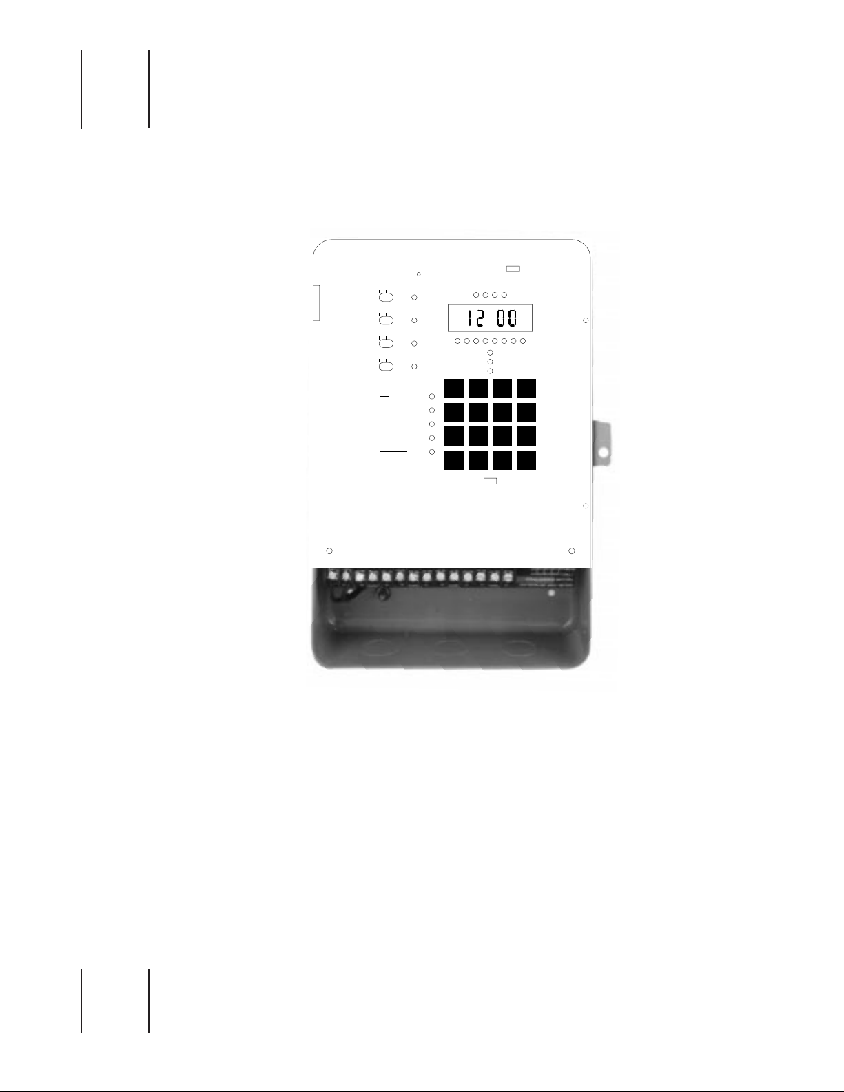
TORK Z400B
OPERATING & INSTALLATION GUIDE
MLI-73(D)
ON AUTO OFF
O
AO
O
AO
O
AO
S
E
T
CHANNEL
YEAR-DATE-TIME
HOLIDAY
SCHEDULE
OVERRIDE
ASTRO
1
2
PM
3
4
SUN2MON3TUE
WED5THU6FRI
SAT8HOL
MODE
SELECT
TORK Z400B
BATTERY
ON
CHANNEL
12
34
SU MO TU WE TH FR SA HO
1BLOCK
2345678
START DATE
ON
END DATE
OFF
DUTY CYCLE
1
4
7
9
ADV0
RUN SET
OFF
DELETE
REVIEW
AM-PM
ENTER
+/–
Page 2

TABLE OF CONTENTS
Page
Keyboard Figure .........................................................................................1
Installation Guide........................................................................................2
Unit Features...............................................................................................3
Key Functions .............................................................................................3
Programming Summary .............................................................................3
Setting the schedules.................................................................................4
Reviewing the settings...............................................................................6
Unit Specifications......................................................................................7
Daylight Saving — Addendum ..................................................................7
Accessories/Application Notes .................................................................8
Scheduling Sheets......................................................................................9
Page 3
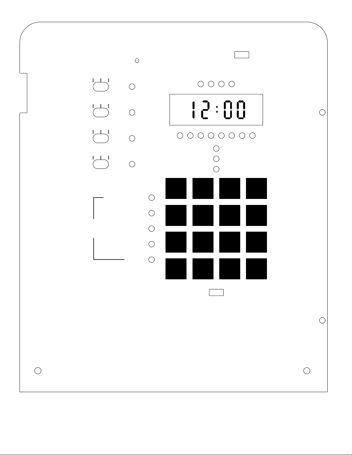
1
BATTERY
ON
OFF
ON AUTO OFF
O
AO
O
AO
O
AO
YEAR-DATE-TIME
S
E
T
CHANNEL
1
2
3
4
HOLIDAY
SCHEDULE
OVERRIDE
CHANNEL
12
PM
SU MO TU WE TH FR SA HO
1BLOCK
2345678
START DATE
END DATE
1
SUN
4
WED
7
SAT
2
MON
5
THU
8
HOL
34
ON
OFF
DUTY CYCLE
3
TUE
6
FRI
9
DELETE
REVIEW
AM-PM
+/–
ASTRO
MODE
SELECT
RUN SET
ADV0
TORK Z400B
ENTER
Page 4

2
1. Make sure unit is grounded (earth ground).
2. If remote overrides are used, make sure these unpowered wires are not run in
the same conduit as the load wires or supply voltage for the unit.
3. Controller must have its own power source, i.e., no outlets or other loads
attached to the same supply source as the controller. Supply wire (hot) must be
run separately from load wire. Do not jump H terminal to load side. Controller
shall not be placed in any other enclosure other than its’ own or warranty will be
void
. Consult factory for outdoor applications.
4. The controller is to be installed where temperatures do not exceed 120°F or
below 32°F. For trouble free operation it should not be exposed to vibration,
dust, corrosive sprays or condensing atmospheric conditions.
5. Control relays are SPDT dry contacts (unpowered) with LED indication when
relay is energized (when common and normally open close).
6. To install unit open front cover to the left and lift off to remove.
7. Make sure to mount unit so that it is at a convenient eye level for viewing
display and operating key board.
8. Place unit at desired location and mark center of key hole on back of enclosure,
using #10 sheet metal screws or other suitable fastening device.
9. Hang enclosure by key hole, locate lower left and right mounting holes and
fasten using 2 additional screws.
10. A. Use knockouts on bottom of enclosure for conduit connections.
B. Do not run any wires from the back of the board.
11. Connect all your load wires and identify them on the supplied schedule sheet.
12. Connect your dedicated 120 VAC line to the left hand side of your terminal
board marked Hot and Neut.
Note. Be sure unit is grounded.
(Convenient
ground terminal is located at the bottom back of the case.)
Do not jump H to any other terminal.
13. Slide Battery Switch to “ON”.
The controller is now ready for scheduling.
Please refer to the users instruction portion of this manual for scheduling
instructions.
Please see additional instructions provided to change from standard to automatic
daylight savings.
For circuits with high electrical noise, utilize the surge suppressors (supplied) across
the switched terminals.
TORK Z400B
INSTALLATION GUIDE
Page 5

3
FEATURES
Four Channels Independent scheduling for each
channel
Duty Cycling: OFF/ON duration 1 to 99 minutes
365 Day Holiday: Scheduling 40 holiday dates and
8 block holidays 1 year in
advance
Remote Overrides: User programmable 1 minute to
16 1/2 hours — displayed in
minutes
Astronomic ON/OFF: Latitude 10° to 60° both
hemispheres, assignable to any
or all channels
256 Set Points: Can be distributed in any number
to any or all channels.
PLEASE READ THE ENTIRE MANUAL BEFORE
PROCEEDING TO SET SCHEDULES. IT IS ADVISABLE
TO USE SCHEDULE SHEETS AT BACK OF MANUAL
BEFORE PROGRAMMING THE Z400B.
KEY FUNCTIONS
BATTERY SWITCH
Slide to “ON” before any scheduling is made.
RUN-SET Slide Switch
Allows the user to choose in the RUN MODE the function
that will be reviewed. In the SET MODE the MODE
SELECT key will allow the user to step through or choose
the functions to be set or changed. i.e. Schedule, Astro, etc.
Appropriate light indicator will allow the user to know what
function is being accessed.
REVIEW
In the RUN MODE, the REVIEW KEY serves to review the
functions available in the unit by stepping through it. In the
SET MODE, the REVIEW KEY serves to display the entries
that may be either left alone or deleted.
DELETE
The SET MODE allows the user to DELETE any entries
while reviewing.
ADVANCE (ADV)
In the SET MODE, the ADV KEY serves as a cursor in
order to move through the information displayed in the front
panel. It is a “STEP” key that allows you to move through
the different data that was entered, such as channels, time
of operation, days of the week, etc.
ENTER
Sets the information being entered into the unit’s memory.
PROGRAMMING SUMMARY
RUN MODE
Displays the current time (AM/PM format only), day of
week, and channel status as per schedule. In this mode,
the user can review all the following menus without
accidental modification:
YEAR DATE TIME
HOLIDAY
SCHEDULE
OVERRIDE
ASTRO
SET MODE
In the SET MODE, flashing LED’s guide user at the
appropriate times, to enter, change, review or delete
data in the five modes listed above. A flashing
channel LED, for example, is asking the user to enter
a new channel # or use the one that is flashing. Also,
a pair of flashing colons are asking for data entry into
display which could be year, date, time, etc. This
feature is the keynote to programming the unit.
Another feature is that any new entry or changes
(note that data entry/change is possible in the SET
MODE) will become active only when the SET/RUN
switch is moved from SET to RUN position. However
any existing entries would continue to be executed
while the SET/RUN switch was in the SET position.
After setting schedules and other data the SET/RUN
switch is moved to the RUN position. The unit will
then execute the true status of the circuits and no
manual ON/OFF is necessary.
The same will happen when the user sets a new
time; the circuit status would be current immediately.
(Look back feature).
Any time a key is pressed an audible signal is
generated (one beep). Every time the entry or
information is entered into the unit’s memory a
double beep signal will be generated. Errors will
generate a multiple-beep signal.
In order for any channel to execute its schedule, the (ONAUTO-OFF) switch must be in the AUTO POSITION.
Z400B
OPERATING GUIDE
Page 6

4
SETTING THE SCHEDULES
Be sure battery switch is ON.
It is advisable to first layout schedules on the schedule
sheets supplied.
IMPORTANT: TO SET DAYLIGHT SAVINGS TIME,
PLEASE SEE ADDENDUM ON PAGE 7 AND EXECUTE
PRIOR TO SETTING SCHEDULES..
If the unit was started for the first time or if memory is
empty, the display shows a flashing SUN 12:00.
If the unit display shows a specific time indicating it retained
old time and data, then proceed with DATE TIME SET or
press the reset button to rid the unit of all data and start
fresh. (See page 1 — clear all memory.) Use a ballpoint
pen or end of a paper clip. Press gently.
Move the SET/RUN switch to the SET position. Be sure
battery switch is on.
YEAR DATE TIME SET
Press MODE SELECT until YEAR DATE TIME LED is lit
constantly (no flashing). The colon will be flashing and 4
zeros (00:00) will be displayed. Sequence of entries should
be: YEAR, MONTH/DATE, TIME. Each one is considered a
partial entry — together, they constitute a complete entry.
YEAR 1 9 8 6 — Press ADVANCE
MONTH/DATE 0 9 1 7 — Press ADVANCE (Correct day
is lit now)
TIME 0 8 1 5 — Press AM or PM, then press
ENTER (you will hear a double beep)
PM is on lower left screen, use AM/PM to change.
When no light is on, it indicates AM time.
YEAR DATE TIME SET LED is flashing again.
NOTES
If an error is made while entering one of the partial entries
(e.g., you keyed in the year 1925 but ADV is yet to be
pressed), just key in the correct year and press ADV.
TIME is the final partial entry in this sequence and the
ENTER key should be pressed. If ADV is pressed, year will
appear again. At this point, year can be changed or, simply
by pressing ADVANCE, MONTH/DATE could be brought on
the display and changed. Similarly by repeatedly pressing
ADVANCE any partial entry could be brought back and
changed. But always press ENTER at the last partial entry.
Time of Day is last partial entry.
HOLIDAY SET
1 Block Holidays
Press the MODE SELECT key until the HOLIDAY
LED is lit constantly (no flashing). The display will
show BLn and the BLOCK 1 LED will be flashing. If
you want to program the block, press ENTER.
The display will show 00:00 and the colon will be
flashing. The BLOCK 1 LED will be lit along with the
START-DATE LED. Use the numbered keys to
program the start date for the block (Month & Day).
Press ADV.
The display will show the same as before except that
the END DATE LED will be lit instead of the START
DATE LED. Program the end date for the block
(Month & Day). Press ENTER.
The same block number will be displayed along with
its flashing LED. Select the next block number to be
programmed and proceed as before. (You can
program up to 8 blocks.)
NOTES: If you do not want to program any more
block holidays, press ADV while the block number is
being displayed and the unit will go to the Single-Day
Holiday scheduling screen. (See Below)
Block dates can not overlap one another. An error
beep will sound. For example, if January 15th - 25th
is one block, you cannot begin another block from
January 20th to February 5th.
2 Single-Day Holidays
Press the MODE SELECT key until the HOLIDAY
LED starts to flash. Press the key once more and the
HOLIDAY LED is constantly lit.
The display will show BLn and the BLOCK NUMBER
1 LED will be flashing.
Press the ADV key to pass block programming and
go to single day holiday programming. The display
will show 00:00 with the colon flashing.
Use the numbered keys to program the date. Press
ENTER. Continue in the same manner to program up
to 40 other dates.
Press the MODE SELECT key when you have
entered the last date.
NOTES: Once you have passed the block holiday
section, you will not be able to program more block
holidays unless you use the MODE SELECT key to
enter the Holiday mode again.
A block holiday with the same start and end date will
be treated as a single day holiday. For example, if
you are out of single day holidays you can use a
block for December 25 - December 25.
All holidays (single and block) are selected when
“HO” is selected in the schedule mode.
Holidays may be entered in any order; unit will place
them chronologically. Up to 40 Holiday dates and 8
blocks may be set a year in advance.
SCHEDULE SET
Press MODE SELECT key to advance to SCHEDULE SET.
LED will be flashing. Press MODE SELECT button again
and the SCHEDULE LED will be lit constantly. The channel
#1 LED will be flashing indicating a channel to be
scheduled must be selected first. The display shows a
default time of 00:00, Monday ON event. The sequence of
entry is:
Press channel # desired (1,2,3, or 4) from main keyboard –
press ADVANCE. Channel LED will be “ON” constantly.
Colons start flashing on indicating time to be entered. Enter
time of first operation and indicate AM/PM. If PM LED in
display is lit, ON or OFF time will be in the PM. Press
Page 7

5
AM/PM key to correct. Press ADVANCE - DAY OF WEEK
LED is flashing, indicating days of the week to be entered.
MON., TUES., WED., etc. Enter days by pressing
appropriate keys. Day LED’s will be flashing. To eliminate a
day, press appropriate day key again.
Press ADVANCE and ON LED is flashing.
When the ON LED is flashing, press ENTER if you want the
load to turn ON at the programmed time. If you want the
load to turn OFF or to DUTY CYCLE, Press ADV until the
OFF or DUTY CYCLE LED, respectively, is flashing.
Press ENTER to store the schedule information.
NOTES
You will hear a double beep when the schedule information
is being stored. If you hear more than 2 beeps, you have
either advanced past ON, OFF or DUTY CYCLE, or the
information you are trying to program is already
programmed.
The schedule information will not be stored when ENTER is
pressed if any LED is flashing except ON, OFF, or DUTY
CYCLE. Press ADV until the desired one of the 3 (ON,
OFF, DUTY CYCLE) is flashing, then Press ENTER.
Monday LED can only be eliminated if another day is
entered.
Schedules are automatically carried over past midnight. No
additional ON entry is necessary at 12:00 AM.
If you press ADVANCE when DUTY CYCLE LED is
flashing, the CHANNEL LED begins to flash again. The
ADVANCE KEY allows you to step through the above
sequence until you are fully satisfied with all the entries
each of which could be changed while the corresponding
LED is flashing (colons for time).
To enter the whole set into the unit’s memory press the
ENTER key at the last entry.
If the event type selected is a DUTY CYCLE, pressing
ENTER key will display 10:10 in the time display window,
the OFF:ON Duty Cycle times. You may change them to
suit your needs and then press ENTER or ADVANCE.
Pressing ENTER will give you a double beep and the unit is
now ready to accept the next schedule entry.
The DAY LED’s could be changed by repeatedly keying in
their corresponding numbers. However, an attempt to turn
off all of the DAY LED’s will give an error beep.
HOLIDAY SCHEDULE SET
To program a holiday schedule, proceed as outlined in the
“SCHEDULE SET” section except select “HO” as the day
selection. That schedule will occur on
all
single day
holidays as well as
all
block holidays.
DUTY CYCLES (Repeated ON/OFF intervals)
To program a duty cycle for a particular channel, slide
RUN/SET switch to SET and proceed as follows:
Press MODE SELECT until SCHEDULE LED is lit
constantly and proceed as per example:
Press Channel #................................2 Press Advance
Enter ON time................08:00 AM/PM Press Advance
Enter days of week.......................................Mon, Tue, Wed
Then press ADVANCE until DUTY CYCLE LED flashes,
press ENTER
Display shows..............................................................10:10
Key in OFF/ON time i.e. OFF 20 ON 40 PRESS ENTER
Then proceed to set your OFF time by following normal
schedule set procedure.
SCHEDULE SET EXAMPLE - ON SETTING
Channel #2 to be turned ON at 7:00 AM MONDAY through
FRIDAY. PRESS MODE SELECT until SCHEDULE LED is
lit constantly. LOAD #1 LED is flashing.
Enter CHANNEL Number 2................ Then Press Advance
Enter TIME......................0 7 0 0 am* Then Press Advance
Enter DAY(s)...Mon, Tue, Wed, Thu, Fri Then Press Advance
Now
ON
LED is flashing Press (ENTER)
Always press ENTER on the last partial entry.
*When setting ON or OFF’s, please note LED in lower left
display indicates PM when lit.
SCHEDULE SET EXAMPLE - OFF SETTING
Channel #2 to be turned OFF at 5:00 PM MONDAY through
FRIDAY. After example above, if load #2 LED is flashing at
this time PRESS ENTER. If not:
Enter CHANNEL Number 2................ Then Press Advance
Enter TIME..............................0 5 0 0 Press AM/PM until
PM is lit. Advance
Enter DAY(s)...Mon, Tue, Wed, Thu, Fri Then Press Advance
Press Advance until “OFF” is flashing, then Press (ENTER)
SETTING DURATION FOR REMOTE TIMED OVERRIDE (Requires external momentary pushbuttons - See
wiring diagram on pg. 8)
1. Press MODE SELECT until OVERRIDE LED is lit
constantly.
2. Channel #1 LED is now flashing.
3. Press channel #1 and press ADVANCE.
4. Colon in display is now flashing 0:00.
5. Enter desired override time in minutes from 1 min. to
999 min. Press ENTER.
6. CHANNEL #2 LED is flashing. At this time, you can
repeat the above instructions for the other channels
by pressing OTHER CHANNEL NUMBERS.
NOTE: If you program all channels with override time and
attempt to enter more, the display will show FULL.
Page 8

6
TO CHANGE OR DELETE OVERRIDES
1. With RUN/SET switch in SET, press mode select until
override LED flashes. Press again and LED is on
constantly.
2. Press REVIEW and Channel #1 LED flashes;
continue to press review until the desired channel
LED flashes.
3. Now press ADV until the colon is flashing. At this
time, enter the override time you desire and press
enter.
4. To delete an entry, press REVIEW until the desired
channel LED is flashing, and press delete.
NOTE:When channel is in override ON Time, it can be
cancelled any time by pressing the button again. The
internal timer will reset. If the override button is pressed
again, override time will start from it’s original amount of
scheduled time.
ASTRONOMIC SET — NORTH OR SOUTH LATITUDES
1. PRESS MODE SELECT UNTIL THE ASTRO LED IS
FLASHING. PRESS AGAIN TO HAVE LED LIT
CONSTANTLY.
2. Channel 1 LED is flashing and display shows Ln:00/
3. The sequence for any Channel to be ASTRO
ON/OFF is:
4. Channel # PRESS CHANNEL NUMBER BUTTON,
THEN ADV (colons flashing now)
5. Press AM/PM to change from northern to southern
latitude and vice versa if needed.
6. Press numbers to desired latitude value of 10° to 60°.
If not known, call local weather bureau.
7. Set to nearest degree including odd numbers, then
press ADV.
8. SUNSET TIME — Display now shows the sunset time
for the date the unit was set. Note that Astronomic
time (sunset or sunrise) are always shown as
STANDARD TIME.Days of week will flash, press day
buttons to eliminate days and/or HOLIDAYS. Press
ADV ONLY.
9. Display now shows :00 with flashing colons and ON
LED is lit.
ASTRONOMIC ON TIME OFFSET
Key in the desired on-time offset 00 to 99 minutes, press
AM/PM for plus or minus offset. Then press ADV. Example:
7:30 PM Astro ON plus 15 min. will be ON at 7:45 PM.
SUNRISE TIME — Display now shows the sunrise time for
the day the unit is set to. PRESS ADV ONLY.
Display shows :00 with flashing colons and OFF LED lit.
ASTRONOMIC OFF TIME OFFSET
1. Press buttons to the desired OFF time OFFSET 00 to
99 minutes, press AM/PM for plus or minus OFFSET.
(see above)
2. Press ENTER to set ASTRO settings to memory.
Now next channel to be programmed begins to flash.
ASTRONOMIC WITH TIME SCHEDULE
If you should decide to have, for example, ASTRO ON Time
and schedule OFF do the following:
1. Follow above ASTRO SETTING for a particular
CHANNEL.
2. Then, when you have done so, go back and follow
SCHEDULE SET procedure to enter an OFF/ON
schedule for that CHANNEL.
3. EXAMPLE
a. ASTRO ON
b. TIME SWITCH OFF
c. TIME SWITCH ON
d. ASTRO OFF
Channel may be SET for Astro ON and Time OFF only.
NOTE: When reviewing Astro settings, sunrise and sunset
are displayed in standard time not daylight savings.
REMEMBER! There is no relation between daylight savings
and sunrise and sunset.
REVIEWING THE SETTINGS
REVIEW IN THE SET MODE
Press the MODE SELECT until the sub mode to be
reviewed has its LED FLASHING.Press REVIEW key and
the first item will be displayed in the REVIEW MODE,
although not indicated by any LED. You are able to review,
change and delete, where needed.
DATE TIME REVIEW
Press REVIEW WHEN DATE TIME LED IS FLASHING.
YEAR is displayed, key in the new year and press ADV or
simply press the review button to check the month/date.
You can repeat this as many times as necessary and then,
if any changes were made, press ENTER when time is
displayed. If no changes were made exit by pressing MODE
SELECT.
IN THE REVIEW MODE OBSERVE THE FOLLOWING:
1. Press ADV after CHANGING a partial entry.
2. Press REVIEW to get to the next partial entry on
display, and press ENTER at the last partial entry to
put into the memory.
3. This remains the same for changes in any of the sub
modes.
While REVIEW/MODIFYING in SCHEDULE SET, if you
want to start reviewing a new channel, press the desired
channel button, the CHANNEL LED will be flashing.
This happens when you press REVIEW while the
SCHEDULE LED is flashing or when the next entry appears
on the screen.
Now press the CHANNEL# you wish to review and press
REVIEW. The first chronological entry in that CHANNEL
schedule will be displayed. Colon in display is now flashing.
If you wish to start reviewing from a certain time onwards,
Page 9

7
key in the time onwards of which you want to review and
press REVIEW or only press REVIEW, then the same
event stays on the display and channel LED starts
flashing.
To make any changes in REVIEW MODIFY, once the
channel indicator is flashing, press ADV until the partial
entry which you want to modify is flashing, i.e. Time,
ON/OFF events, etc. Then modify your entry. Then
advance to the end of a partial entry and press ENTER.
Example: 1987 ADVANCE
0606 ADVANCE
10:00 AM ENTER
NOTE THAT IN BOTH CASES ABOVE, THE ENTRY
WHICH WAS ON THE DISPLAY BEFORE IS NOT
AFFECTED AT ALL.
Reviewing from a different CHANNEL is done the same
way as above for both override and ASTRO feature.
REVIEW IN THE RUN POSITION
When the current time is being displayed, press REVIEW
and the YEAR-DATE-TIME SET LED begins to flash. This
is the PROTECTED REVIEW, although no special LED
indicates this.
ONLY REVIEW OF DATA IS PERMITTED AND NO
CHANGES.
The review process is exactly the same as in the SET
except you cannot press the advance key because no
changes are permitted.
At any time to return to standard run, press the ENTER
KEY.
SPECIFICATIONS
POWER INPUT..........120/240VAC -15% to +10%VAC
50//60 Hz
Power Consumption...12VA Max.
Output Circuits............SPDT Unpowered Contacts
Contact Rating............10 Amps Resistive @ 120/240VAC
10 Amps Resistive @ 30 VDC
1/4 H.P. @ 120VAC
1/3 HP @ 240 VAC
360 Watts Tungsten @ 120VAC
Operating Temp .........0° to +50°C (-35° to +50°C optional)
32°F to 120°F (-30° to +120°F)
(optional)
Battery Backup...........Lithium, 6 months cumulative
Enclosure ...................NEMA 1 Surface Mount
Weight ........................6.5 lbs. (2.95 kg.)
Color...........................Beige
Dimensions.................7 3/4” W x 12” H x 3 1/4” D
ADDENDUM
PLEASE FOLLOW THESE
PROCEDURES TO SET
DAYLIGHT SAVINGS
1. Place run/set switch in the set position.
2. Press MODE SELECT key until HOLIDAY LED
is lit constantly. shows on display.
Block #1 is flashing.
3. Press ADV key and 00:00 will show on display.
4. Key in the start date of DAYLIGHT SAVINGS.
5. Press AM/PM key until
ON
LED is lit . . . then
press ENTER.
6. Colon in display is now flashing.
7. Key in the END of DAYLIGHT SAVINGS . . .
MONTH/DAY.
8. Press AM/PM key. ON LED is now lit.
9. Press AM/PM KEY AGAIN.
OFF
LED is lit.
10. Press ENTER and the unit is now set for
DAYLIGHT SAVING.
11.
PLEASE NOTE:
If no dates are entered into
the unit for DAYLIGHT SAVINGS the unit will
automatically revert to STANDARD TIME.
12. If only one date is entered into the unit, i.e. the
beginning date or end date unit will again revert
back to STANDARD TIME.
REMEMBER TO ENTER BOTH
BEGINNING AND END DATES
TO INSTITUTE AUTOMATIC
DAYLIGHT SAVINGS.
Page 10

Z400B
APPLICATION NOTES
TYPICAL INTERFACE WITH TORK CONTACTORS
Model 5401 - DPST
To control 120 volt circuits where increased voltage and/or
amperage switching is necessary, close or remote from controller.
Can switch up to 40 amps per pole from 120VAC to 480VAC —
one or two circuits simultaneously. Indoor-outdoor enclosure.
TYPICAL INTERFACE WITH
MOMENTARY CONTACT ADAPTER
Model SMC-3D
Momentary contact adapter 120V input maintained contact
converts to SPDT pulsed (2 seconds) circuits. Pulsed switching
circuit will control 24VAC up to 277VAC.
TYPICAL INTERFACE WITH DAY/NIGHT THERMOSTAT
A typical wiring diagram of how to use the Z400B for night set-back
for heating or night set-up for cooling.
Winter Set-back: Set 2-wire night thermostat at 55°F. When
control is “OFF” temperature will not go below 55°.
When control is “ON” (day hours) day thermostat set at 70° to 72°
will override night thermostat.
Summer Set-up: Night thermostat is usually set at 90° to 95°.
When control turns “ON”, day thermostat will override night setting
and cool to (76° to 78°) day setting.
REMOTE TIMED OVERRIDES
8
TORK MODEL Z400B TERMINAL BLOCK
NO C NC
120 VAC
LINE
NEUTRAL
120 VAC COIL
TORK MODELS 5401 & 5441
OR SUITABLE SUBSTITUTE
OPEN
CLOSE
C
Mechanicallyheld contactor
self clearing
Electricallyheld contactor
120/240V LINE
277/480V
40 AMP/POLE
LOAD
SURGE
SUPPRESSOR
120/240
VAC
TORK MODEL Z400B TERMINAL BLOCK
NO C
LINE
NEUTRAL
NC
TORK MODEL Z400B TERMINAL BLOCK
NO C NC
24 Volts
Two Wire
RED
Night
Thermostat
(Time Switch
Circuit OFF)
24 VOLTS
LOW VOLTAGE
CONTROL POWER
FROM HVAC UNIT
POWER
HEAT
COOL
FAN
WHITE
YELLOW
GREEN
Day Thermostat
4-Wire Heat/Cool Thermostat
(Time Switch Circuit ON)
Tork Model SMC-3
ON
LINEOFF
N LINE
24 - 277VAC LINE
REMOTE
MANUAL
STATION
OFF
ON
TO
CONTACTOR
120 VAC
OPEN
CLOSE
COMMON
TORK DIGITAL TERMINAL BLOCK
NO C NC
120V 60HZ
LINE
NEUTRAL
120V
LIGHTING
LOAD
COIL
5401
CONTACTOR
120/240V
277/480V
40 AMPS
PER POLE
TORK MODEL Z400B TERMINAL BLOCK
COMMON
1
234
TORK DIGITAL TERMINAL BLOCK
NO C NC
MOMENTARY PUSHBUTTON
Load to Security
and Alarm System
Load from Security
and Alarm System
Page 11

9
LOAD #
ASTRONOMIC
LATITUDE S M T W T F S H
SUNSET TO SUNRISE SCHEDULE
TIMENO.
SMT
W T F S H ON OFF
SUNSET
OFFSET
SUNRISE
OFFSET
DUTY CYCLE
OFF MIN ON MIN
REMOTE OVERRIDE TIME
MINUTES
Page 12

10
LOAD #
ASTRONOMIC
LATITUDE S M T W T F S H
SUNSET TO SUNRISE SCHEDULE
TIMENO.
SMT
W T F S H ON OFF
SUNSET
OFFSET
SUNRISE
OFFSET
DUTY CYCLE
OFF MIN ON MIN
REMOTE OVERRIDE TIME
MINUTES
Page 13

11
LOAD #
ASTRONOMIC
LATITUDE S M T W T F S H
SUNSET TO SUNRISE SCHEDULE
TIMENO.
SMT
W T F S H ON OFF
SUNSET
OFFSET
SUNRISE
OFFSET
DUTY CYCLE
OFF MIN ON MIN
REMOTE OVERRIDE TIME
MINUTES
Page 14

12
LOAD #
ASTRONOMIC
LATITUDE S M T W T F S H
SUNSET TO SUNRISE SCHEDULE
TIMENO.
SMT
W T F S H ON OFF
SUNSET
OFFSET
SUNRISE
OFFSET
DUTY CYCLE
OFF MIN ON MIN
REMOTE OVERRIDE TIME
MINUTES
Page 15

13
LOAD #
TIMENO.
SMT
DESCRIPTION
DUTY CYCLE
W T F S H ON OFF
OFF MIN ON MIN
REMOTE OVERRIDE TIME
MINUTES
Page 16

14
LOAD #
TIMENO.
SMT
DESCRIPTION
DUTY CYCLE
W T F S H ON OFF
OFF MIN ON MIN
REMOTE OVERRIDE TIME
MINUTES
Page 17

15
LOAD #
TIMENO.
SMT
DESCRIPTION
DUTY CYCLE
W T F S H ON OFF
OFF MIN ON MIN
REMOTE OVERRIDE TIME
MINUTES
Page 18

16
LOAD #
TIMENO.
SMT
DESCRIPTION
DUTY CYCLE
W T F S H ON OFF
OFF MIN ON MIN
REMOTE OVERRIDE TIME
MINUTES
Page 19

LIMITED WARRANTY — TORK, INC. warrants all Controls manufactured
by TORK to be free of defects in material and workmanship under normal
use for a period of one (1) year from date of manufacture. TORK reserves
the right to change designs or materials without prior notice as it may deem
necessary. Liability under this written warranty and under implied
warranties is limited to the repair or replacement. without charge, at
TORK’s option, of any defective Control or part thereof for the original user,
and only if the defective Control or part is returned to TORK, at 1 Grove
Street, Mount Vernon, New York 10550, or to an authorized servicing
station at the address indicated on TORK’S catalog sheets, freight prepaid
within such one (1) year period.
TORK’s liability shall in no event exceed the purchase price of the Control
paid by the original user. This warranty is void if the Control has been
improperly installed or altered or damaged through misuse, or by accident,
neglect, misapplication, fire, flood or Acts of God. TORK assumes no
responsibility for any damages to people, property, apparatus or otherwise
resulting from improper installation or maintenance of its Control.
The foregoing warranty IS IN LIEU OF ALL OTHER EXPRESS
WARRANTIES. ALL IMPLIED WARRANTIES, INCLUDING DESCRIPTION, MERCHANTABILITY AND FITNESS FOR PURPOSE, ARE
LIMITED TO THE TERM OF THIS WRITTEN WARRANTY. IN NO EVENT
SHALL TORK BE LIABLE FOR INCIDENTAL AND CONSEQUENTIAL
DAMAGES. Some states do not allow limitations on how long an implied
warranty lasts, so the above limitation may not apply to you. Some states
do not allow the exclusion or limitation of incidental or consequential
damages, so the above limitation or exclusion may not apply to you. This
written warranty gives you specific legal rights, and you may also have
other rights which vary from state to state.
TORK Z400B
LIMITED WARRANTY
TORK
®
1 GROVE STREET, MT. VERNON, NY 10550 TEL: 914-664-3542
FAX: 914-664-5052
Ptd. in U.S.A.
 Loading...