

Page 1
NSi Industries, LLC • USA • 877.230.7874 • www.nsiindustries.com
Page 2
MODEL#: TU40
FEATURES:
•Real-Time Clock Face with
OFF/AUTO/ON Override Switch
•Captive Trippers
•15 Minute Intervals
•NEMA 3R Plastic Indoor/Outdoor
Enclosure
•Green LED Indicates power
•Red LED indicates load status
•40 AMP DPDT Contacts
•8-18 AWG Screw Terminals
OUTPUT:
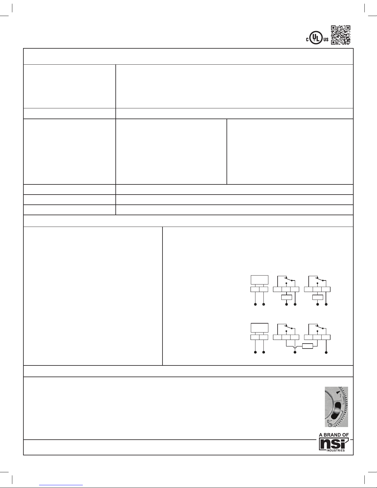
DPDT, Dry Contacts (Unpowered) all in one may also be used for SPST, SPDT, DPST
CONTACT RATINGS: NO CONTACTS:
40 AMPS RESISTIVE @ 120-277 VAC 60Hz
30 AMPS INDUCTIVE @ 120-277 VAC
1HP, 30FLA, 90LRA @ 120 VAC
2HP, 20FLA, 60 LRA @ 240 VAC
30 AMPS BALLAST @ 120 VAC
20 AMPS BALLAST @ 277 VAC
15 AMPS TUNGSTEN @ 120 VAC
20 AMPS RESISTIVE @ 28 VDC
720 VA PILOT DUTY @ 120-240 VAC
30 AMPS MAX ABOVE 104°F
NC CONTACTS:
30 AMPS RESISTIVE @ 120-277 VAC 60Hz
15 AMPS INDUCTIVE @ 120-277 VAC
1/4HP, 12FLA, 30 LRA @ 120 VAC
1/2HP, 12FLA, 33 LRA @ 250 VAC
10 AMPS BALLAST @ 120-277 VAC
290 VA PILOT DUTY @ 120VAC
360 VA PILOT DUTY @ 240 VAC
OPERATING TEMP:
-31°F to 116°F (-35°C to +47°C) Relative Humidity is 10% to 95%
TIMER SUPPLY:
120/208-240/277VAC, 60Hz Detects voltage automatically (NO DIP SWITCH SETTING REQUIRED)
POWER CONSUMPTION:
6VA Max @ 120VAC
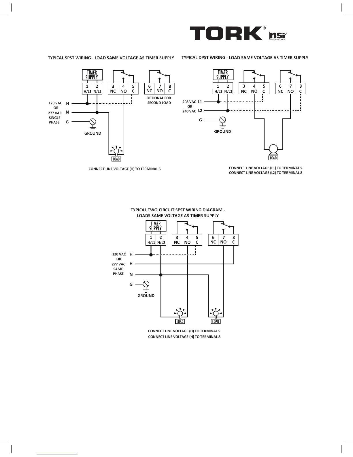
INSTALLATION & WIRING DIAGRAMS
UNIT IS TO BE INSTALLED BY A
LICENSED ELECTRICIAN
1. Mount the enclosure at eye level using screws or
other suitable fastening device. Bring supply and
load wires in through bottom or side knockouts.
2. Wire as per typical wiring diagram below, and
follow all local and NEC codes.
3. To ensure proper connection to the terminal
block, turn the screw fully counterclockwise
before inserting wires. Firmly fasten the screw
terminal
SETTING ON/OFF TIMES
1. The timer has 96 tabs which can turn loads ON or OFF every 15 minutes. Push tabs outward to turn the load ON,
and pull them inwards to turn the load OFF for the desired ON and OFF durations.
2. Rotate dial clockwise to set the time. Align time with arrow. DO NOT ATTEMPT TO SET THE TIME BY USING
THE MINUTE HAND IN THE CENTER OF THE DIAL.
3. Automatic operation: To execute the programmed schedule, set the selector switch to the center position.
(Shown by clock symbol)
4. MANUAL OVERRIDE: Set the switch to the “I” position to turn the load permanently ON.
Set the switch to the “0” position to turn the load permanently OFF.
877.230.7874 • www.nsiindustries.com
UNIVERSAL MULTI-VOLTAGE
ELECTROMECHANICAL TIME SWITCH
Use copper wire AWG 8-18 suitable for 90°C. WIRING TO COMPLY WITH ALL LOCAL AND NATIONAL ELECTRICAL CODES. Bonding between conduit connection is not automatic and must
be provided as part of the installation. THE ENCLOSURE MUST BE PROPERLY GROUNDED.
Minimum 10.6 lb. in. torque required at the terminals to ensure proper connections. Strip the
supply and load wires to 1/2”.
LI-831(C)
PATENT PENDING
N
LN
NC NO C
LN
NC NO C
LN
Typical Wiring Diagram, 120 VAC Application
HN
L1 L2
NC NO C
L1
NC NO C
L2
TIMER
SUPPLY
TIMER
SUPPLY
LOAD LOAD
LOAD
H
Typical Wiring Diagram, 208-240 VAC Application
Typical Wiring Diagram, 120/277VAC Application
DTU40
Page 3

MODÈLE : TU40
CARACTÉRISTIQUES :
• Dessus affichant l’heure courante muni
d’un interrupteur prioritaire avec commandes d’arrêt, de fonctionnement
automatique et de mise en marche
• Déclencheurs captifs
• Intervalles de 15 minutes
• BOÎTIER NEMA 3R EN Plastique pour
l’intérieur et l’extérieur
• Voyant à DEL vert indique que l’appareil est alimenté
• Voyant à DEL rouge indique que l’appareil est en état
de charge
• Contacts bipolaires bidirectionnels de 40 A
• Bornes à vis de calibre 8-18 AWG
SORTIE :
Les contacts secs (qui ne sont pas sous tension) et bipolaires bidirectionnels tout-en-un peuvent également être utilisés de
façon unipolaire unidirectionnelle, unipolaire bidirectionnelle et bipolaire unidirectionnelle
CAPACITÉ DES CONTACTS :
CONTACTS NORMALEMENT OUVERTS :
40 A RÉSISTIF À 120-277 V c.a. 60Hz
30 A INDUCTIF À 120-277 V c.a.
1 HP, INTENSITÉ MAXIMALE DE 30, 90 LRA À 120 V c.a.
2 HP, INTENSITÉ MAXIMALE DE 20, 60 LRA À 240 V c.a.
BALLAST DE 30 A À 120 V c.a.
BALLAST DE 20 A À 277 V c.a.
15 A TUNGSTÈNE À 120 V c.a.
20 A RÉSISTIF À 28 V.C.C.
720 VA RÉGIME DE FONCTIONNEMENT
ASSERVI À 120-240 V c.a.
30 A MAX. AU-DESSUS DE 40 °C
CONTACTS NORMALEMENT FERMÉS :
30 A RÉSISTIF À 120-277 V c.a. 60Hz
15 A INDUCTIF À 120-277 V c.a.
1/4 HP, INTENSITÉ MAXIMALE DE 12, 30 LRA À 120 V c.a.
1/2 HP, INTENSITÉ MAXIMALE DE 12, 33 LRA À 250 V c.a.
BALLAST DE 10 A À 120-277 V c.a.
290 VA RÉGIME DE FONCTIONNEMENT ASSERVI À 120 V c.a.
360 VA RÉGIME DE FONCTIONNEMENT ASSERVI À 240 V c.a.
TEMPÉRATURE DE
FONCTIONNEMENT :
-35 °C à 47 °C (-31 °F à 116 °F) et lorsque l’humidité relative est de 10 % à 95 %
ALIMENTATION DE
LA MINUTERIE :
120/208-240/277 V c.a., 60 Hz, détecte la tension automatiquement
(aucun réglage du commutateur DIP nécessaire)
CONSOMMATION :
6 VA MAX. À 120 V c.a.
SCHÉMAS DES FILS ET DE L’INSTALLATION
CET APPAREIL DOIT ÊTRE INSTALLÉ PAR
UN ÉLECTRICIEN QUALIFIÉ
1. Installez le boîtier à hauteur des yeux à l’aide de
vis ou d’autres éléments de fixation appropriés.
Insérez les fils d’alimentation et de charge dans
les entrées défonçables situées sur les côtés et le
dessous du boîtier.
2. Câblez selon le schéma de câblage classique
ci-dessous et suivez tous les codes d’électricité de
votre région et le Code national de l’électricité.
3. Afin d’effectuer une connexion à la borne de façon appropriée, tournez la vis dans le sens contraire des aiguilles d’une montre avant d’insérer
les fils. Serrez fermement la borne à vis.
RÉGLAGE DES HEURES DE MISE EN MARCHE ET D’ARRÊT :
1. La minuterie comprend 96 languettes qui permettent de mettre en marche ou d’éteindre la charge toutes les 15 minutes. Pour
déterminer le temps de mise en marche et d’arrêt, poussez les languettes vers l’extérieur pour mettre en marche et tirez-les vers
l’intérieur pour éteindre.
2. Tournez le cadran dans le sens des aiguilles d’une montre pour régler l’heure. Alignez l’heure avec la flèche.
N’ESSAYEZ PAS DE RÉGLER L’HEURE À L’AIDE DE L’AIGUILLE DES MINUTES SITUÉE AU CENTRE DU CADRAN.
3. Fonctionnement automatique : Afin d’activer l’horaire programmé, placez le sélecteur à la position centrale.
(Tel qu’il est illustré par le symbole de l’horloge)
4. PASSER OUTRE MANUELLEMENT : Placez le sélecteur à la position « I » afin de permettre l’alimentation de façon
permanente. Placez le sélecteur à la position « 0 » afin de couper l’alimentation de façon permanente.
877.230.7874 • www.nsiindustries.com
MINUTERIE ÉLECTROMÉCANIQUE À
TENSION RÉGLABLE UNIVERSELLE
Utilisez des fils en cuivre de calibre AWG 8-18 pouvant résister à une température de 90 °C. RESPECTEZ LE CODE NATIONAL DE
L’ÉLECTRICITÉ ET TOUS LES CODES LOCAUX QUI PORTENT SUR LE CÂBLAGE. La liaison électrique entre les raccords de conduit n’est pas
automatique et doit être comprise avec l’installation. LE BOÎTIER DOIT ÊTRE MIS À LA TERRE DE FAÇON APPROPRIÉE. Un couple d’au
moins 1,22 kilogramme-force/mètre aux bornes est nécessaire pour assurer une connexion appropriée. Dénudez de 1,27 cm les fils
d’alimentation et de charge.
LI-831(C)
BREVET EN INSTANCE
N
LN
NC NO C
LN
NC NO C
LN
HN
L1 L2
NC NO C
L1
NC NO C
L2
TIMER
SUPPLY
TIMER
SUPPLY
LOAD LOAD
LOAD
H
DTU40 french
Schéma de câblage classique, utilisation de 120/277 V c.a.
Alimentation
de la minuterie
CHARGE
CHARGE
Alimentation
de la minuterie
CHARGE
Schéma de câblage classique, utilisation de 120/277 V c.a.
Page 4

MODELO#: TU40
CARACTERÍSTICAS:
•Parte frontal del reloj con la hora real,
con interruptor de anulación de APAGADO/AUTOMÁTICO/ENCENDIDO
•Disyuntores cautivos
•Intervalos de 15 minutos
•Protección de plástico NEMA 3R para interiores
y exteriores
•La luz LED verde indica si está encendido
•La luz LED roja indica que se está cargando
•Contactos DPDT de 40 AMP
•Terminales de tornillos de 8 a 18 AWG
SALIDA:
Los contactos en seco DPDT (sin corriente) todo en uno también pueden utilizarse para SPST, SPDT y DPST
CLASIFICACIONES DEL
CONTACTO:
CONTACTOS NO:
RESISTIVO DE 40 AMPS @ 120-277 VCA 60Hz
INDUCTIVO DE 30 AMPS @ 120-277 VCA
1 HP, 30 FLA, 90 LRA @ 120 VCA
2 HP, 20 FLA, 60 LRA @ 240 VCA
BALASTRO DE 30 AMPS @ 120 VCA
BALASTRO DE 20 AMPS @ 277 VCA
TUNGSTENO DE 15 AMPS @ 120 VCA
RESISTIVO DE 20 AMPS @ 28 VCC
CAPACIDAD DETERMINADA EXPERIMENTALMENTE
DE 720 VA @ 120-240 VCA
30 AMPS MÁX. SOBRE 40 ºC
CONTACTOS NC:
RESISTIVO DE 30 AMPS @ 120-277 VCA 60Hz
INDUCTIVO DE 15 AMPS @ 120-277 VCA
1/4 HP, 12 FLA, 30 LRA @ 120 VCA
1/2 HP, 12 FLA, 33 LRA @ 250 VCA
BALASTRO DE 10 AMPS @ 120-277 VCA
CAPACIDAD DETERMINADA EXPERIMENTALMENTE
DE 290 VA @ 120 VCA
CAPACIDAD DETERMINADA EXPERIMENTALMENTE
DE 360 VA @ 240 VC
TEMPERATURA DE
FUNCIONAMIENTO:
-31°F to 116°F (-35°C to +47°C) con una humedad relativa de 10% a 95%
SUMINISTRO DEL
TEMPORIZADOR:
120/208-240/277 VCA, 60Hz, Detecta el voltaje automáticamente (SIN NECESIDAD DE CONFIGURAR EL INTERRUPTOR MAGNÉTICO)
CONSUMO DE ENERGÍA:
6 VA Máx. @ 120 VCA
INSTALACIÓN Y DIAGRAMAS DEL CABLEADO
LAS UNIDADES DEBE SER INSTALADAS
POR UN ELECTRICISTA CALIFICADO
1. Monte la caja a la altura de los ojos usando
tornillos u otros dispositivos de fijación adecuados. Coloque los conductores de carga
y suministro en los orificios semiperforados
inferiores o laterales.
2. Realice el cableado según el diagrama del
cableado típico que aparece a continuación,
y siga todos los códigos locales y el Código
nacional de electricidad.
3. Para asegurar una conexión adecuada al
bloque de terminales, gire el tornillo en dirección contraria a las manecillas del reloj por
completo antes de insertar los cables. Apriete
bien el terminal del tornillo
CONFIGURACIÓN DE LA HORA DE ENCENDIDO/APAGADO:
1. El temporizador tiene 96 botones que pueden ENCENDER o APAGAR las cargas cada 15 minutos. Presione los botones
hacia afuera para encender la carga y hacia adentro para apagarla para fijar las duraciones de ENCENDIDO y APAGADO
deseadas.
2. Gire el selector en la dirección de las manecillas del reloj para fijar la hora. Alinee la hora con la flecha.
NO INTENTE CONFIGURAR LA HORA UTILIZANDO EL MINUTERO AL CENTRO DE LA PERILLA.
3. Funcionamiento automático: Para ejecutar el programa establecido, coloque el interruptor selector en
la posición central. (Lo indica el símbolo del reloj)
4. ANULACIÓN MANUAL: Coloque el interruptor en la posición “I” para ENCENDER la carga de forma
permanente. Coloque el interruptor en la posición “O” para APAGAR la carga de forma permanente.
877.230.7874 • www.nsiindustries.com
INTERRUPTOR DE TIEMPO
ELECTROMECÁNICO DE VOLTAJE
MÚLTIPLE UNIVERSAL
Use cable de cobre AWG 8-16 adecuado para 90 ˚C. EL CABLEADO DEBE CUMPLIR CON TODOS LOS CÓDIGOS ELÉCTRICOS
LOCALES Y NACIONALES. La unión entre las conexiones del conducto no es automática y se debe proporcionar como parte
de la instalación. LA CAJA DE PROTECCIÓN DEBE TENER UNA PUESTA A TIERRA ADECUADA. Se requiere un torque mínimo
de 1,22 kgf-m en los terminales para asegurarse de que las conexiones sean las adecuadas. Pele 1,27 cm de los cables de
suministro y de carga.
LI-831(C)
PATENTE EN TRÁMITE
N
LN
NC NO C
LN
NC NO C
LN
HN
L1 L2
NC NO C
L1
NC NO C
L2
TIMER
SUPPLY
TIMER
SUPPLY
LOAD LOAD
LOAD
H
DTU40 french
N
LN
NC NO C
LN
NC NO C
LN
Typical Wiring Diagram, 120 VAC Application
HN
L1 L2
NC NO C
L1
NC NO C
L2
TIMER
SUPPLY
TIMER
SUPPLY
LOAD LOAD
LOAD
H
DTU40 Spanish
Schéma de câblage classique, utilisation de 120/277 V c.a.
Alimentation
de la minuterie
CHARGE
CHARGE
Alimentation
de la minuterie
CHARGE
Diagrama de cableado típico, aplicación a 120/277 VCA
Diagrama de cableado típico, aplicación a 208/240 VCA
CARGA CARGA
CARGA
temporizador
Suministro del
temporizador
Suministro del
Schéma de câblage classique, utilisation de 120/277 V c.a.
 Loading...