

Page 1
®
PERCENTAGE TIMER
MODEL#: EJWT
The control will cycle loads on/off based on the setting of the control knobs as long as input power is supplied. The control will start with the on time cycle after initial power is applied
to the control. The unit is simple to set consisting of only two dials: one CYCLE TIME dial to set time durations and one % ON dial to set the percentage of ON time for the selected
duration.
Total cycle duration can be set from 15 seconds minimum to 24 hours maximum, The % ON setting for each cycle duration is independently adjustable from 0% (continuous OFF) to
100% (continuous ON) in 32 increments
POWER
REQUIREMENTS:
ENVIRONMENTAL:
CONTACT
RATING:
ENCLOSURE:
MOUNTING:
DIALS:
MAINTENANCE:
Inputs: 120 and 240 VAC (+10% -15% at 60 Hz)
Outputs: SPDT relay with 20 Amp N.O. and 10 Amp N.C. general purpose at 120,240 VAC; N.O. 1 HP at 120 VAC, 2HP at 240 VAC
Operating Temperature Range: 32°F to 122°F (0°C to 50°C).
Operating Humidity Range: Relative humidity up to 100%
Water Resistance: The control will be capable of direct low-pressure water wash down according to NEMA 4X specification.
VOLTAGE LOAD TYPE N.O. CONTACTS N.C. CONTACTS
120-240 VAC Resistive 20 A 10 A
120-240 VAC General Purpose 20 A 10 A
120 VAC Motor 1 HP ¼ HP
208-240 VAC Motor 2 HP ½ HP
120-240 VAC Pilot Duty 470 VA 275 VA
NEMA type 4X (indoor use only) enclosure standard (EJWT). Watertight cover with gasket is flame retardant UV stabilized and non-metallic. In grey.
Control is compatible for mounting to Tork’s NEMA 4X nonmetallic enclosure
Sealed from external access
Cleaning: Use only mild detergent and water
to clean the enclosure
Disconnect power at main panel prior to installing
or servicing this lighting control or the equipment connected to it.
! CAUTION !
RISK OF ELECTRIC SHOCK
INSTALLATION & WIRING INSTRUCTIONS
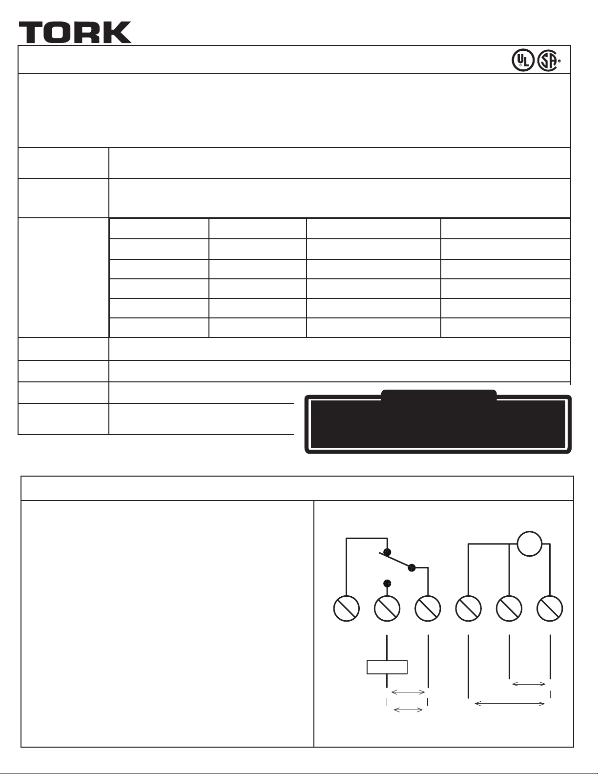
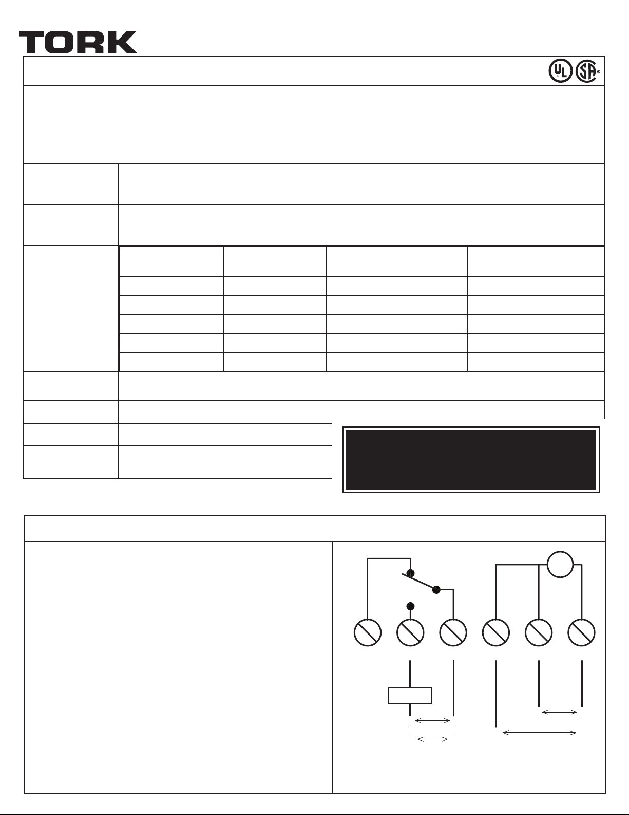
Note:Wiring connections are made to a six-position terminal block. All
terminals accept AWG #18 to AWG #12 wire.
1. Turn off all power to the timer circuit at the distribution panel before
beginning the installation.
2. The EJWT box contains knockouts on two sides. Determine the most
convenient way to mount the box to the conduit and remove the
appropriate knockout. To secure the box to a fixed location, use at
least two of the four box mounting knockouts located on the back of
the box.
3. Wire timer for either 120 VAC or 240 VAC as shown by the wiring
diagram. Wire the load to the timer as shown in the wiring diagram,
noting the contact load type and ratings shown.
4. Securely attach the timer to Tork’s NEMA 4X (for indoor use only)
non-metallic enclosure with the included screws.
SPDT
NC NO COM 240V/L1 120V NEUT/L2
LOAD
120V
LN
L1L2
FOR 240V
L1
FOR 240V
APPLY ONLY ONE VOLTAGE
T
120V
N
L
L2
Page 2

ON/OFF TIME SETTING INSTRUCTIONS
FOR LOADS USING NORMALLY OPEN (NO) RELAY CONTACTS
To set the ON time:
1. Select the total cycle time between 15 seconds and 24 hours, using the dial on the left.
2. Set ON time duration using the right dial (% ON). The ON time duration is a percentage of the total cycle time chosen in the previous step. Set percentage to
desired length of time that the load (fan, light, etc,) is to be turned on. The control will turn the load on for the defined % and then off until the total cycle
time is reached, then the process is repeated until power is interrupted or the program is changed. For example to cycle a load on for 30 seconds and off for
4 minutes and 30 seconds, one would choose a five minute cycle time with the left dial and a 10% cycle time with the right dial. See Table 2 for all possible
ON/OFF time settings.
3. The green ON LED will blink once a second when the load circuit is ON and has a timed duration. The red OFF LED will blink once a second when the load
circuit is OFF and has a timed duration.
To set for CONTINOUS ON:
To set the timer for a CONTINUOUS ON condition, align the pointer on the % ON dial to be 100% ON position (approximately 12:00 o’clock position). The
green ON LED will illuminate steadily when the timer is set for a continuous ON condition.
To set for CONTINOUS OFF:
To set the timer for a CONTINUOUS OFF condition, align the pointer on the % ON dial to be 0% OFF position (approximately 12:00 o’clock position.) This
position takes precedence over all other active timing or continuous settings of the timer. The red OFF LED will illuminate steadily when the timer is set for a
continuous OFF conditions.
FOR LOADS USING NORMALLY CLOSED (NC) RELAY CONTACT:
The normally closed relay contact is provided to enable a secondary load to be switched at opposite time intervals of the main load (the load controlled by
the normally open contact.) When the load that is connected to the normally open relay contact is ON, the load connected to the normally closed contact is
OFF. When the load that is connected to the normally open relay contact is OFF, the load that is connected to the normally closed contact is ON.
PROGRAMMING & OPERATING THE TIMER
OPERATING PARAMETERS
• The control will repeat cycle within 1% of timing range.
• The control will automatically reset after a 1 second power interruption. The control will resume the cycle starting with the ON time after power has been
restored.
ONE YEAR LIMITED WARRANTY: If this product fails because of a manufacturing defect within one year after purchase, we will, at our option, either repair or replace it at no charge.
Our warranty does not cover damage caused by accident, abuse or misuse. We assume no further liability with respect to the sale or use of this product. THIS WARRANTY IS IN LIEU
OF ALL OTHER WARRANTIES, EXPRESSED OR IMPLIED, INCLUDING THE WARRANTY OF MERCHANTABILITY. We make no warranty with respect to the fitness of any goods for the
users particular appplication. This warranty gives you specific legal rights, and you also may have other rights which vary from state to state.
MLI-194(B) NSI INDUSTRIES, LLC • 888.500.4598 • www.nsiindutries.com
A DIVISION OF
NSi INDUSTRIES, LLC
Page 3
®
MINUTERIE à POURCENTAGE
MODÈLE : EJWT
La commande mettra les charges à ON (marche) et à OFF (arrêt) en fonction du réglage des boutons de commande, et ce, aussi longtemps qu’il y aura un signal d’entrée. La commande lancera le cycle de mise en marche après avoir reçu une alimentation initiale. L’appareil est simple à régler, puisqu’il ne comporte que deux cadrans : un cadran CYCLE TIME
(durée du cycle) servant à établir la durée du cycle et un cadran % ON (taux de fonctionnement) servant à indiquer le taux de fonctionnement de la charge pendant ce cycle.
La durée totale du cycle peut se situer entre 15 secondes (minimum) et 24 heures (maximum). Le taux de fonctionnement associé à chaque cycle peut être réglé de manière indépendante et aller de 0 % (arrêt en continu) à 100 % (fonctionnement en continu). Ce réglage compte 32 échelons.
EXIGENCES
D’ALIMENTATION :
ENVIRONNEMENT :
Signaux d’entrée : 120 et 240 V c.a. (+10 % -15 % à 60 Hz)
Signaux de sortie : Contacts de relais unipolaires bidirectionnels à 20 A (normalement ouverts) et 10 A (normalement fermés), usage général : 120 et 240 V
c.a.; contact normalement ouvert : 1 HP à 120 V c.a., 2 HP à 240 V c.a.
Gamme des températures de fonctionnement : de 0 ºC à 50 ºC (32 ºF à 122 ºF).
Gamme des taux d’humidité relative de fonctionnement : jusqu’à 100 %
Résistance à l’eau : La commande peut supporter un faible débit d’eau direct conformément à la norme NEMA 4X.
TENSION TYPE DE CHARGE
120-240 V c.a. Résistive 20 A 10 A
CAPACITÉ DES
120-240 V c.a. Usage général 20 A 10 A
CONTACTS :
120 V c.a. Moteur 1 HP ¼ HP
208-240 V c.a. Moteur 2 HP ½ HP
120-240 V c.a. Commande pilote 470 VA 275 VA
BOÎTIER :
ASSEMBLAGE :
CADRANS :
ENTRETIEN :
NEMA 4x (pour usage à l’intérieur seulement). Le couvercle doté d’un joint d’étanchéité est à l’épreuve du feu,
stabilisé aux rayons UV et non métallique. Gris.
La commande peut être installée sur le boîtier non métallique NEMA 4X de Tork.
Accès externe impossible
Nettoyage : Nettoyez le boîtier avec un détergent doux
et de l’eau seulement.
INSTALLATION ET CÂBLAGE
Remarque : Les connexions du câblage sont effectuées à l’aide
d’une borne à six positions. Toutes les bornes sont conçues pour les fils de calibre
AWG 18 à AWG 12.
CONTACTS NORMALEMENT
OUVERTS
MISE EN GARDE :
Un seul sectionneur peut ne pas être suffisant pour mettre l’équipement hors tension avant
l’entretien. Coupez le courant à partir du tableau de distribution principal avant d’installer
ou de réparer cet appareil de commande de l’éclairage ou tout équipement y étant branché.
REMETTEZ L’ISOLATEUR EN PLACE UNE FOIS LE CÂBLAGE EFFECTUÉ.
SPDT
SPDT
NORMALEMENT FERMÉS
RISQUE DE CHOC ÉLECTRIQUE
CONTACTS
T
1. Avant de commencer l’installation, coupez complètement l’alimentation du
circuit de la minuterie à partir du panneau de distribution.
2. Des pastilles défonçables se trouvent des deux côtés du boîtier de la minuterie EJWT. Déterminez la manière la plus pratique d’installer le boîtier
sur le conduit, puis retirez la pastille défonçable appropriée. Pour fixer
le boîtier à un emplacement précis, utilisez au moins deux des quatre
pastilles défonçables qui se trouvent à l’arrière.
3. Procédez au câblage de la minuterie (pour 120 ou 240 V c.a.) conformément au schéma de câblage. Câblez le circuit de charge et la minuterie
conformément au schéma de câblage, en tenant compte du type de charge
et des valeurs nominales.
4. Fixez solidement la minuterie sur le boîtier non métallique NEMA 4X de
Tork (pour usage à l’intérieur seulement) à l’aide des vis incluses.
NC NO COM
NC NO COM 240V/L1 120V NEUT/L2
LOAD
CHARGE
120V
120V
LN
L1L2
POUR 240V
FOR 240V
240V/L1
L1
APPLY ONLY ONE VOLTAGE
120V
FOR 240V
POUR 240V
APPLIQUER UNE SEULE TENSION
NEUTRE/L2
120V
120V
N
L
L2
Page 4

INSTRUCTIONS POUR LE RÉGLAGE DES
PÉRIODES DE MISE EN MARCHE ET D’ARRÊT
POUR LES CHARGES UTILISANT DES CONTACTS DE RELAIS NORMALEMENT OUVERTS
Réglage de la période de MISE EN MARCHE :
1. Déterminez la durée totale du cycle (entre 15 secondes et 24 heures) à l’aide du cadran de gauche.
2. Réglez le taux de fonctionnement (% ON) à l’aide du cadran de droite. Ce taux correspond à un pourcentage de la durée totale du cycle établie à l’étape
précédente. Indiquez le pourcentage correspondant à la période de temps pendant laquelle la charge (ventilateur, luminaire, etc.) doit être en marche. La
minuterie mettra la charge sous tension pendant le pourcentage de temps établi, puis l’éteindra pendant le reste de la durée totale du cycle. Ces cycles se
répéteront jusqu’à ce que l’alimentation soit interrompue ou que le programme soit modifié. Par exemple, pour qu’une charge soit mise en marche pendant
30 secondes, puis éteinte pendant 4 minutes 30 secondes, on fixera la durée totale du cycle à 5 minutes à l’aide du cadran de gauche et le taux de fonctionnement à 10 % à l’aide du cadran de droite. Veuillez consulter le tableau 2 pour connaître tous les réglages possibles pour le temps de fonctionnement
et d’arrêt.
3. Le voyant à DEL vert ON (marche) clignote à une fréquence de 1 Hz lorsque le circuit de charge est à ON et qu’une durée minutée y est associée. Le voyant
à DEL rouge OFF (arrêt) clignote à une fréquence de 1 Hz lorsque le circuit de charge est à OFF et qu’une durée minutée y est associée.
Réglage du mode de FONCTIONNEMENT EN CONTINU :
Pour mettre la minuterie en mode de fonctionnement en continu, mettez l’aiguille du cadran % ON (taux de fonctionnement) en position 100% ON
(fonctionnement à 100 % du temps), soit environ à l’endroit où se trouve le 12 sur une horloge. Le voyant à DEL vert ON (marche) brille sans interruption
lorsque la minuterie est en mode de fonctionnement en continu.
Réglage du mode d’ARRÊT EN CONTINU :
Pour mettre la minuterie en mode CONTINUOUS OFF (arrêt en continu), mettez l’aiguille du cadran % ON (taux de fonctionnement) en position 100% OFF
(arrêt à 100 % du temps), soit environ à l’endroit où se trouve le 12 sur une horloge. Ce réglage a préséance sur tous les autres minutages en cours et sur
les modes continus de la minuterie. Le voyant à DEL rouge OFF (arrêt) brille sans interruption lorsque la minuterie est en mode d’arrêt en continu.
POUR LES CHARGES UTILISANT UN CONTACT DE RELAIS NORMALEMENT FERMÉ
Le contact de relais normalement fermé sert à mettre en service une charge secondaire qui sera activée à des intervalles de temps opposés à ceux de la
charge principale (celle qui est activée par le contact de relais normalement ouvert). Lorsque la charge raccordée au contact de relais normalement ouvert
est à ON (marche), celle qui est branchée sur le contact de relais normalement fermé est à OFF (arrêt). Lorsque la charge raccordée au contact de relais
normalement ouvert est à OFF (arrêt), celle qui est branchée sur le contact de relais normalement fermé est à ON (marche).
PROGRAMMATION ET FONCTIONNEMENT DE LA MINUTERIE
PARAMÈTRES OPÉRATIONNELS
• La commande recommencera le cycle en tolérant un écart de 1 % au plus par rapport à l’intervalle de temps.
• La commande se réinitialisera automatiquement après une coupure de courant de 1 seconde. Elle relancera le cycle à partir de la période de marche établie
une fois que le courant sera rétabli.
GARANTIE LIMITÉE DE UN AN : Si ce produit s’avère défaillant en raison d’un défaut de fabrication dans une période de un an suivant son achat, nous choisirons, à notre discrétion, de le réparer ou de le remplacer sans frais. Notre garantie ne couvre pas les dommages causés par un accident ou un usage abusif ou inapproprié. Nous déclinons toute autre
responsabilité en ce qui a trait à la vente ou à l’utilisation de ce produit. CETTE GARANTIE PRÉVAUT SUR TOUTE AUTRE GARANTIE, EXPRESSE OU IMPLICITE, Y COMPRIS TOUTE
GARANTIE DE QUALITÉ MARCHANDE. Nous n’offrons aucune garantie quant à l’adaptation de tout produit à l’utilisation particulière que peuvent en faire les utilisateurs. Cette garantie vous confère des droits précis. Il est possible que vous disposiez également d’autres droits, qui varient d’un État ou d’une province à l’autre.
MLI-194(B) NSI INDUSTRIES, LLC • 888.500.4598 • www.nsiindutries.com
A DIVISION OF
NSi INDUSTRIES, LLC
Page 5

®
TEMPORIzADOR DE PORCENTAJE
MODELO#: EJWT
El control realiza el ciclo de encendido y apagado de las cargas según la configuración de las perillas de control y mientras se suministre alimentación de entrada. El control se inicia
con el ciclo de tiempo de encendido una vez que recibe alimentación inicial. La unidad es fácil de configurar ya que consiste de solo dos selectores: un selector para establecer la
duración de los ciclos (CYCLE TIME) y un selector para establecer el porcentaje de tiempo de encendido para la duración seleccionada (% ON).
La duración total del ciclo puede establecerse desde un mínimo de 15 segundos hasta un máximo de 24 horas. La configuración del porcentaje de tiempo de encendido para cada
duración del ciclo se puede ajustar en forma independiente desde 0% (apagado continuo) a 100% (encendido continuo) en 32 incrementos.
REQUISITOS DE
ALIMENTACIÓN:
MEDIO
AMBIENTE:
CONTACT
RATING:
CAJA DE
PROTECCIÓN:
MONTAJE:
SELECTORES:
MANTENIMIENTO:
Entradas: 120 y 240 VCA (de +10% a 15%, a 60 Hz)
Salidas: Relé SPDT con 20 A N.A. y 10 A N.C. de uso general a 120, 240 VCA; N.A. 1 HP a 120 VCA, 2 HP a 240 VCA
Intervalo de temperaturas de funcionamiento: 32 °F a 122 °F (0 °C a 50 °C).
Intervalo de humedad de funcionamiento: Humedad relativa hasta un 100%.
Resistente al agua: El control puede realizar un lavado directo con agua de baja presión por debajo de acuerdo con las especificaciones de NEMA 4X.
Voltaje Tipo de carga Contactos N.A. Contactos N.C.
120 a 240 VCA Resistiva 20 A 10 A
120 a 240 VCA Para uso general 20 A 10 A
120 VCA Motor 1 HP ¼ HP
208 a 240 VCA Motor 2 HP ½ HP
120 a 240 VCA
Caja de protección estándar (EJWT) NEMA tipo 4X (solo para uso en interiores). La cubierta de sellado hermético con empaquetaduras es ignífuga,
resistente a los rayos UV y no metálica. Gris.
El control se puede montar en la caja de protección no metálica NEMA 4X de Tork
Sellados contra acceso externo.
Limpieza: Use solamente detergente suave y
agua para limpiar la caja de protección.
Capacidad determinada
experimentalmente
470 VA 275 VA
PRECAUCIÓN:
Es posible que se necesite más de un interruptor de desconexión para desenergizar el equipo
antes de realizar de mantenimiento. Desconecte la alimentación en el panel principal antes
de instalar o realizarle mantenimiento a este control de iluminación o al equipo conectado a éste.
VUELVA A COLOCAR EL AISLAMIENTO DESPUÉS DE REALIZAR EL CABLEADO.
RIESGO DE DESCARGA ELÉCTRICA
INSTALACIÓN Y CABLEADO
Nota: El cableado se puede conectar a un bloque de terminales de seis
posiciones. Todos los terminales admiten cables de AWG #18 hasta AWG #12.
1. Desconecte por completo la alimentación al circuito del temporizador en el
panel de distribución antes de comenzar con la instalación.
2. La caja del EJWT contiene orificios en ambos lados. Determine la forma
más conveniente para montar la caja al conducto y retire el orificio apropiado. Para asegurar la caja a una ubicación fija, utilice al menos dos de
los orificios de montaje ubicados en la parte posterior de la caja.
3. Conecte el temporizador para 120 VCA o 240 VCA como se muestra en el
diagrama de cableado en la Figura 1. Conecte la carga al temporizador
como se muestra en el diagrama de cableado, considerando el tipo y los
valores nominales de cargas de contacto que se muestran en la Tabla 1.
4. Fije firmemente el temporizador al compartimiento no metálico NEMA 4x
de Tork (solo para uso en interiores) con los tornillos incluidos.
120V
N
PARA 240V
T
120V
120V
NEUTRE/L2
L
L2
SPDT
SPDT
NC NO COM
NC NO COM 240V/L1 120V NEUT/L2
CARGA
LOAD
120V
120V
LN
L1L2
PARA 240V
FOR 240V
240V/L1
L1
FOR 240V
APPLIQUER UNE SEULE TENSION
APPLY ONLY ONE VOLTAGE
Page 6

INSTRUCCIONES PARA CONFIGURAR LA HORA
DE ENCENDIDO Y APAGADO
PARA LAS CARGAS QUE UTILIZAN CONTACTOS DE RELÉ NORMALMENTE ABIERTOS (N.A.)
Conguración del tiempo de encendido:
1. Seleccione la duración total del ciclo entre 15 segundos y 24 horas con el selector de la izquierda.
2. Establezca la duración del tiempo de encendido con el selector derecho (% ON). La duración del tiempo de encendido es un porcentaje del tiempo total del
ciclo elegido en el paso anterior. Establezca el porcentaje en la duración de tiempo en que se la carga (ventilador, luz, etc.) va a estar encendida. El control
enciende la carga para el porcentaje definido y luego la apaga hasta completar la duración total del ciclo. Luego, el proceso se repite hasta que la alimentación se interrumpe o se cambia el programa. Por ejemplo, para realizar un ciclo de encendido de una carga por 30 segundos y de apagado por 4 minutos
y 30 segundos, se debería elegir una duración del ciclo de cinco minutos con el selector izquierdo y una duración del ciclo de 10% con el selector derecho.
Consulte la Tabla 2 para ver todos los ajustes posibles de activación y desactivación.
3. El LED verde de encendido parpadea a una velocidad de 1 Hz cuando el circuito de carga está encendido y tiene una duración temporizada. El LED rojo de
apagado parpadea a una velocidad de 1 Hz cuando el circuito de carga esté apagado y tiene una duración temporizada.
Conguración del encendido continuo (CONTINOUS ON):
Para configurar el encendido continuo del temporizador, mueva el selector % ON y coloque el puntero en la posición de encendido completo (100% ON)
(aproximadamente en la posición de las 12 en punto). El LED verde de encendido permanece iluminado cuando el temporizador está configurado para
mantenerse encendido continuamente.
Conguración del apagado continuo (CONTINOUS OFF):
Para configurar el apagado continuo del temporizador, mueva el selector % ON y coloque el puntero en la posición de apagado (0% OFF) (aproximadamente
en la posición de las 12 en punto). Esta posición prevalece sobre todos los demás tiempos activos o ajustes continuos del temporizador. El LED rojo de
apagado permanece iluminado cuando el temporizador está configurado para mantenerse apagado continuamente.
PARA LAS CARGAS QUE UTILIZAN CONTACTOS DE RELÉ NORMALMENTE CERRADOS (N.C.):
El contacto del relé normalmente cerrado se proporciona para permitir que se active una carga secundaria en intervalos de tiempo opuestos de la carga principal (la carga controlada por el contacto normalmente abierto). Cuando se activa la carga conectada al contacto del relé normalmente abierto, se desactiva
la carga conectada al contacto normalmente cerrado. Cuando se desactiva la carga conectada al contacto del relé normalmente abierto, se activa la carga
conectada al contacto normalmente cerrado.
PROGRAMACIÓN Y FUNCIONAMIENTO DEL TEMPORIzADOR
PARAMÈTRES OPÉRATIONNELS
• El control repite el ciclo dentro del 1% del intervalo de tiempo.
• El control se reinicia automáticamente un segundo después de haberse interrumpido la alimentación y, una vez que se restablece la alimentación, continúa con
el ciclo a partir del tiempo de encendido.
GARANTÍA LIMITADA DE UN AÑO: Si en el lapso de un año a partir de la fecha de compra este artículo falla debido a un defecto en el material, lo reemplazaremos o repararemos
a nuestra discreción sin cargos. Nuestra garantía no cubre daños causados por accidentes, maltrato o uso inadecuado. NO asumimos ninguna otra responsabilidad con respecto a la
venta o uso de este producto. Esta garantía reemplaza todas las DEMÁS garantías, EXPRESAS O IMPLÍCITAS, incluida la garantía DE COMERCIABILIDAD. No garantizamos la idoneidad de ninguna mercancía para un uso en particular. Esta garantía le otorga derechos legales específicos, pero podría tener también otros derechos que varían según el estado.
MLI-194(A) NSI INDUSTRIES, LLC • 888.500.4598 • www.nsiindutries.com
A DIVISION OF
NSi INDUSTRIES, LLC
Page 7

SECONDS / SECONDES / SECUNDOS
MINUTES / MINUTES / MINUTOS
TIME MATRIX CHART
TABLEAU DE LA MATRICE DE TEMPS / TABLA DE MATRIZ DE TIEMPO
1 2 3 4 5 6 7 8 9 10 11 12 13 14 15 16 17 18 19 20 21 22 23 24 25 26 27 28 29 30 31 32
Hours Min Sec 0% 1% 2% 3% 4% 5% 8% 10% 13% 15% 20% 25% 30% 35% 40% 50% Hours Min Sec 60% 65% 70% 75% 80% 85% 87.5% 90% 93% 94% 95% 96% 97% 98% 99% 100%
15 OFF 0.15 0.30 0.45 0.60 0.75 1.20 1.50 1.95 2.25 3.00 3.75 4.5 5.25 6.00 7.50 15 9.00 9.75 10.50 11.25 12.00 12.75 13.13 13.50 13.95 14.10 14.25 14.40 14.55 14.70 14.85 ON
30 OFF 0.30 0.60 0.90 1.20 1.50 2.40 3.00 3.90 4.50 6.00 7.50 9.00 10.50 12.00 15.00 30 18.00 19.50 21.00 22.50 24.00 25.50 26.25 27.00 27.90 28.20 28.50 28.80 29.10 29.40 29.70 ON
1 OFF 0.60 1.20 1.80 2.40 3.00 4.80 6.00 7.80 9.00 12.00 15.00 18.00 21.00 24.00 30.00 1 36.00 39.00 42.00 45.00 48.00 51.00 52.50 54.00 55.80 56.40 57.00 57.60 58.20 58.80 59.40 ON
2 OFF 1.20 2.40 3.60 4.80 6.00 9.60 12.00 15.60 18.00 24.00 30.00 36.00 42.00 48.00 60.00 2 1.20 1.30 1.40 1.50 1.60 1.70 1.75 1.80 1.86 1.88 1.90 1.92 1.94 1.96 1.98 ON
3 OFF 1.80 3.60 5.40 7.20 9.00 14.40 18.00 23.40 27.00 36.00 45.00 54.00 1.05 1.20 1.50 3 1.80 1.95 2.10 2.25 2.40 2.55 2.63 2.70 2.79 2.82 2.85 2.88 2.91 2.94 2.97 ON
4 OFF 2.40 4.80 7.20 9.60 12.00 19.20 24.00 31.20 36.00 48.00 60.00 1.20 1.40 1.60 2.00 4 2.40 2.60 2.80 3.00 3.20 3.40 3.50 3.60 3.72 3.76 3.80 3.84 3.88 3.92 3.96 ON
5 OFF 3.00 6.00 9.00 12.00 15.00 24.00 30.00 39.00 45.00 60.00 1.25 1.50 1.75 2.00 2.50 5 3.00 3.25 3.50 3.75 4.00 4.25 4.38 4.50 4.65 4.70 4.75 4.80 4.85 4.90 4.95 ON
6 OFF 3.60 7.20 10.80 14.40 18.00 28.80 36.00 46.80 54.00 1.20 1.50 1.80 2.10 2.40 3.00 6 3.60 3.90 4.20 4.50 4.80 5.10 5.25 5.40 5.58 5.64 5.70 5.76 5.82 5.88 5.94 ON
8 OFF 4.80 9.60 14.40 19.20 24.00 38.40 48.00 1.04 1.20 1.60 2.00 2.40 2.80 3.20 4.00 8 4.80 5.20 5.60 6.00 6.40 6.80 7.00 7.20 7.44 7.52 7.60 7.68 7.76 7.84 7.92 ON
10 OFF 6.00 12.00 18.00 24.00 30.00 48.00 60.00 1.30 1.50 2.00 2.50 3.00 3.50 4.00 5.00 10 6.00 6.50 7.00 7.50 8.00 8.50 8.75 9.00 9.30 9.40 9.50 9.60 9.70 9.80 9.90 ON
15 OFF 9.00 18.00 27.00 36.00 45.00 1.20 1.50 1.95 2.25 3.00 3.75 4.50 5.25 6.00 7.50 15 9.00 9.75 10.50 11.25 12.00 12.75 13.13 13.50 13.95 14.10 14.25 14.40 14.55 14.70 14.85 ON
10 OFF 12.00 24.00 36.00 48.00 60.00 1.60 2.00 2.60 3.00 4.00 5.00 6.00 7.00 8.00 10.00 10 12.00 13.00 14.00 15.00 16.00 17.00 17.50 18.00 18.60 18.80 19.00 19.20 19.40 19.60 19.80 ON
25 OFF 15.00 30.00 45.00 60.00 1.25 2.00 2.50 3.25 3.75 5.00 6.25 7.50 8.75 10.00 12.50 25 15.00 16.25 17.50 18.75 20.00 21.25 21.88 22.50 23.25 23.50 23.75 24.00 24.25 24.50 24.75 ON
30 OFF 18.00 36.00 54.00 1.20 1.50 2.40 3.00 3.90 4.50 6.00 7.50 9.00 10.50 12.00 15.00 30 18.00 19.50 21.00 22.50 24.00 25.50 26.25 27.00 27.90 28.20 28.50 28.80 29.10 29.40 29.70 ON
40 OFF 24.00 48.00 1.20 1.60 2.00 3.20 4.00 5.20 6.00 8.00 10.00 12.00 14.00 16.00 20.00 40 24.00 26.00 28.00 30.00 32.00 34.00 35.00 36.00 37.20 37.60 38.00 38.40 38.80 39.20 39.60 ON
45 OFF 27.00 54.00 1.35 1.80 2.25 3.60 4.50 5.85 6.75 9.00 11.25 13.50 15.75 18.00 22.50 45 27.00 29.25 31.50 33.75 36.00 38.25 39.38 40.50 41.85 42.30 42.75 43.20 43.65 44.10 44.55 ON
50 OFF 30.00 60.00 1.50 2.00 2.50 4.00 5.00 6.50 7.50 10.00 12.50 15.00 17.50 20.00 25.00 50 30.00 32.50 35.00 37.50 40.00 42.50 43.75 45.00 46.50 47.00 47.50 48.00 48.50 49.00 49.50 ON
60 OFF 36.00 1.20 1.80 2.40 3.00 4.80 6.00 7.80 9.00 12.00 15.00 18.00 21.00 24.00 30.00 60 36.00 39.00 42.00 45.00 48.00 51.00 52.50 54.00 55.80 56.40 57.00 57.60 58.20 58.80 59.40 ON
1 30 OFF 54.00 1.80 2.70 3.60 4.50 7.20 9.00 11.70 13.50 18.00 22.50 27.00 31.50 36.00 45.00 1 30 54.00 58.50 1.05 1.13 1.20 1.28 1.31 1.35 1.40 1.41 1.43 1.44 1.46 1.47 1.49 ON
2 0 OFF 1.20 2.40 3.60 4.80 6.00 9.60 12.00 15.60 18.00 24.00 30.00 36.00 42.00 48.00 60.00 2 0 1.20 1.30 1.40 1.50 1.60 1.70 1.75 1.80 1.86 1.88 1.90 1.92 1.94 1.96 1.98 ON
2 30 OFF 1.50 3.00 4.50 6.00 7.50 12.00 15.00 19.50 22.50 30.00 37.50 45.00 52.50 60.00 1.25 2 30 1.50 1.63 1.75 1.88 2.00 2.13 2.19 2.25 2.33 2.35 2.38 2.40 2.43 2.45 2.48 ON
3 0 OFF 1.80 3.60 5.40 7.20 9.00 14.40 18.00 23.40 27.00 36.00 45.00 54.00 1.05 1.20 1.50 3 0 1.80 1.95 2.10 2.25 2.40 2.55 2.63 2.70 2.79 2.82 2.85 2.88 2.91 2.94 2.97 ON
3 30 OFF 2.10 4.20 6.30 8.40 10.50 16.80 21.00 27.30 31.50 42.00 52.50 1.05 1.23 1.40 1.75 3 30 2.10 2.28 2.45 2.63 2.80 2.98 3.06 3.15 3.26 3.29 3.33 3.36 3.40 3.43 3.47 ON
4 0 OFF 2.40 4.80 7.20 9.60 12.00 19.20 24.00 31.20 36.00 48.00 60.00 1.20 1.40 1.60 2.00 4 0 2.40 2.60 2.80 3.00 3.20 3.40 3.50 3.60 3.72 3.76 3.80 3.84 3.88 3.92 3.96 ON
6 0 OFF 3.60 7.20 10.80 14.40 18.00 28.80 36.00 46.80 54.00 1.20 1.50 1.80 2.10 2.40 3.00 6 0 3.60 3.90 4.20 4.50 4.80 5.10 5.25 5.40 5.58 5.64 5.70 5.76 5.82 5.88 5.94 ON
8 0 OFF 4.80 9.60 14.40 19.20 24.00 38.40 48.00 1.04 1.20 1.60 2.00 2.40 2.80 3.20 4.00 8 0 4.80 5.20 5.60 6.00 6.40 6.80 7.00 7.20 7.44 7.52 7.60 7.68 7.76 7.84 7.92 ON
10 0 OFF 6.00 12.00 18.00 24.00 30.00 48.00 60.00 1.30 1.50 2.00 2.50 3.00 3.50 4.00 5.00 10 0 6.00 6.50 7.00 7.50 8.00 8.50 8.75 9.00 9.30 9.40 9.50 9.60 9.70 9.80 9.90 ON
12 0 OFF 7.20 14.40 21.60 28.80 36.00 57.60 1.20 1.56 1.80 2.40 3.00 3.60 4.20 4.80 6.00 12 0 7.20 7.80 8.40 9.00 9.60 10.20 10.50 10.80 11.16 11.28 11.40 11.52 11.64 11.76 11.88 ON
16 0 OFF 9.60 19.20 28.80 36.00 57.60 1.20 1.56 1.80 2.40 3.20 4.00 4.80 5.60 6.40 8.00 16 0 9.60 10.40 11.20 12.00 12.80 13.60 14.00 14.40 14.88 15.04 15.20 15.36 15.52 15.68 15.84 ON
18 0 OFF 10.80 21.60 32.40 43.20 54.00 1.44 1.80 2.34 2.70 3.60 4.50 5.40 6.30 7.20 9.00 18 0 10.80 11.70 12.60 13.50 14.40 15.30 15.75 16.20 16.74 16.92 17.10 17.28 17.46 17.64 17.82 ON
20 0 OFF 12.00 24.00 36.00 48.00 60.00 1.60 2.00 2.60 3.00 4.00 5.00 6.00 7.00 8.00 10.00 20 0 12.00 13.00 14.00 15.00 16.00 17.00 17.50 18.00 18.60 18.80 19.00 19.20 19.40 19.60 19.80 ON
24 0 OFF 14.40 28.80 43.20 57.60 1.20 1.92 2.40 3.12 3.60 4.80 6.00 7.20 8.40 9.60 12.00 24 0 14.40 15.60 16.80 18.00 19.20 20.40 21.00 21.60 22.32 22.56 22.80 23.04 23.28 23.52 23.76 ON
HOURS / HEURES / HORAS
Page 8

TIME MATRIX CHART (cont’d)
TABLEAU DE LA MATRICE DE TEMPS / TABLA DE MATRIZ DE TIEMPO
SECONDS / SECONDES / SECUNDOS
MINUTES / MINUTES / MINUTOS
HOURS / HEURES / HORAS
 Loading...