

Page 1

FOR TECHNICAL SUPPORT: SOUTIEN TECHNIQUE : PARA COMUNICARSE CON EL SERVICIO TÉCNICO: techsupport@nsiindustries.com 888.500.4598
Page 2

®
E501T
ON INTERVAL TIMER INSTRUCTIONS
Page 3
®
ON INTERVAL TIMER
MODEL#: E501T
The E501T is designed for interval timing for a variety of applications. This timer is user adjustable with interval durations ranging from ten (10) seconds minimum to 12 hours
maximum. Continuous ON and continuous OFF settings are included.
Timing selection is made by setting a rotary dial, which contains 32 precisely defined positions. The timing selection may be started (or stopped) from the STOP/START button on the
face of the timer or from a remote momentary switch. If a maintained switch closure is used for the remote input, the button on the face can be disabled.
POWER
REQUIREMENTS:
ENVIRONMENTAL:
CONTACT
RATING:
ENCLOSURE:
MOUNTING:
DIALS:
MAINTENANCE:
Inputs: 120 and 240 VAC (+10% -15% at 60 Hz)
Outputs: SPDT relay with 20 Amp N.O. and 10 Amp N.C. general purpose at 120,240 VAC; N.O. 1 HP at 120 VAC, 2HP at 240 VAC
Operating Temperature Range: 32°F to 122°F (0°C to 50°C). Operating Humidity Range: Relative humidity up to 100%
Water Resistance: The control will be capable of direct low-pressure water wash down according to NEMA 4X specification.
VOLTAGE LOAD TYPE N.O. CONTACTS N.C. CONTACTS
120-240 VAC Resistive 20 A 10 A
120-240 VAC General Purpose 20 A 10 A
120 VAC Motor 1 HP ¼ HP
208-240 VAC Motor 2 HP ½ HP
120-240 VAC Pilot Duty 470 VA 275 VA
NEMA type 4X (indoor use only) enclosure standard (E501T). Watertight cover with gasket is flame retardant UV stabilized and non-metallic. In grey.
Control is compatible for mounting to Tork’s NEMA 4X nonmetallic enclosure
Sealed from external access
Cleaning: Use only mild detergent and water
to dean the enclosure
Disconnect power at main panel prior to installing
or servicing this lighting control or the equipment connected to it.
! CAUTION !
RISK OF ELECTRIC SHOCK
INSTALLATION & WIRING INSTRUCTIONS
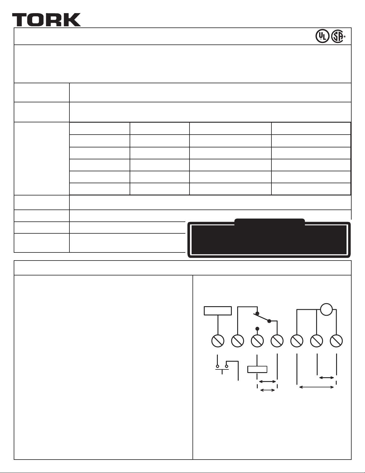
Note: Wiring connections are made to a six-position: terminal block.
All terminals accept AWG #18 to AWG #12 wire.
1. Turn off all power to the timer circuit at the distribution panel before
beginning the installation.
2. The E501T box contains knockouts on two sides. Determine the most
convenient way to mount the box to the conduit and remove the
appropriate knockout. To secure the box to a fixed location, use at
least two of the four box mounting knockouts located on the back of
the box.
3. Wire timer for either 120 VAC or 240 VAC as shown by the wiring
diagram. Wire the load to the timer as shown in the wiring diagram,
noting the contact load type and ratings shown.
4. Connect optional trigger contacts to the timer as shown in the wiring
diagram.
5. Securely attach the timer to Tork’s NEMA 4X (for indoor use only)
non-metallic enclosure with the included screws.
TRIGGER
START NC NO COM 240V/L1 120V NEUT/L2
EXTERNAL
TRIGGER
(CONTACTS)
FOR 120V
(L)
FOR 240V
(L1)
LOAD
FOR 240V
SPDT
120V
LN
L1L2
L1
APPLY ONLY ONE VOLTAGE
FOR 240V
T
120V
LN
L2
Page 4

ON/OFF TIME SETTING INSTRUCTIONS
FOR LOADS USING NORMALLY OPEN (NO) RELAY CONTACTS
To set the INTERVAL ON time:
1. Set dial to the desired length of time that the load (fan, light, etc.) is to be turned on. The dial can be set to various positions within
three different time ranges: 10-45 seconds, 1-45 minutes, and 1-12 hours. The dial can also be set to continuous ON and continuous
OFF positions.
2. The timer will begin timing the desired interval after the dial is set and the START/STOP button is pressed or after closing the external
contacts connected to the START terminal.
3. The timing interval can be restarted by either momentarily pressing the START/STOP button or by closing the external contacts connected to the start terminal.
To set for CONTINOUS ON:
Set dial and align the pointer to the ON position (approximately 12:00 o’clock position). The timer ignores any external trigger signals
in this mode. The green ON LED will illuminate steadily when the timer is set for a continuous ON condition.
To set for CONTINOUS OFF:
Set dial to and align the pointer to the OFF position. The timer ignores any external trigger signals in this mode. The red OFF LED will
illuminate steadily when the timer is set for a continuous OFF condition.
FOR LOADS USING NORMALLY CLOSED (NC) RELAY CONTACT:
The normally closed relay contact is provided to enable a secondary load to be switched at opposite time intervals of the main load
(the load controlled by the normally open contact.) When the load that is connected to the normally open relay contact is ON, the load
connected to the normally closed contact is OFF. When the load that is connected to the normally open relay contact is OFF, the load that
is connected to the normally closed contact is ON.
PROGRAMMING & OPERATING THE TIMER
OPERATING PARAMETERS
• The control relay will be energized continuously if the time interval dial is turned to ON and the START/STOP button is pressed or the external contacts connected to the START terminal are closed. The control relay will be de-energized continuously if the time interval dial is turned to OFF.
• The control will repeat cycle within 1% of timing range.
• The control will automatically reset after a 1 second power interruption and remain OFF with the red OFF LED illuminated steadily until the START/STOP but-
ton is pressed or the external contacts connected to the START terminal are closed.
• If the time interval dial is moved from one position to another during the active timing cycle, the timer immediately terminates the timing cycle, and the
output is disabled. The timer must then be restarted by either pressing the START/STOP button or from external trigger contacts. A timing interval may be
terminated by either pressing the START/STOP button or from external trigger contacts.
ONE YEAR LIMITED WARRANTY: If this product fails because of a manufacturing defect within one year after purchase, we will, at our option, either repair or replace it at no charge.
Our warranty does not cover damage caused by accident, abuse or misuse. We assume no further liability with respect to the sale or use of this product. THIS WARRANTY IS IN LIEU
OF ALL OTHER WARRANTIES, EXPRESSED OR IMPLIED, INCLUDING THE WARRANTY OF MERCHANTABILITY. We make no warranty with respect to the fitness of any goods for the
users particular appplication. This warranty gives you specific legal rights, and you also may have other rights which vary from state to state.
MLI-196(A) NSI INDUSTRIES, LLC • 888.500.4598 • www.nsiindutries.com
A DIVISION OF
NSi INDUSTRIES, LLC
Page 5

®
MINUTERIE à RETARdATEUR dE MISE EN MARCHE
MODÈLE : E501T
La minuterie E501T est conçue pour la temporisation d’intervalles pour de nombreuses applications. Elle permet de régler des intervalles dont la durée varie de 10 secondes (minimum) à 12 heures
(maximum). Elle comprend aussi des réglages de fonctionnement et d’arrêt en continu.
Le choix de l’intervalle de temps est effectué à l’aide d’un cadran rotatif comptant 32 positions précises. Le minutage de l’intervalle de temps choisi peut être lancé (ou arrêté) à l’aide du bouton STOP/
START (démarrer/arrêter) situé à l’avant de la minuterie ou à l’aide d’un interrupteur à rappel commandé à distance. Si un interrupteur à contact maintenu est utilisé pour la téléalimentation, le bouton
qui se trouve à l’avant de la minuterie peut être désactivé.
EXIGENCES
D’ALIMENTATION :
ENVIRONNEMENT :
CAPACITÉ DES
CONTACTS :
BOÎTIER :
ASSEMBLAGE :
CADRANS :
ENTRETIEN :
Signaux d’entrée : 120 et 240 V c.a. (+10 % -15 % à 60 Hz). Signaux de sortie : Contacts de relais unipolaires bidirectionnels à 20 A (normalement ouverts) et
10 A (normalement fermés), usage général : 120 et 240 V c.a.; contact normalement ouvert : 1 HP à 120 V c.a., 2 HP à 240 V c.a.
Gamme des températures de fonctionnement : de 0 ºC à 50 ºC (32 ºF à 122 ºF). Gamme des taux d’humidité relative de fonctionnement : jusqu’à 100 %
Résistance à l’eau : La commande peut supporter un faible débit d’eau direct conformément à la norme NEMA 4X.
TENSION TYPE DE CHARGE
CONTACTS NORMALEMENT
OUVERTS
NORMALEMENT FERMÉS
CONTACTS
120-240 V c.a. Résistive 20 A 10 A
120-240 V c.a. Usage général 20 A 10 A
120 V c.a. Moteur 1 HP ¼ HP
208-240 V c.a. Moteur 2 HP ½ HP
120-240 V c.a. Commande pilote 470 VA 275 VA
Boîtier standard (E501T) NEMA 4x (pour usage à l’intérieur seulement). Le couvercle doté d’un joint d’étanchéité est à l’épreuve du feu, stabilisé
aux rayons UV et non métallique.
La commande peut être installée sur le boîtier non métallique
NEMA 4X de Tork - gris
Accès externe impossible
Nettoyage : Nettoyez le boîtier avec un détergent
MISE EN GARDE :
Un seul sectionneur peut ne pas être suffisant pour mettre l’équipement hors tension avant
l’entretien. Coupez le courant à partir du tableau de distribution principal avant d’installer
ou de réparer cet appareil de commande de l’éclairage ou tout équipement y étant branché.
REMETTEZ L’ISOLATEUR EN PLACE UNE FOIS LE CÂBLAGE EFFECTUÉ.
RISQUE DE CHOC ÉLECTRIQUE
doux et de l’eau seulement.
INSTALLATION ET CÂBLAGE
Remarque : Les connexions du câblage sont effectuées à l’aide d’une
borne à six positions. Toutes les bornes sont conçues pour les fils de calibre
AWG 18 à AWG 12.
1. Avant de commencer l’installation, coupez complètement l’alimentation du
circuit de la minuterie à partir du panneau de distribution.
2. Des pastilles défonçables se trouvent des deux côtés du boîtier de la minuterie E501T. Déterminez la manière la plus pratique d’installer le boîtier
sur le conduit, puis retirez la pastille défonçable appropriée. Pour fixer
le boîtier à un emplacement précis, utilisez au moins deux des quatre
pastilles défonçables qui se trouvent à l’arrière.
3. Procédez au câblage de la minuterie (pour 120 ou 240 V c.a.) conformément au schéma de câblage. Câblez le circuit de charge et la minuterie
conformément au schéma de câblage, en tenant compte du type de charge
et des valeurs nominales.
4. Branchez les contacts du déclencheur optionnel sur la minuterie, comme
l’indique le schéma de câblage.
5. Fixez solidement la minuterie sur le boîtier non métallique NEMA 4X de
Tork (pour usage à l’intérieur seulement) à l’aide des vis incluses.
TRIGGER
DÉCLENCHEUR
START NC NO COM 240V/L1 120V NEUT/L2
MISE EN MARCHE
EXTERNAL
DÉCLENCHEUR
TRIGGER
EXTERNE
(CONTACTOS)
(CONTACTS)
NC NO COM 240V/L1 120V NEUTRE/L2
FOR 120V
POUR 120V
(L)
(L)
FOR 240V
POUR 240V
(L1)
(L1)
LOAD
CHARGE
FOR 240V
POUR 240V
SPDT
SPDT
120V
120V
LN
L1L2
L1
APPLY ONLY ONE VOLTAGE
APPLIQUER UNE SEULE TENSION
FOR 240V
POUR 240V
T
120V
120V
LN
L2
Page 6

INSTRUCTIONS POUR LE RÉGLAGE dES
PÉRIOdES dE MISE EN MARCHE ET d’ARRÊT
POUR LES CHARGES UTILISANT DES CONTACTS DE RELAIS NORMALEMENT OUVERTS
Réglage de l’INTERVALLE DE MISE EN MARCHE :
1. Réglez le cadran en fonction de la période de temps pendant laquelle la charge (ventilateur, luminaire, etc.) doit être en marche. Il
peut être réglé à différentes positions à l’intérieur de trois intervalles de temps différents : de 10 à 45 secondes, de 1 à 45 minutes et
de 1 à 12 heures.
2. Le cadran peut aussi être réglé de manière à rester à ON (marche) ou à OFF (arrêt) en continu. La minuterie commencera à calculer
l’intervalle désiré une fois que le cadran sera réglé et que le bouton START/STOP (démarrer/arrêter) aura été enfoncé ou que les
contacts externes raccordés au terminal START (démarrer) seront fermés.
3. Le calcul de l’intervalle de temps peut être relancé soit en appuyant momentanément sur le bouton START/STOP (démarrer/arrêter) ou
en fermant les contacts externes raccordés au terminal START (démarrer).
Réglage du mode de FONCTIONNEMENT EN CONTINU :
Mettez l’aiguille du cadran en position ON (marche), soit environ à l’endroit où se trouve le 12 sur une horloge. La minuterie ignorera
alors tous les signaux du déclencheur externe. Le voyant à DEL vert ON (marche) brille sans interruption lorsque la minuterie est en
mode de fonctionnement en continu.
Réglage du mode d’ARRÊT EN CONTINU :
Mettez l’aiguille du cadran en position OFF (arrêt). La minuterie ignorera alors tous les signaux du déclencheur externe. Le voyant à
DEL rouge OFF (arrêt) brille sans interruption lorsque la minuterie est en mode d’arrêt en continu.
POUR LES CHARGES UTILISANT UN CONTACT DE RELAIS NORMALEMENT FERMÉ :
Le contact de relais normalement fermé sert à mettre en service une charge secondaire qui sera activée à des intervalles de temps opposés
à ceux de la charge principale (celle qui est activée par le contact de relais normalement ouvert). Lorsque la charge raccordée au contact de
relais normalement ouvert est à ON (marche), celle qui est branchée sur le contact de relais normalement fermé est à OFF (arrêt). Lorsque
la charge raccordée au contact de relais normalement ouvert est à OFF (arrêt), celle qui est branchée sur le contact de relais normalement
fermé est à ON (marche).
PROGRAMMATION ET FONCTIONNEMENT dE LA MINUTERIE
PARAMÈTRES OPÉRATIONNELS
• Le relais de commande sera sous tension de manière continue si le cadran de sélection de l’intervalle de temps est à ON (marche) et si le bouton START/
STOP (démarrer/arrêter) a été enfoncé ou que les contacts externes raccordés au terminal START (démarrer) sont fermés. Il sera hors tension de manière
continue si le cadran de sélection de l’intervalle de temps est à OFF (arrêt).
• La commande recommencera le cycle en tolérant un écart de 1 % au plus par rapport à l’intervalle de temps.
• La commande se réinitialisera automatiquement après une coupure de courant de 1 seconde et restera à OFF (arrêt), le témoin à DEL rouge OFF allumé sans
interruption, jusqu’à ce que le bouton START/STOP (démarrer/arrêter) soit enfoncé ou que les contacts externes raccordés au terminal START (démarrer)
soient fermés.
• Le fait de changer la position de l’aiguille du cadran de sélection de l’intervalle de temps pendant le cycle de synchronisation mettra fin à ce cycle et coupera
le signal de sortie. Il faut ensuite réinitialiser la minuterie en appuyant sur le bouton START/STOP (démarrer/arrêter) ou à l’aide des contacts du déclencheur
externe. Il est possible d’annuler un intervalle de temps en appuyant sur le bouton START/STOP (démarrer/arrêter) ou à l’aide des contacts du déclencheur
externe.
GARANTIE LIMITÉE DE UN AN : Si ce produit s’avère défaillant en raison d’un défaut de fabrication dans une période de un an suivant son achat, nous choisirons, à notre discrétion, de le réparer ou de le remplacer sans frais. Notre garantie ne couvre pas les dommages causés par un accident ou un usage abusif ou inapproprié. Nous déclinons toute autre
responsabilité en ce qui a trait à la vente ou à l’utilisation de ce produit. CETTE GARANTIE PRÉVAUT SUR TOUTE AUTRE GARANTIE, EXPRESSE OU IMPLICITE, Y COMPRIS TOUTE
GARANTIE DE QUALITÉ MARCHANDE. Nous n’offrons aucune garantie quant à l’adaptation de tout produit à l’utilisation particulière que peuvent en faire les utilisateurs. Cette garantie vous confère des droits précis. Il est possible que vous disposiez également d’autres droits, qui varient d’un État ou d’une province à l’autre.
MLI-196(A) NSI INDUSTRIES, LLC • 888.500.4598 • www.nsiindutries.com
A DIVISION OF
NSi INDUSTRIES, LLC
Page 7

®
TEMPORIzAdOR dE INTERVALOS
MODELO#: E501T
El E501T está diseñado para establecer intervalos para una amplia variedad de aplicaciones. Este temporizador se puede ajustar según las especificaciones del usuario, con duraciones de intervalos que
van desde los diez (10) segundos como mínimo a 12 horas como máximo. Se incluyen ajustes de encendido (ON) y apagado (OFF) continuos.
Los intervalos se establecen por medio de un selector rotativo que contiene 32 posiciones definidas con precisión. La selección del tiempo puede iniciarse o detenerse con el botón de encendido y apagado
(STOP/START) en la parte frontal del temporizador o con un interruptor momentáneo remoto. Se puede desactivar el botón de la parte frontal si se utiliza un cierre mantenido del interruptor para la
entrada remota.
REQUISITOS DE
ALIMENTACIÓN:
MEDIO
AMBIENTE:
CLASIFICACIONES
DEL CONTACTO:
CAJA DE
PROTECCIÓN:
MONTAJE:
SELECTORES:
MANTENIMIENTO:
Entradas: 120 y 240 VCA (de +10% a 15%, a 60 Hz). Salidas: Relé SPDT con 20 A N.A. y 10 A N.C. de uso general a 120, 240 VCA; N.A. 1 HP a 120 VCA, 2
HP a 240 VCA
Intervalo de temperaturas de funcionamiento: 32 °F a 122 °F (0 °C a 50 °C). Intervalo de humedad de funcionamiento: Humedad relativa hasta un 100%
Resistente al agua: El control puede realizar un lavado directo con agua de baja presión por debajo de acuerdo con las especificaciones de NEMA 4X.
Voltaje Tipo de carga Contactos N.A. Contactos N.C.
120 a 240 VCA Resistiva 20 A 10 A
120 a 240 VCA Para uso general 20 A 10 A
120 VCA Motor 1 HP ¼ HP
208 a 240 VCA Motor 2 HP ½ HP
120 a 240 VCA
Resistente al agua: El control puede realizar un lavado directo con agua de baja presión por debajo de acuerdo con las especificaciones de NEMA 4X.
Caja de protección: Caja de protección estándar (E501T) NEMA tipo 4X (solo para uso en interiores). La cubierta de sellado hermético con empaquetaduras es ignífuga, resistente a los rayos UV y no metálica en gris
El control se puede montar en la caja de
protección no metálica NEMA 4X de Tork.
Selectores de programación: Sellados contra acceso externo.
Limpieza: Use solamente detergente suave y agua
Capacidad determinada
experimentalmente
470 VA 275 VA
PRECAUCIÓN:
Es posible que se necesite más de un interruptor de desconexión para desenergizar el equipo
antes de realizar de mantenimiento. Desconecte la alimentación en el panel principal antes
de instalar o realizarle mantenimiento a este control de iluminación o al equipo conectado a éste.
VUELVA A COLOCAR EL AISLAMIENTO DESPUÉS DE REALIZAR EL CABLEADO.
RIESGO DE DESCARGA ELÉCTRICA
para limpiar la caja de protección.
INSTALACIÓN Y CABLEAdO
Nota: El cableado se puede conectar a un bloque de terminales de seis
posiciones. Todos los terminales admiten cables de AWG #18 hasta AWG #12.
1. Desconecte por completo la alimentación al circuito del temporizador en el
panel de distribución antes de comenzar con la instalación.
2. La caja del E501T contiene orificios en ambos lados. Determine la forma
más conveniente para montar la caja al conducto y retire el orificio apropiado. Para asegurar la caja a una ubicación fija, utilice al menos dos de
los orificios de montaje ubicados en la parte posterior de la caja.
3. Conecte el temporizador para 120 VCA o 240 VCA como se muestra en el
diagrama de cableado. Conecte la carga al temporizador como se muestra
en el diagrama de cableado, considerando el tipo y los valores nominales
de cargas de contacto que se muestran.
4. Conecte los contactos del disparador opcional al temporizador como se
muestra en el diagrama de cableado.
5. Fije firmemente el temporizador al compartimiento no metálico NEMA 4x
de Tork (solo para uso en interiores) con los tornillos incluidos.
TRIGGER
GATILLO
START NC NO COM 240V/L1 120V NEUT/L2
INICIO
EXTERNAL
GATILLO EXTERNO
TRIGGER
(CONTACTOS)
(CONTACTS)
NC NO COM 240V/L1 120V NEUT/L2
FOR 120V
PARA 120V
(L)
(L)
FOR 240V
PARA 240V
(L1)
(L1)
LOAD
CARGA
FOR 240V
PARA 240V
SPDT
SPDT
120V
120V
LN
L1L2
PARA 240V
APLIQUE SÓLO UN VOLTAJE
T
120V
120V
LN
L2L1
Page 8

INSTRUCCIONES PARA CONFIGURAR LA HORA
dE ENCENdIdO Y APAGAdO
PARA LAS CARGAS QUE UTILIZAN CONTACTOS DE RELÉ NORMALMENTE ABIERTOS (N.A.)
Para congurar el tiempo de intervalo encendido (INTERVAL ON):
Establezca el selector en la duración de tiempo en que la carga (ventilador, luz, etc.) va a estar activa. El selector puede colocarse en
varias posiciones dentro de los tres intervalos de tiempo diferentes: de 10 a 45 segundos, de 1 a 45 minutos y de 1 a 12 horas. El selector
también puede colocarse en posiciones de encendido y apagado continuos. El temporizador comienza a temporizar el intervalo establecido
una vez que se ajusta el selector y luego de presionar el botón de encendido y apagado, o luego de cerrar los contactos externos conectados
al terminal de inicio.
Se puede restablecer el tiempo de intervalo al presionar momentáneamente el botón de encendido y apagado, o al cerrar los contactos
externos conectados al terminal de inicio.
Conguración del encendido continuo (CONTINOUS ON):
Mueva el selector y alinee el puntero en la posición de encendido (aproximadamente en la posición de las 12 en punto). En este modo,
el temporizador omite las señales del disparador externo. El LED verde de encendido permanece iluminado cuando el temporizador
está configurado para mantenerse encendido continuamente.
Conguración del apagado continuo (CONTINOUS OFF):
Mueva el selector y alinee el puntero en la posición de encendido (ON). En este modo, el temporizador omite las señales del disparador
externo. El LED rojo de apagado permanece iluminado cuando el temporizador está configurado para mantenerse apagado continuamente.
PARA LAS CARGAS QUE UTILIZAN CONTACTOS DE RELÉ NORMALMENTE CERRADOS (N.C.):
El contacto del relé normalmente cerrado se proporciona para permitir que se active una carga secundaria en intervalos de tiempo opuestos
de la carga principal (la carga controlada por el contacto normalmente abierto). Cuando se activa la carga conectada al contacto del relé
normalmente abierto, se desactiva la carga conectada al contacto normalmente cerrado. Cuando se desactiva la carga conectada al contacto
del relé normalmente abierto, se activa la carga conectada al contacto normalmente cerrado.
PROGRAMACIÓN Y FUNCIONAMIENTO dEL TEMPORIzAdOR
PARÁMETROS DE FUNCIONAMIENTO
• El relé de control recibe alimentación continuamente si el selector de intervalo de tiempo está en la posición de encendido y si se presiona el botón de encendido y apagado, o si se cierran los contactos externos conectados al terminal de inicio. De lo contrario, el relé de control deja de recibir alimentación de forma
continua si el selector de intervalo de tiempo está en la posición de apagado.
• El control repite el ciclo dentro del 1% del intervalo de tiempo.
• El control se reinicia automáticamente un segundo después de haberse interrumpido la alimentación y permanece apagado con el LED rojo de apagado
iluminado de forma constante hasta que se presione el botón de encendido y apagado, o hasta que se cierren los contactos externos conectados al terminal
de inicio.
• Si se mueve el selector de intervalo de tiempo de una posición a otra durante el ciclo de tiempo activo, el temporizador termina inmediatamente el ciclo de
tiempo y se desactiva la salida. Luego, se debe reiniciar el temporizador al presionar momentáneamente el botón de encendido y apagado, o desde los contactos del disparador externo. Se puede terminar un intervalo de tiempo al presionar el botón de encendido y apagado, o desde los contactos del disparador
externo.
GARANTÍA LIMITADA DE UN AÑO: Si en el lapso de un año a partir de la fecha de compra este artículo falla debido a un defecto en el material, lo reemplazaremos o repararemos
a nuestra discreción sin cargos. Nuestra garantía no cubre daños causados por accidentes, maltrato o uso inadecuado. NO asumimos ninguna otra responsabilidad con respecto a la
venta o uso de este producto. Esta garantía reemplaza todas las DEMÁS garantías, EXPRESAS O IMPLÍCITAS, incluida la garantía DE COMERCIABILIDAD. No garantizamos la idoneidad de ninguna mercancía para un uso en particular. Esta garantía le otorga derechos legales específicos, pero podría tener también otros derechos que varían según el estado.
MLI-196(A) NSI INDUSTRIES, LLC • 888.500.4598 • www.nsiindutries.com
A DIVISION OF
NSi INDUSTRIES, LLC
 Loading...