

Page 1
INSTRUCTION MANUAL
LISTED
DIGITAL TIME SWITCH
24 HOUR
DG180A
DG280A
DG280A-24
FOR TECHNICAL SUPPORT:
888.500.4598
A DIVISION OF NSi INDUSTRIES, LLC
USA • 800.321.5847 • www.nsiindustries.com
MLI-199(A)
Page 2

TABLE OF CONTENTS
Section Page
Installation Instructions and
Capabilities ...........................1
1.0 Clock Format . . . . . . . . . . . . . . . . . . . . . . . . . . 2
2.0 Clock Set Mode . . . . . . . . . . . . . . . . . . . . . . . . 2
3.0 Date Set Mode .........................2
4.0 Daylight Saving Time.....................3
4.1 To Modify Daylight Savings Dates ............3
5.0 Duty Cycle and Signal ....................4
5.1 To set Duty Cycle and Signal ...............5
6.0 Schedule Set Mode ......................6
6.1 Setting Hours and Minutes .................6
7.0 Skip Day Mode . . . . . . . . . . . . . . . . . . . . . . . . 7
7.1 To set Skip Day Mode . . . . . . . . . . . . . . . . . . . . 8
8.0 Review, Modify, and Delete . . . . . . . . . . . . . . . 10
Override Mode........................10
Wiring Diagram .......................13
Schedule Sheets . . . . . . . . . . . . . . . . . . . . 14 -16
Page 3

TORK MODEL
DG180A/DG280A/DG280A-24
7 DAY DIGITAL TIME SWITCH
READ INSTRUCTIONS CAREFULLY BEFORE
ATTEMPTING TO INSTALL TIME SWITCH. SEE
WARNING ON FRONT PANEL – Failure to comply with
instructions could result in personal injury and/or property
damage.
INSTALLATION:
UNIT IS TO BE INSTALLED BY A LICENSED ELECTRICIAN
1. Remove unit from enclosure by pushing the inside
tab (located near the outside hasp) to the right.
Swing unit to left and remove.
2. Mount the enclosure at eye level using screws
or other suitable fastening device. Bring supply
and load wires in through or side knockouts.
DO NOT USE TOP.
3. Reinstall unit by reversing step #1 above and
connecting wires to units as per suggested
wiring diagrams at back of manual.
4. Unit should be programmed with AC power. Do
not program under super cap back up power.
AT POWER UP;
Connect unit to main power source prior to entering the
settings. When powering up the unit for the first time,
allow 1-2 minutes for super cap to charge and the
display will show 12 HOUR. Press reset button after 2
minutes if screen is blank.
CAPABILITIES
- 24 hour scheduling
- 56 set points
- 2 Duty cycle or signal durations (maximum 24 hours)
- Unique “Skip Day” cycle pattern (repeats for up to 31
day cycles)
1
Page 4
FEATURES
Daylight saving - Automatic (user selectable)
Leap year - Automatic compensation
Power outage - Permanent schedule retention. Super
capacitor provides 7 days of real time back up.
Manual override - Until the next scheduled event
AM/PM or 24 hour format - user selectable
Multi-Voltage Input: 120 – 277VAC
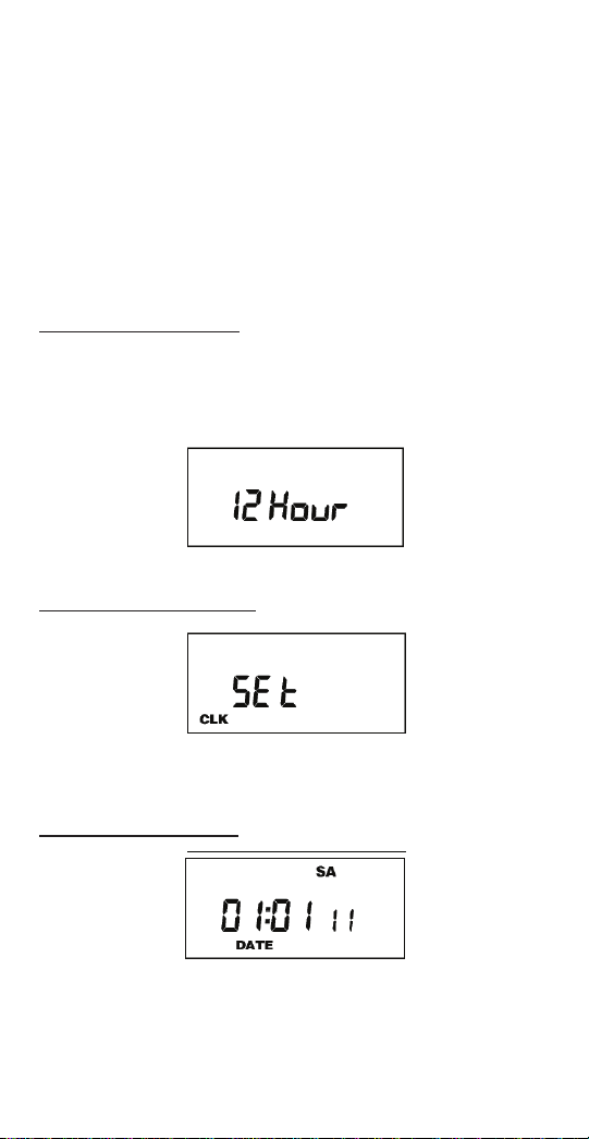
1.0 CLOCK FORMAT
The first time unit is powered up, it will display a
flashing 12 Hour. Use HOUR key to set clock format to
either 12 Hour (AM/PM) or 24 Hour. Press the ENTER
key.
2.0 CLOCK SET MODE
Press HOUR and MIN to advance to the present hour
and minutes. Check AM/PM, and press ENTER.
3.0 DATE SET MODE
2
Page 5
Press MONTH, DATE, and YEAR key to advance to
the desired month, date and year, then press ENTER.
NOTE: The day of the week will automatically set
once the date is entered.
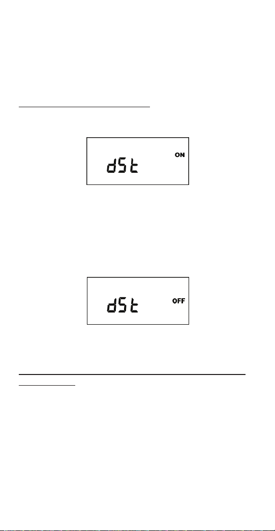
4.0 DAYLIGHT SAVING TIME
After setting or modifying the date, display will show:
a. For standard USA daylight savings (DSt), press
MODE and go to step 5.0.
b. For dates other than standard USA dates, press
MONTH and go to step 4.1.
c. If daylight saving time (DSt) is NOT required, press
DEL display will show:
Press ENTER then go to step 5.0.
4.1 TO MODIFY STANDARD USA DAYLIGHT SAVINGS DATES
NOTE: The first two digits represent the month and
the second set of digits represent the week in the
month. Choices for week are 01 (1st), 02 (2nd), 03
(3rd) or L (Last) week of the month. The default day
3
Page 6
is Sunday (SU.) Once modified date set, the unit will
automatically calculate the correct start dates in the
future.
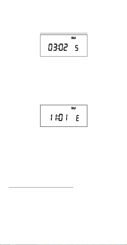
Now press MONTH and DATE buttons to modify the
starting DST settings. Pressing D AY changes default
day. EXAMPLE: A screen showing “04:01 SU S” repre
sents April (04), the first week (01), Sunday (SU), and
the Start (S) of daylight savings time.
Press ENTER to save and the display will show:
Now press MONTH and DATE buttons to modify the
ending DST settings. Pressing DAY changes default
day. EXAMPLE: A screen showing “10: L SU E”
represents October (10), the Last week (L), Sunday
(SU), and the End (E) of daylight savings time.
Press ENTER to save and the display will show the
modified DSt starting date.
Press MODE twice to go to step 5.0.
5.0 DUTY CYCLE AND SIGNAL
The Duty Cycle programming mode begins with a
display that shows the ON duration first for Duty Cycle
1 and the OFF duration second. Programming both
ON and OFF will enable the load to repeatedly turn
ON then OFF.
4
Page 7

The Signal Timer operation can be used by setting only
the ON duration of each duty cycle. Skip the OFF
duration entry. The load will turn ON for the duration of
the ON period, and it will not be repeated.
Once you’ve selected a cycle time, you need to
program the schedule in Section 6.0. Schedule the
events whenever you need to start and end the duty
cycle or to execute a signal, such as school bells.
If not needed, press the MODE key
5.1 TO SET DUTY CYCLE AND SIGNAL
Press either HOUR, MIN, or SEC keys to set the
desired ON duration for the cycle (ON C1).
Press the ENTER key.
a) For signal timer application, press the ENTER key.
b) For a cycle program, press the HOUR, MIN, or SEC
keys to set the time to the desired OFF duration for
the cycle (OFF C1). Press the ENTER key.
5
Page 8

Follow the same procedures above to set the second
signal or duty cycle entries.
Press MODE key to advance to next screen.
6.0 SCHEDULE SET MODE
Press MODE key until display shows:
6.1 SETTING HOURS AND MINUTES
Note: A schedule is needed for each event. If a typical
ON/OFF pair is required, use SCH 01 for the ON
event and SCH 02 for the OFF event.
Press the HOUR, and MIN keys to set the desired time.
Press EVENT to set desired event
(ON or OFF, C1, or C2)
Note: C1 or C2 will not be displayed if the duty cycle
durations are not set in Step 5.
Press CH SELECT key to select channel on
DG280A.
6
Page 9

Press ENTER to save.
Follow the same procedures above to set more
schedule entries.
Press MODE when schedules are complete.
7.0 SKIP DAY MODE
The Skip Day programming allows events to be
repeated for a certain number of days, and then
skipped for a number of days. Both active and skip
periods are set by the user from 1 to 31 days. The
timer will follow the programmed 24 hour schedule
during each day of the active period.
Example: A generator may have an active schedule
for 1 day and then skip 29 days to allow operation
once a month for testing purposes. On the one active
day, a 10 minute schedule may be programmed to start
at 4:00am.
The two channels of the DG280A add additional
programming capabilities in the Skip Day mode.
Alternating days of operation may be set for each
channel. This lets one load be active while the second
load is skipped.
Example: Two pumps are used to operate at alternate
times to extend the life of each pump. An active
schedule may be set so Pump A operates 5 days and
skip 2 days. Pump B can be set to be active on
2 days and skip the other 5. Care must be taken in
programming if the two pumps must not operate at the
same time.
If not needed, press the MODE key
7
Page 10

7.1 SETTING SKIP DAY MODE
Review the Skip Day carefully before
using this feature.
Call the Tork Tech Support line if you have
any question on set-up 888-500-4598.
Press MODE until display shows:
Press D/ON button to set the number of days load will
be active. The first number pair will change.
Press D/OFF button to set the number of days load will
skip. The second number pair will change.
Press DAY button to set today’s position within the
D/ON and D/OFF pattern. The third number pair will
change.
8
Page 11

Example 1: The screen below shows a pattern with 3
active days and 2 skip days with today set as the first
day of skip (01 OFF).
Example 2: For the DG280A with opposite
operations, screen below shows channel 2 set for a
cycle with 2 active days and 3 skip days with today
set as the first active day (01 ON) to be opposite the
first example.
Press MODE when Skip Days are complete.
Unit is in the AUTO (automatic) mode.
The word FLASH may appear to indicate a new
program has been written to memory.
Press the EVENT key once (or twice for two circuit
units) to activate current schedule then EVENT key
again to return to AUTO mode.
9
Page 12

8.0 REVIEW, MODIFY AND DELETE
Press MODE to advance to any of the following
MODES:
1. AUTO MODE: In this automatic mode, the unit will
execute the scheduled programs. Time, day, seconds
and load status are displayed. C1or C2 is displayed
when Duty Cycle is programmed and operating.
OVERRIDE IN AUTO MODE: The load status of the
channel can be manually changed by pressing the
OVRD key (or OVR1 and OVR2 key for DG280A).
The unit will stay in this position until the next scheduled
event. A flashing LCD load indication (ON, OFF) shows
the status was changed by the override not a scheduled
event.
Press the OVRD (or OVR1 and OVR2 key for
DG280A) key until ON or OFF stops flashing to return
to programmed setting.
OVERRIDE IN MAN MODE: The load status of the
channel can be manually changed by pressing the
OVRD key (or OVR1 and OVR2 key for DG280A).
The unit will stay in this position until OVRD is pressed
again. A flashing LCD load indication (ON, OFF)
shows the status was changed by the override not a
scheduled event.
3. CLK MODE: To change the current time press
HOUR and MIN to modify existing settings. Press
ENTER to save changes.
4. DATE MODE: Press MONTH, DATE and YEAR to
modify existing settings. Press ENTER to save
changes. DAY is automatically adjusted.
5. DSt MODE: Factory default is set at US standard
daylight savings dates noted by ON. To remove
daylight savings time setting from, press DEL to change
10
Page 13

screen to show OFF. DST may be activated again by
pressing DEL. Press ENTER to save changes. To change
the from the standard DST month/week/day setting
press HOUR and refer to step 4.1.
6. CYCLE MODE: To change duty cycle timing, press
either the HOUR, MIN, or SEC keys. Press ENTER to
save changes.
7. SCH MODE: To change schedule, press ENTER to
advance to desired event. Press HOUR, MIN, EVENT
to modify time settings. Press DEL to delete. Press
ENTER after each modification to save changes.
8. SKIP MODE: Press D/ON, D/OFF and DAY to
modify existing settings. Press ENTER to save
changes.
NOTES:
1. Unit has a look back feature. Press the EVENT key
once (or twice for two circuit units) to activate current
schedule then EVENT key again to return to the
time (run) screen. Unit will automatically pick up the last
schedule.
2. To clear date and time only and provide unit with
a soft reboot, press and release the reset button that is
recessed under the small hole to right side of LCD
screen.
3. To clear all memory, while in the RUN mode, press
ENTER, display will show:
Use the EVENT key to display:
11
Page 14

Now press ENTER briefly and everything in the timer
memory is wiped off including real time, date and
12HOUR will flash.
4. A “PF” on the display indicates a Power Failure and
the unit requires AC power to operate. The time and
date are protected for 7 days by the super cap. The
program is retained in permanent memory.
5. A “Lo” on the display indicates that the super cap
has run low and the unit needs to be powered with AC.
A minimum of 8 hours is required to fully charge the
super cap.
6. All programs and cycles will end at 1200 a.m. on
the start of a skip day.
7. The CH1 symbol (or CH2 symbol on a two channel)
will flash when in skip day/s. No operations will occur
on channel with flashing symbol.
12
Page 15

120/277VAC
120/277VAC
120/277VAC
DG180A
120/277VAC
DG280A
DG280A-24
13
Page 16

141516
Page 17

Page 18

Page 19

Page 20

A DIVISION OF NSi INDUSTRIES, LLC
USA • 800.321.5847 • www.nsiindustries.com
 Loading...