

Page 1
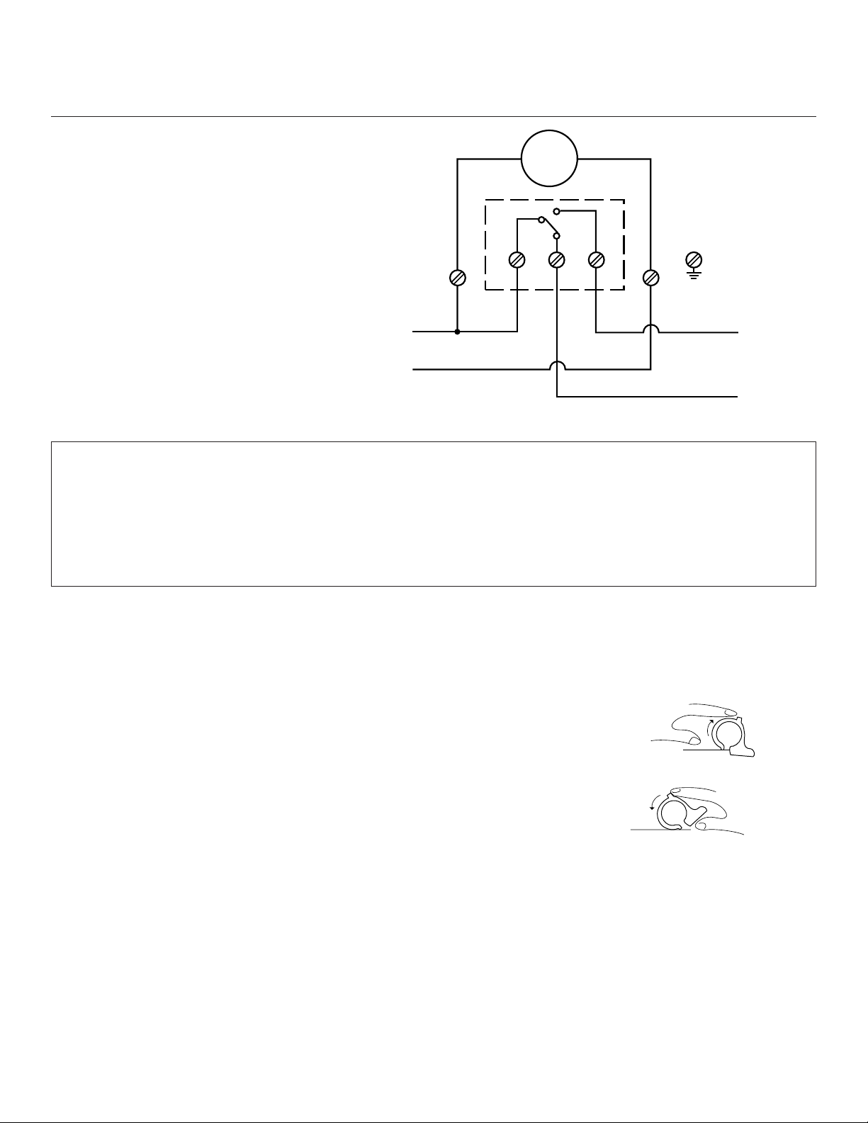
TORK MODEL 8001
DUTY CYCLE TIMER
SWITCH: SPDT
CONTACT RATINGS:
20 AMP 120/240VAC
3/4HP 120VAC;
1-1/2HP 240VAC
TIMING MOTOR:
120VAC 60Hz
POWER CONSUMPTION:
3 WATTS MAX.
INSTALLATION AND OPERATING INSTRUCTIONS
TO SET OPERATING TIMES: Each dial tab represents approximately 15 min-
utes. These tabs can be tilted in and out with the fingers.
FOR OFF OPERATION: Tilt tabs outward as illustrated in
figure 1. Tilt out one tab for each fifteen minute period.
This closes load 2 and opens load 1.
Disconnect power at main panel prior to installing or servicing this
time switch or the equipment connected to it.
Connect in accordance with national and local electrical codes.
Supply Connections: Use gauge specified (AWG # 8-14) suitable for
75 degrees C (167 degrees F)
FOR ON OPERATION: Tilt tabs inward toward center of
dial, as illustrated in figure 2. This closes load 1 and
opens load 2.
TO SET DIAL TO TIME: Turn dial counter-clockwise until correct time is indicated by arrow on nameplate. Be sure to check whether time set is A.M. or P.M.
TO REMOVE MECHANISM FROM CASE: Press lever near case latch to
release mainplate and swing the movement out. To replace, insert mainplate projections in slots opposite latch and swing movement in until it latches.
TORK
®
1 GROVE STREET, MT. VERNON, NY 10550 TEL: 914-664-3542
FAX: 914-664-5052
LI-568(A)
H
120VAC
N
C
L2
NONC
LOAD 2
MOTOR
LOAD 1
CLOSED WITH
TAB INWARD
CLOSED WITH
TAB OUTWARD
Fig. 1
Fig. 2
Page 2
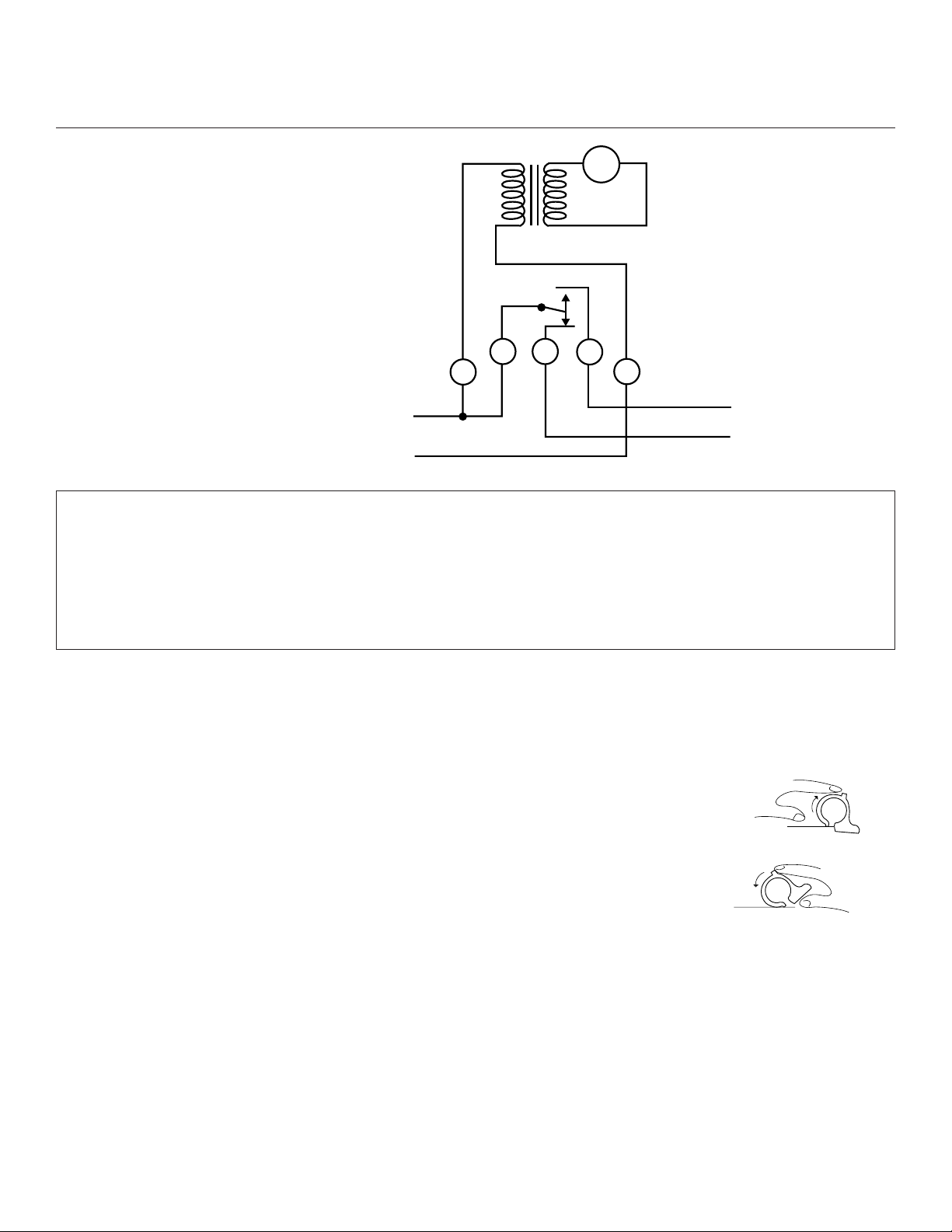
TORK MODEL 8001U
DUTY CYCLE TIMER
SWITCH: SPDT
CONTACT RATINGS:
5 AMP 480VAC
TIMING MOTOR:
120VAC 60Hz
TRANSFORMER:
480VAC/120VAC
POWER CONSUMPTION:
3 WATTS MAX.
INSTALLATION AND OPERATING INSTRUCTIONS
TO SET OPERATING TIMES: Each dial tab represents approximately 15 min-
utes. These tabs can be tilted in and out with the fingers.
FOR OFF OPERATION: Tilt tabs outward as illustrated in figure
1. Tilt out one tab for each fifteen minute period. This closes load
2 and opens load 1.
FOR ON OPERATION: Tilt tabs inward toward center of dial, as
illustrated in figure 2. This closes load 1 and opens load 2.
TO SET DIAL TO TIME: Turn dial counter-clockwise until correct time is indicated by arrow on nameplate. Be sure to check whether time set is A.M. or P.M.
TO REMOVE MECHANISM FROM CASE: Press lever near case latch to
release mainplate and swing the movement out. To replace, insert mainplate projections in slots opposite latch and swing movement in until it latches.
Disconnect power at main panel prior to installing or servicing this
time switch or the equipment connected to it.
Connect in accordance with national and local electrical codes.
Supply Connections: Use gauge specified (AWG # 8-14) suitable for
75 degrees C (167 degrees F)
TORK
®
1 GROVE STREET, MT. VERNON, NY 10550 TEL: 914-664-3542
FAX: 914-664-5052
LI-580(A)
MOTOR
CNC
480V LINE
NO
CLOSED WITH
2L
TAB OUTWARD
CLOSED WITH
TAB INWARD
LOAD 2
LOAD 1
Fig. 1
Fig. 2
Page 3
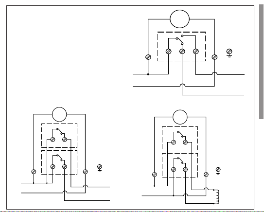
H
N
125VAC
CNC
CNC
MOTOR
LOAD 1
LOAD 2
®
LISTED
U
L
®
ALL SPDT
MODELS
Model
8002N
DPST
MOTOR
C
MOTOR
NONC
Model
L2
H
120VAC
N
8042N
CNC
DPST
LOAD 2
CLOSED WITH
TAB OUTWARD
LOAD 1
CLOSED WITH
TAB INWARD
H
208-250VAC
H
CNC
LOAD
STARTER
COIL
OR MOTOR
Page 4

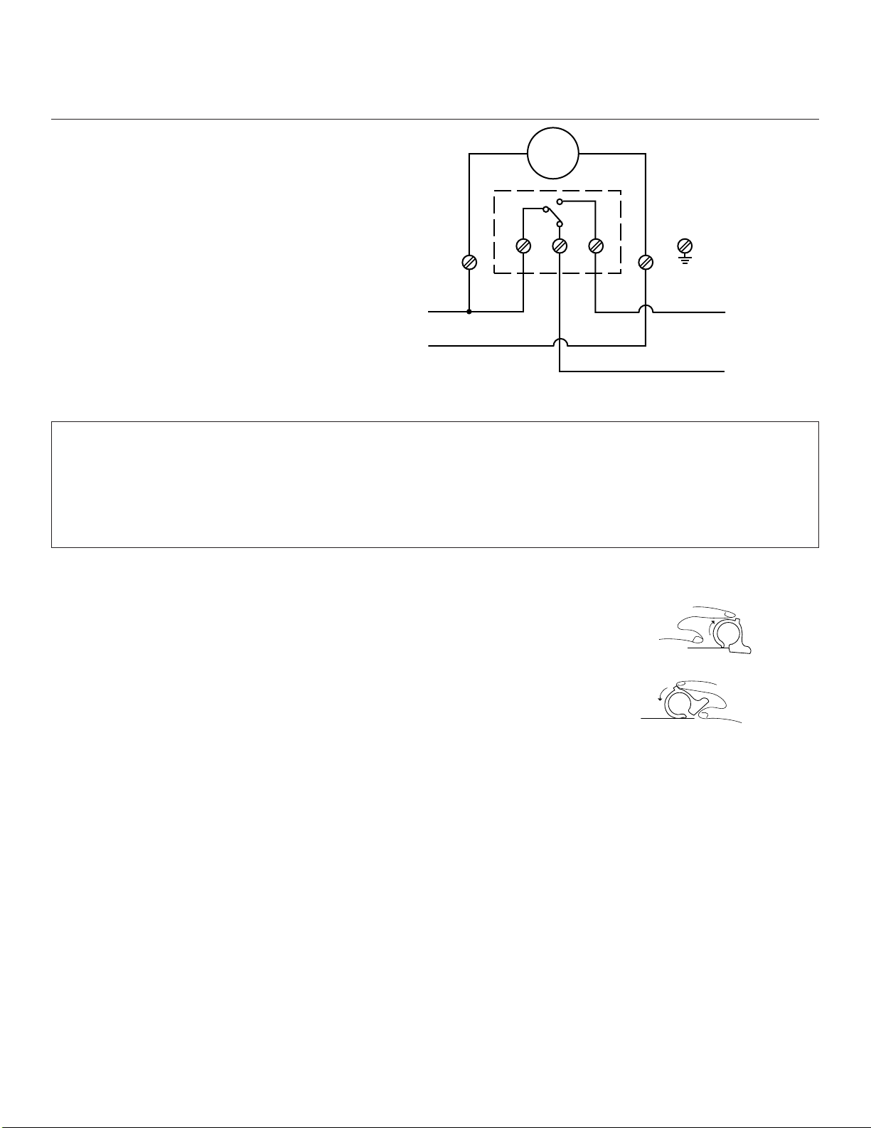
TORK MODEL 8004
DUTY CYCLE TIMER
SWITCH: SPDT
CONTACT RATINGS:
20 AMP 120/240VAC
3/4HP 120VAC;
1-1/2HP 240VAC
TIMING MOTOR:
208-277VAC 60Hz
POWER CONSUMPTION:
3 WATTS MAX.
INSTALLATION AND OPERATING INSTRUCTIONS
TO SET OPERATING TIMES: Each dial tab represents approximately 15 min-
utes. These tabs can be tilted in and out with the fingers.
FOR OFF OPERATION: Tilt tabs outward as illustrated in
figure 1. Tilt out one tab for each fifteen minute period. This
closes load 2 and opens load 1.
FOR ON OPERATION: Tilt tabs inward toward center of dial,
as illustrated in figure 2. This closes load 1 and opens load 2.
TO SET DIAL TO TIME: Turn dial counter-clockwise until correct time is indicated by arrow on nameplate. Be sure to check whether time set is A.M. or P.M.
TO REMOVE MECHANISM FROM CASE: Press lever near case latch to
release mainplate and swing the movement out. To replace, insert mainplate projections in slots opposite latch and swing movement in until it latches.
Disconnect power at main panel prior to installing or servicing this
time switch or the equipment connected to it.
Connect in accordance with national and local electrical codes.
Supply Connections: Use gauge specified (AWG # 8-14) suitable for
75 degrees C (167 degrees F)
TORK
®
1 GROVE STREET, MT. VERNON, NY 10550 TEL: 914-664-3542
FAX: 914-664-5052
LI-574(A)
H
120VAC
N
C
L2
NONC
LOAD 2
MOTOR
LOAD 1
CLOSED WITH
TAB INWARD
CLOSED WITH
TAB OUTWARD
208-277VAC
Fig. 1
Fig. 2
Page 5
TORK MODEL 8007
DUTY CYCLE TIMER WITH OMITTING DEVICE
SWITCH: SPDT
CONTACT RATINGS:
20 AMP 120/240VAC
3/4HP 120VAC;
1-1/2HP 240VAC
TIMING MOTOR:
120VAC 60Hz
POWER CONSUMPTION:
3 WATTS MAX.
INSTALLATION AND OPERATING INSTRUCTIONS
TO SET OPERATING TIMES: Each dial tab represents approximately 15
minutes. These tabs can be tilted in and out with the fingers.
FOR OFF OPERATION: Tilt tabs outward as illustrated in figure 1. Tilt
out one tab for each fifteen minute period. This closes load 2 and opens
load 1.
FOR ON OPERATION: Tilt tabs inward toward center of dial, as illustrated
in figure 2. This closes load 1 and opens load 2.
TO SET DIAL TO TIME: Tur n dial counter-clockwise until correct time is indicated by arrow on nameplate. Be sure to check whether time set is A.M. or P.M.
TO OMIT OPERATIONS: 7 spoke wheel at lower right of 24 hour dial moves ahead once each day at
about 2:00 A.M. Insert brass knurled screw in appropriate spokes on days when load 1 should
remain open (load 2 remains closed). CAUTION: Do not attempt to insert screw in spoke while it is
pointing to the copper colored arrow. If necessary, turn seven spoke wheel, then insert screw.
TO SET OMITTING WHEEL TO CORRECT DAY: If setting is being made later than 2:00 A.M. turn
omitting wheel CLOCKWISE until present day of week is indicated by copper arrow. (Between midnight and 2:00 A.M., setting must be made to day just ended at midnight.)
TO REMOVE MECHANISM FROM CASE: Press lever near case latch to release mainplate and
swing the movement out. To replace, insert mainplate projections in slots opposite latch and swing
movement in until it latches.
Disconnect power at main panel prior to installing or servicing this
time switch or the equipment connected to it.
Connect in accordance with national and local electrical codes.
Supply Connections: Use gauge specified (AWG # 8-14) suitable for
75 degrees C (167 degrees F)
TORK
®
1 GROVE STREET, MT. VERNON, NY 10550 TEL: 914-664-3542
FAX: 914-664-5052
LI-569(A)
H
120VAC
N
C
L2
NONC
LOAD 2
MOTOR
LOAD 1
CLOSED WITH
TAB INWARD
CLOSED WITH
TAB OUTWARD
Fig. 1
Fig. 2
Page 6

TORK MODEL 8007V
DUTY CYCLE TIMER
SWITCH: SPDT
CONTACT RATINGS:
20 AMP 120/240VAC
3/4HP 120VAC;
1-1/2HP 240VAC
TIMING MOTOR:
120VAC 60Hz
POWER CONSUMPTION:
3 WATTS MAX.
TO ALTERNATE CIRCUITS ONCE EACH WEEK, leave all dial tabs in ON
position and turn 7 consecutive omitting screws down and leave the other 7
turned out.
TO SET OPERATING TIMES: Each dial tab represents approximately 15 minutes. These tabs can be tilted in and out with the fingers.
FOR OFF OPERATION: Tilt tabs out-ward as illustrated in figure 1. Tilt out one
tab for each fifteen minute period. This closes load 2 and opens load 1.
FOR ON OPERATION: Tilt tabs inward toward center of dial, as illustrated in figure 2. This closes
load 1 and opens load 2.
TO SET TO TIME OF DAY: Turn dial counter-clockwise until the correct time of day is indicated by
the arrow in center of 24 hour dial. Be sure to check whether time set is A.M. or P.M.
TO SELECT DAY OR DAYS OF THE WEEK FOR OPERATION: 14 spoke calendar wheel at lower
right of dial rotates one revolution per 2 weeks. For day no ON operation is to occur (Load #2 remains
energized), simply turn down the brass knurled screws of the appropriate spokes. CAUTION: Do not
attempt to turn down screw in spoke while it is pointing to the black arrow. If necessary, tur n 14 spoke
wheel, then turn down screw.
TO SET 14 SPOKE WHEEL TO CORRECT DAY:
1.Turn dial counter-clockwise until special tab at 12:00 P.M. advances 14 spoke wheel.
2.Turn 14 spoke wheel by hand until spoke, indicating present day of week is pointing to black arrow
(in operation, present day is always in this position).
3.Reset dial to correct time of day.
Disconnect power at main panel prior to installing or servicing this
time switch or the equipment connected to it.
Connect in accordance with national and local electrical codes.
Supply Connections: Use gauge specified (AWG # 8-14) suitable for
75 degrees C (167 degrees F)
TORK
®
1 GROVE STREET, MT. VERNON, NY 10550 TEL: 914-664-3542
FAX: 914-664-5052
LI-522(B)
H
120VAC
N
C
L2
NONC
LOAD 2
MOTOR
LOAD 1
CLOSED WITH
TAB INWARD
CLOSED WITH
TAB OUTWARD
Fig. 1
Fig. 2
Page 7

TORK MODEL 8008
DUTY CYCLE TIMER WITH OMITTING DEVICE
SWITCH: SPDT
CONTACT RATINGS:
20 AMP 120/240VAC
3/4HP 120VAC;
1-1/2HP 240VAC
TIMING MOTOR:
208-277VAC 60Hz
POWER CONSUMPTION:
3 WATTS MAX.
INSTALLATION AND OPERATING INSTRUCTIONS
TO SET OPERATING TIMES: Each dial tab represents approximately 15
minutes. These tabs can be tilted in and out with the fingers.
FOR OFF OPERATION: Tilt tabs outward as illustrated in figure 1. Tilt out
one tab for each fifteen minute period. This closes load 2 and opens load 1.
FOR ON OPERATION: Tilt tabs inward toward center of dial, as illustrated
in figure 2. This closes load 1 and opens load 2.
TO SET DIAL TO TIME: Tur n dial counter-clockwise until correct time is indicated by arrow on name-
plate. Be sure to check whether time set is A.M. or P.M.
TO OMIT OPERATIONS: 7 spoke wheel at lower right of 24 hour dial moves ahead once each day at
about 2:00 A.M. Insert brass knurled screw in appropriate spokes on days when load 1 should remain
open (load 2 remains closed). CAUTION: Do not attempt to insert screw in spoke while it is pointing
to the copper colored arrow. If necessary, turn seven spoke wheel, then insert screw.
TO SET OMITTING WHEEL TO CORRECT DAY: If setting is being made later than 2:00 A.M. turn
omitting wheel CLOCKWISE until present day of week is indicated by copper arrow. (Between midnight and 2:00 A.M., setting must be made to day just ended at midnight.)
TO REMOVE MECHANISM FROM CASE: Press lever near case latch to release mainplate and
swing the movement out. To replace, insert mainplate projections in slots opposite latch and swing
movement in until it latches.
Disconnect power at main panel prior to installing or servicing this
time switch or the equipment connected to it.
Connect in accordance with national and local electrical codes.
Supply Connections: Use gauge specified (AWG # 8-14) suitable for
75 degrees C (167 degrees F)
TORK
®
1 GROVE STREET, MT. VERNON, NY 10550 TEL: 914-664-3542
FAX: 914-664-5052
LI-573(A)
208-277VAC
MOTOR
L2
H
120VAC
N
C
NONC
LOAD 2
CLOSED WITH
TAB OUTWARD
LOAD 1
CLOSED WITH
TAB INWARD
Fig. 1
Fig. 2
Page 8

TORK MODEL 8011
1 MINUTE REPEATING TIMER
SWITCH: SPDT
CONTACT RATINGS:
20 AMP 120/240VAC
3/4HP 120VAC;
1-1/2HP 240VAC
TIMING MOTOR:
120VAC 60Hz
POWER CONSUMPTION:
3 WATTS MAX.
INSTALLATION AND OPERATING INSTRUCTIONS
TO SET OPERATING TIMES: Each dial tab represents approximately 1 second.
These tabs can be tilted in and out with the fingers.
FOR OFF OPERATION: Tilt tabs outward as illustrated in figure
1. Tilt out one tab for each 1 second period. This closes load 2
and opens load 1.
FOR ON OPERATION: Tilt tabs inward toward center of dial, as
illustrated in figure 2. This closes load 1 and opens load 2.
TO REMOVE MECHANISM FROM CASE: Press lever near case latch to
release mainplate and swing the movement out. To replace, insert mainplate projections in slots opposite latch and swing movement in until it latches.
Disconnect power at main panel prior to installing or servicing this
time switch or the equipment connected to it.
Connect in accordance with national and local electrical codes.
Supply Connections: Use gauge specified (AWG # 8-14) suitable for
75 degrees C (167 degrees F)
TORK
®
1 GROVE STREET, MT. VERNON, NY 10550 TEL: 914-664-3542
FAX: 914-664-5052
LI-579(A)
H
120VAC
N
C
L2
NONC
LOAD 2
MOTOR
LOAD 1
CLOSED WITH
TAB INWARD
CLOSED WITH
TAB OUTWARD
Fig. 1
Fig. 2
Page 9

®
LISTED
U
L
®
MOTOR
C
L2
H
120VAC
N
NONC
LOAD 2
CLOSED WITH
TAB OUTWARD
LOAD 1
CLOSED WITH
TAB INWARD
Page 10

TORK MODEL 8121
12 MINUTE REPEATING TIMER
SWITCH: SPDT
CONTACT RATINGS:
20 AMP 120/240VAC
3/4HP 120VAC;
1-1/2HP 240VAC
TIMING MOTOR:
120VAC 60Hz
POWER CONSUMPTION:
3 WATTS MAX.
INSTALLATION AND OPERATING INSTRUCTIONS
TO SET OPERATING TIMES: Each dial tab represents approximately 12 sec-
onds. These tabs can be tilted in and out with the fingers.
FOR OFF OPERATION: Tilt tabs outward as illustrated in figure
1. Tilt out one tab for each 12 second period. This closes load 2
and opens load 1.
FOR ON OPERATION: Tilt tabs inward toward center of dial, as
illustrated in figure 2. This closes load 1 and opens load 2.
TO REMOVE MECHANISM FROM CASE: Press lever near case latch to
release mainplate and swing the movement out. To replace, insert mainplate projections in slots opposite latch and swing movement in until it latches.
Disconnect power at main panel prior to installing or servicing this
time switch or the equipment connected to it.
Connect in accordance with national and local electrical codes.
Supply Connections: Use gauge specified (AWG # 8-14) suitable for
75 degrees C (167 degrees F)
TORK
®
1 GROVE STREET, MT. VERNON, NY 10550 TEL: 914-664-3542
FAX: 914-664-5052
LI-577(A)
H
120VAC
N
C
L2
NONC
LOAD 2
MOTOR
LOAD 1
CLOSED WITH
TAB INWARD
CLOSED WITH
TAB OUTWARD
Fig. 1
Fig. 2
Page 11

TORK MODEL 8150
SWITCH: SPST
CONTACT RATINGS:
10 AMP 120/240VAC
3/4HP 120VAC
TIMING MOTOR:
120VAC 60Hz
POWER CONSUMPTION:
3 WATTS MAX.
INSTALLATION AND OPERATING INSTRUCTIONS
TO SET OPERATING TIMES: Each dial tab represents approx-
imately 15 minutes. These tabs can be tilted in and out with the
fingers.
FOR ON OPERATION: Tilt tabs out-ward as illustrated in figure
1. Tilt out one tab for each fifteen minute period.
FOR OFF OPERATION: Tilt tabs inward toward center of dial, as illustrated in
figure 2.
TO SET DIAL TO TIME: Tur n dial counter-clockwise until correct time is indicat-
ed by arrow on nameplate. Be sure to check whether time set is A.M. or P.M.
TO SET DELAY: Delay is manually adjustable from 0-8 minutes. Turn “DELAY
CONTROL” clockwise for longer delay, counter-clockwise for shorter delay.
TO REMOVE MECHANISM FROM CASE: Press lever near case latch to
release mainplate and swing the movement out. To replace, insert mainplate projections in slots opposite latch and swing movement in until it latches.
Disconnect power at main panel prior to installing or servicing this
time switch or the equipment connected to it.
Connect in accordance with national and local electrical codes.
Supply Connections: Use gauge specified (AWG # 8-14) suitable for
75 degrees C (167 degrees F)
TORK
®
1 GROVE STREET, MT. VERNON, NY 10550 TEL: 914-664-3542
FAX: 914-664-5052
LI-562(A)
L 2
H
N
120V, 60 Hz
CNC NO
LOAD
DELAY
SWITCH
SUSTAINED
SWITCH
M
Fig. 1
Fig. 2
Page 12

M
DELAY
SWITCH
L 2
H
N (120V)
H (480V)
SUSTAINED
SWITCH
CNC NO
LOAD
8150 Series
Page 13

TORK MODEL 8150U
SWITCH: SPST
CONTACT RATINGS:
5 AMP 480VAC
3/4HP 120VAC
TRANSFORMER:
480/120VAC
TIMING MOTOR:
120VAC 60Hz
POWER CONSUMPTION:
3 WATTS MAX.
INSTALLATION AND OPERATING INSTRUCTIONS
TO SET OPERATING TIMES: Each dial tab represents approx-
imately 15 minutes. These tabs can be tilted in and out with the
fingers.
FOR ON OPERATION: Tilt tabs out-ward as illustrated in figure
1. Tilt out one tab for each fifteen minute period.
FOR OFF OPERATION: Tilt tabs inward toward center of dial, as illustrated in
figure 2.
TO SET DIAL TO TIME: Tur n dial counter-clockwise until correct time is indicat-
ed by arrow on nameplate. Be sure to check whether time set is A.M. or P.M.
TO SET DELAY: Delay is manually adjustable from 0-8 minutes. Turn “DELAY
CONTROL” clockwise for longer delay, counter-clockwise for shorter delay.
TO REMOVE MECHANISM FROM CASE: Press lever near case latch to
release mainplate and swing the movement out. To replace, insert mainplate projections in slots opposite latch and swing movement in until it latches.
Disconnect power at main panel prior to installing or servicing this
time switch or the equipment connected to it.
Connect in accordance with national and local electrical codes.
Supply Connections: Use gauge specified (AWG # 8-14) suitable for
75 degrees C (167 degrees F)
TORK
®
1 GROVE STREET, MT. VERNON, NY 10550 TEL: 914-664-3542
FAX: 914-664-5052
LI-563(A)
480VAC
DELAY
SWITCH
SUSTAINED
SWITCH
C
H
H
NC NO
LOAD
MOTOR
L2
Fig. 1
Fig. 2
Page 14

TORK MODEL 8301
30 MINUTE REPEATING TIMER
SWITCH: SPDT
CONTACT RATINGS:
20 AMP 120/240VAC
3/4HP 120VAC;
1-1/2HP 240VAC
TIMING MOTOR:
120VAC 60Hz
POWER CONSUMPTION:
3 WATTS MAX.
INSTALLATION AND OPERATING INSTRUCTIONS
TO SET OPERATING TIMES: Each dial tab represents approximately 30 sec-
onds. These tabs can be tilted in and out with the fingers.
FOR OFF OPERATION: Tilt tabs outward as illustrated in figure 1.
Tilt out one tab for each 30 second period. This closes load 2
and opens load 1.
FOR ON OPERATION: Tilt tabs inward toward center of dial, as
illustrated in figure 2. This closes load 1 and opens load 2.
TO REMOVE MECHANISM FROM CASE: Press lever near case latch to
release mainplate and swing the movement out. To replace, insert mainplate projections in slots opposite latch and swing movement in until it latches.
Disconnect power at main panel prior to installing or servicing this
time switch or the equipment connected to it.
Connect in accordance with national and local electrical codes.
Supply Connections: Use gauge specified (AWG # 8-14) suitable for
75 degrees C (167 degrees F)
TORK
®
1 GROVE STREET, MT. VERNON, NY 10550 TEL: 914-664-3542
FAX: 914-664-5052
LI-576(A)
H
120VAC
N
C
L2
NONC
LOAD 2
MOTOR
LOAD 1
CLOSED WITH
TAB INWARD
CLOSED WITH
TAB OUTWARD
Fig. 1
Fig. 2
Page 15

TORK MODEL 8061
6 MINUTE REPEATING TIMER
SWITCH: SPDT
CONTACT RATINGS:
20 AMP 120/240VAC
3/4HP 120VAC;
1-1/2HP 240VAC
TIMING MOTOR:
120VAC 60Hz
POWER CONSUMPTION:
3 WATTS MAX.
INSTALLATION AND OPERATING INSTRUCTIONS
TO SET OPERATING TIMES: Each dial tab represents approximately 6 sec-
onds. These tabs can be tilted in and out with the fingers.
FOR OFF OPERATION: Tilt tabs outward as illustrated in
figure 1. Tilt out one tab for each 6 second period. This
closes load 2 and opens load 1.
FOR ON OPERATION: Tilt tabs inward toward center of
dial, as illustrated in figure 2. This closes load 1 and opens
load 2.
TO REMOVE MECHANISM FROM CASE: Press lever near case latch to
release mainplate and swing the movement out. To replace, insert mainplate projections in slots opposite latch and swing movement in until it latches.
Disconnect power at main panel prior to installing or servicing this
time switch or the equipment connected to it.
Connect in accordance with national and local electrical codes.
Supply Connections: Use gauge specified (AWG # 8-14) suitable for
75 degrees C (167 degrees F)
TORK
®
1 GROVE STREET, MT. VERNON, NY 10550 TEL: 914-664-3542
FAX: 914-664-5052
LI-578(A)
H
120VAC
N
C
L2
NONC
LOAD 2
MOTOR
LOAD 1
CLOSED WITH
TAB INWARD
CLOSED WITH
TAB OUTWARD
Fig. 1
Fig. 2
Page 16

TORK MODEL 8602
60 MINUTE REPEATING TIMER
SWITCH: SPDT
CONTACT RATINGS:
20 AMP 120/240VAC
3/4HP 120VAC;
1-1/2HP 240VAC
TIMING MOTOR:
208-277VAC 60Hz
POWER CONSUMPTION:
3 WATTS MAX.
INSTALLATION AND OPERATING INSTRUCTIONS
60 MINUTE DIAL: 1 to 30 ON-OFF operations per hour. 60 tabs permit 1 minute
switching changes. Cycles adjustable from 2, 3, 4, 5, 6, 10, 12, 15, 20, 30, or 60
minutes, with 1 minute minimum ON and/or OFF settings.
TO SET OPERATING TIMES: Each dial tab represents approximately 1 minute.
These tabs can be tilted in and out with the fingers.
FOR OFF OPERATION: Tilt tabs outward as illustrated in
figure 1. Tilt out one tab for each 1 minute period. This closes
load 2 and opens load 1.
FOR ON OPERATION: Tilt tabs inward toward center of dial,
as illustrated in figure 2. This closes load 1 and opens load 2.
TO REMOVE MECHANISM FROM CASE: Press lever near case latch to
release mainplate and swing the movement out. To replace, insert mainplate projections in slots opposite latch and swing movement in until it latches.
Disconnect power at main panel prior to installing or servicing this
time switch or the equipment connected to it.
Connect in accordance with national and local electrical codes.
Supply Connections: Use gauge specified (AWG # 8-14) suitable for
75 degrees C (167 degrees F)
TORK
®
1 GROVE STREET, MT. VERNON, NY 10550 TEL: 914-664-3542
FAX: 914-664-5052
LI-572(A)
H
120VAC
N
C
L2
NONC
LOAD 2
MOTOR
LOAD 1
CLOSED WITH
TAB INWARD
CLOSED WITH
TAB OUTWARD
208-277VAC
Fig. 1
Fig. 2
 Loading...