

Page 1
ND 4600/ ND 5000
ADDRESSABLE DIMMER PACKS
OPERATION MANUAL
Page 1 of 9
Page 2

Dimmer packs are the heart of any stage lighting system. They translate coded signals
o power levels required to drive high power lamps to desired
The NSI ND 4600 and ND 5000 satellite dimmer packs are both fully user addressable
eight control channels.
hnology, developed by NSI for the stage lighting market, is the electrical
marriage of microprocessor technology with digitally controlled multiplexing. Microplex
technology allows your system to be connected using standard microphone cables or even
snakes. System expansion is further simplified through the ability to daisy chain
additional dimmer packs to an existing system. This application of Microplex technology
been
known to be compatible with other manufacturer's lighting products that use the same
microphone cable interface.
Our philosophy at NSI is to utilize only the highest quality components. Problems that
zing in audio equipment and triac failure are
minimized with toroidal devices. In place of triacs, NSI only uses professional grade dual
SCR's.
You can be confident your NSI dimmer packs feature the best performance and
reliability standards available.
INTRODUCTION
generated by controllers int
intensities.
allowing assignment of four of a possible one hundred twentyMicroplex tec
audio
makes system set up and operation easy and convenient. In addition, NSI products have
often plague dimmers such as flickering lights, buz
Page 2 of 9
Page 3

-
ND 5000
ND 4600
No. of Channels:
(4) chokes
(4) chokes
NSI"Microplex"
NSI"Microplex"
Four
Power Output per Channel:
Total Maximum Power Output:
Filtering:
SPECIFICATIONS
Four
600 Watts 1200 Watts
2400 Watts 2400 Watts
160USEC.
400 USEC.
Serial Control System:
Input Voltage to Output Response Time:
Control Isolation:
+15 V DC Available to Controller:
Dimensions (HxWxD):
Weight:
Mounting Spec. (from hole centers):
50 MSEC.
1200 Volt HV
400 MA
8"x9.5"x3.5"
7.51bs
8.25"
50 MSEC.
1200 Volt HV
400 MA
8" x9.5"x3.5"
10 lbs
8.25"
Page 3 of 9
Page 4

eight
may be assigned in increments of four by addressing
the dimmer packs to receive them. To accomplish this simply position the address select
Note: New Style units have six position dipswitches where as dips
6 are indicated below. Old
style units are functionally the same but offered 4 position dipswitches. Additional dips were internal
jumpers where as J1, J2 are indicated below.
4. Units
ADDRESSING
Each NSI dimmer pack is fully user addressable to receive any of one hundred twentypossible control signals. Control signals
dipswitches as described in the following chart.
witches 1-
Channels 1 2 3 4 5/J2 6/J2
1-4 Off Off Off Off Off N/A
5-8 On Off Off Off Off N/A
9-12 Off On Off Off Off N/A
13-16 On On Off Off Off N/A
17-20 Off Off On Off Off N/A
21-24 On Off On Off Off N/A
25-28 Off On On Off Off N/A
29-32 On On On Off Off N/A
33-36 Off Off Off On Off N/A
37-40 On Off Off On Off N/A
41-44 Off On Off On Off N/A
45-48 On On Off On Off N/A
49-52 Off Off On On Off N/A
53-56 On Off On On Off N/A
57-60 Off On On On Off N/A
61-64 On On On On Off N/A
65-68 Off Off Off Off On N/A
69-72 On Off Off Off On N/A
73-76 Off On Off Off On N/A
77-80 On On Off Off On N/A
81-84 Off Off On Off On N/A
85-88 On Off On Off On N/A
89-92 Off On On Off On N/A
93-96 On On On Off On N/A
97-100 Off Off Off On On N/A
101-104 On Off Off On On N/A
105-108 Off On Off On On N/A
109-112 On On Off On On N/A
113-116 Off Off On On On N/A
117-120 On Off On On On N/A
121-124 Off On On On On N/A
125-128 On On On On On N/A
IMPORTANT: All NSI dimmer packs are shipped from the factory addressed for channels 1 must be readdressed (see chart above) before being capable of receiving any other channels.
Page 4 of 9
Page 5

in test function allows you to connect and test lamps at full intensity without the
need of a controller. When dipswitch #6 is off and your dimmer pack is receiving AC power
a controller is not connected lamps will light to full intensity. Internal jumper J2 is used in
place of dipswitch # 6 on old style units.
Individual yellow LED's (Light Emitting Diodes) for each channel indicate when the dimmer is
shooting tool in identifying
possible problems with signal transmissions or defective lamps and fixtures.
all of the ac power
consumed by lights connected to the dimmer. It must be connected to a power source capable
of supplying the total power drawn by the lights (see specification section of this manual for
details on maximum power capability).
Do not remove grounding prong of AC plug. To do so may cause exposure to
potentially lethal voltage levels and will void the warranty on this product.
dimmer pack is receiving AC
Both the ND 4600 and ND 5000 are equipped with safety circuit interruption devices to protect
the units from becoming overloaded. The ND 4600 utilizes fusing while the ND 5000 features
a resetabl
e external circuit breaker as well as internal fusing.
NSI ND 4600 and ND 5000 dimmer packs are designed to be mounted vertically. Each dimmer
pack is provided with two mounting flanges or ears designed for securing to the center of truss
st truss bars are already properly drilled to accept mounting of dimmers, however in
some cases you may need to drill holes in your truss bar to accommodate your dimmer pack.
AUTO TEST
This built-
and
LEVEL LED's
receiving control signals. This feature is an excellent trouble-
This is the main power cord for your dimmer pack which ultimately carries
AC POWER CABLE
WARNING:
POWER INDICATOR
This green LED (Light Emitting Diode) will light whenever the
power and functioning properly.
CIRCUIT PROTECTION
MOUNTING
bars. Mo
Page 5 of 9
Page 6

or each channel of both the ND 4600 and
ND 5000. These receptacles provide power to the lamps in your lighting system. The amount of
power supplied to these outlets control the intensity of the lights they drive. Multiplexed signals
controller are translated into power levels to achieve the desired light
intensity. Each dual receptacle corresponds to a single channel with the maximum power
capabilities described in the specifications section of this manual. Under no circumstances
ld maximum recommended power capabilities be exceeded. To do so may be hazardous
and will void your warranty. Most incandescent lamps and fixtures may be connected to these
outlets. Do not connect any other electrical appliances or equipment to the dimmer
packs.
Both the male and female Microplex connectors may be used for input signals. Microplex
technology allows your system to be connected using standard microphone cables or even audio
controller or another dimmer pack. The
Microplex system also provides D.C. phantom power to your control unit eliminating the need
eight individual control
ur controller may be transmitted through a single
microphone cable.
The male and female Microplex connectors are wired in parallel allowing either one to be used
Microplex connectors will
provide control signals to another dimmer pack. This is called daisy chaining and makes
expansion of your system easily.
AC OUTPUT RECEPTACLES
Dual standard AC outlet receptacles are provided f
received from your NSI
shou
MICROPLEX INPUTS
snakes. Microplex may be received from your NSI
for AC power cords on any NSI controller. Up to one hundred twentychannels plus phantom power to yo
MICROPLEX EXPANSION
for input or output of control signals. When used as an output, the
Page 6 of 9
Page 7

3) Ensure that the rating of the breaker or fuse for the chosen outlet is adequate. The required
rating (in amps) of the breaker or fuse may be calculated with the following formula:
For example: if you are using six, 300 watt lamps (1800 watts total), you should have at least a
15 amp electrical service.
OPERATIONAL HINTS
1) Always place your dimmer packs as close as possible to the lights they are powering.
This will reduce the number of extension cords required to hook up your system.
2) Use a power outlet located as close as possible to an electrical service panel (fuse box). It is
best if the power outlet is on a separate circuit breaker or fuse from your audio system.
Where I = the current (in amps)
P = the power (in watts)
And E = the voltage (in volts)
I = P/E
4) Always use quality 14 gauge (or heavier) grounded extension cords.
5) Do not place AG power cables or extension cords for lighting near sensitive audio
cables (guitar cords, mic cables, audio snakes, etc.).
Page 7 of 9
Page 8

NSI CORPORATION LIMITED WARRANTY
NSI Corporation warrants new electronics products to be free from def
when purchased from an authorized dealer.
are not covered
under this warranty.
shipping.
NSI Corporation is not liable for any incidental or consequential damages resulting from
warranty gives you specific legal rights, and you may have other rights which vary from state to
by law.
ective materials and
workmanship for a period of two (2) years from the date of purchase to the original owner
The purchaser is responsible for completing and mailing to NSI, within 15 days of purchase,
the warranty registration card enclosed with each product. NSI products that have been subject
to accident, alteration, abuse, or defacement of the serial number are not covered by this
warranty. The normal wear and tear of items such as knobs, jacks, and switches
If your NSI product requires service during the warranty period, NSI will repair or replace, at
its option, defective materials provided you have identified yourself as the original owner of
the product to NSI. Shipment to the NSI factory for repair shall be the responsibility of the
owner. All products returned to NSI must have factory authorization for return prior to
defect
or failure other than repairs of the NSI product subject to the terms of this warranty. This
state. There are no other warranties, expressed or implied, except as may be otherwise required
Page 8 of 9
Page 9
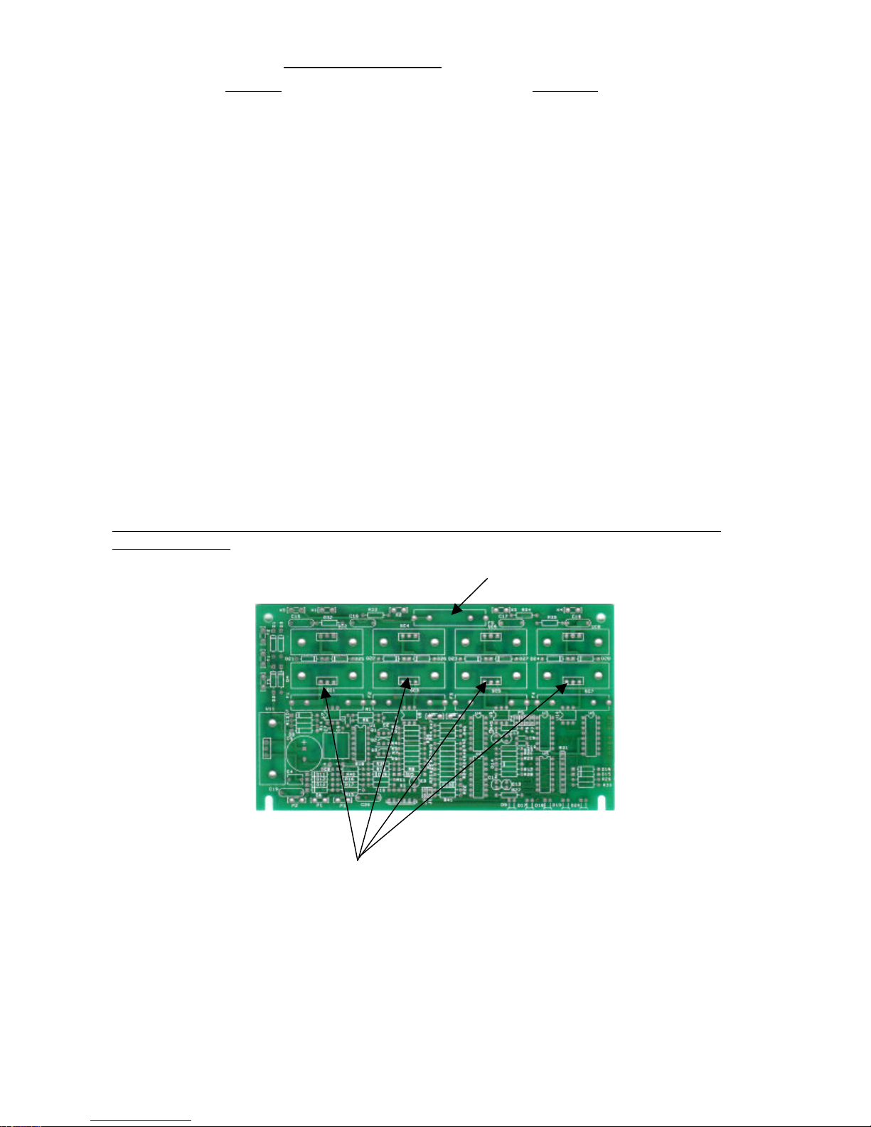
LIGHTS AND LED INDICATORS ON DIMMER
CAUTION: PLEASE DISCONNECT POWER BEFORE REMOVING COVER FOR SERVICE AS HIGH VOLTAGE IS
TROUBLESHOOTING GUIDE
SYMPTOM CHECK LIST
NO OUTPUT, LED INDICATORS SHOW 1. CHECK CHANNEL FUSES. (REFER TO
STATUS OKAY DIAGRAM BELOW)
NO POWER 1. CHECK LINE FUSE (REFER TO DIAGRAM
BELOW)
2. IF FUSE BLOWS AFTER REPLACEMENT CHECK
TRANSFORMER.
1. CHECK CHANNEL FUSES
LIGHTS ALWAYS OFF
LIGHTS ALWAYS ON
PACK FLICKER OR GLOW DIMLY.
2. CHECK FIXTURE LAMPS
3. CHECK BLACKOUT FEATURE ON CONSOLE
4. CHECK DIP SWITCH ASSIGNMENT
5. CHECK MAXIMUM DIMMER ASSIGNMENT ON
CONTROL CONSOLE
6. CHECK SOFT PATCH ON CONTROL CONSOLE
1.CHECK DIP SWITCH ASSIGNMENT
2 CHECK SIGNAL CABLE
3. CHECK OUTPUT MODE OF CONTROL CONSOLE.
1. TRANSMISSION LENGTH MAY BE A PROBLEM. GET
CONSOLE CLOSER WITH A SHORTER CABLE TO
VERIFY. REMEDY MAY BE THE USE OF 18 GAUGE
CABLE OR AN EXTERNAL POWER SUPPLY AT THE
CONSOLE. (CALL DEALER OR NSI TECHNICAL
SERVICES FOR DETAILS).
2. CHECK PRE-HEA T SETTING OF CONSOLE.
OTHERWISE PRESENT
~ STANDARD 3/10 AMP SLO BLO
LINE FUSE
CHANNEL FUSE LOCATION
REPLACE WITH VALUES AS LISTED BELOW:
ND4600 8 AMP FAST BLO, 250 VAC
ND5000 15 AMP FAST BLO, 250 VAC
IF PROBLEMS PERSIST CONTACT YOUR NEAREST NSI AUTHORIZED DEALER OR NSI TECHNICAL
SERVICES AT 800-864-2502 BETWEEN THE HOURS OF 8:00 AM TO 5:00 PM PST MONDAY THRU
FRIDAY.
Page 9 of 9
 Loading...