


CBO-750 HYBRID-R OVEN | Instructions Manual
ELECTRICAL DIAGRAM IS LOCATED BEHIND FRONT PANEL
THIS OVEN MAY BE OPERATED OUTDOORS.
ELECTRICAL DIAGRAMS ARE LOCATED BEHIND FRONT PANEL.
KEEP THIS MANUAL FOR FUTURE USE.
Chicago Brick Oven, LLC. | 205 E. Butterfield Road, #448 | Elmhurst, IL 60126
Customer Assistance: 630.359.4793
© 2016 Chicago Brick Oven. All rights reserved.

TO INSTALLER: LEAVE THESE INSTRUCTIONS WITH THE CONSUMER.
TO CONSUMER: RETAIN THESE INSTRUCTIONS FOR FUTURE USE.
WARNING!
1. DO NOT STORE OR USE GASOLINE OR OTHER FLAMMABLE LIQUIDS OR VAPORS IN THE VICINITY
OF THIS OR ANY OTHER APPLIANCE.
2. AN LP CYLINDER NOT CONNECTED FOR USE SHALL NOT BE STORED IN THE VICINITY OF THIS OR
ANY APPLIANCE.
WARNING! DO NOT USE THIS APPLIANCE UNDER EXTENDED AWNINGS.
FAILURE TO COMPLY COULD RESULT IN A FIRE OR PERSONAL INJURY.
DANGER!
IF YOU SMELL GAS:
• SHUT OFF GAS TO THE APPLIANCE.
• EXTINGUISH ANY OPEN FLAME.
• REMOVE DOOR.
• IF ODOR CONTINUES, KEEP AWAY FROM THE APPLIANCE AND IMMEDIATELY CALL YOUR GAS
SUPPLIER OR YOUR FIRE DEPARTMENT.
2

Installation
I. General
• Upon receipt of your oven, thoroughly inspect for
any damage. If damage is observed, contact the
delivery agency immediately.
• Safe and satisfactory operation of your oven
depends to a great extent on its proper
installation. Installation must conform to local
codes or in the absence of local codes, with the
National Fuel Gas Code, ANSI Z223.1/NFPA 54,
or the Natural Gas and Propane Installation Code,
CSA B149.1, as applicable.
• Keep any electrical supply cord and the fuel
supply hose away from any heated surface.
• Keep oven area free and clear from combustibles,
gasoline and other flammable vapors or liquids.
• Provide adequate clearances for air opening into
combustion chamber.
• Provide adequate clearance for servicing and
proper operation.
• The area in front of and above the oven must
be clear to avoid any obstruction of flow of
combustion and ventilation air. Means must be
provided for adequate air supply and adequate
clearance for air openings into the combustion
chamber.
• The ambiance burner is equipped with orifices
which are an integral part of the burner
assembly. The heart burner is equipped with an
orifice. Note: It is important to verify that the
orifice is properly aligned with the venturi of the
burner where gas and air enter the burner.
• For counter and freestanding installations the
oven is completely assembled as shipped. Do
not make any modifications to the oven or stand.
Any modifications can cause injury or property
damage and void warranty.
• This outdoor cooking oven shall be used
outdoors only and not to be used in a building,
garage or any other enclosed area. It is not
intended to be installed in or on boats or
recreational vehicles.
II. Clearances to Combustible and
Noncombustible Construction
Sides = 4 inch (10.2 cm) Back = 4 inch (10.2 cm)
Top = 10 inch (25.4 cm)
For use only on noncombustible floors or counters.
III. Gas Piping for Fixed Gas Supply
• Connect oven to gas supply line. Under no
circumstances should the gas supply line be
smaller than the inlet pipe on the oven. Use pipe
sealant on all joints. Sealant must be resistant to
the action of LP gases.
• A 1/8-inch (3.175 mm) pressure tap is provided
on the gas control for checking the gas pressure.
The gas control is equipped with a pressure
regulator. The outlet pressure setting is 4-inch
(101.6 mm) water column on natural gas and 10inch (254 mm) water column on propane gas.
• Level oven and its individual shut-off valve must
be disconnected from the gas supply piping
system during any pressure testing of the system
at test pressures in excess of ½ psig (3.45kPa).
• The oven must be isolated from the gas supply
piping system by closing the individual manual
shut-off valve during any pressure testing of the
gas supply piping system at test pressures equal
to or less than ½ psig (3.45kPa).
To check for leaks, use a soap and water solution.
DO NOT USE OPEN FLAME
3

Installation Continued
IV. Information for Use with a Self Contained LP-Gas Supply System
DO NOT STORE A SPARE LP GAS CYLINDER UNDER OR
NEAR THIS APPLIANCE.
NEVER FILL THE CYLINDER BEYOND 80% FULL. IF
THESE TWO STATEMENTS ARE NOT FOLLOWED
EXACTLY, A FIRE CAUSING DEATH OR SERIOUS
INJURY MAY OCCUR.
• If your oven is factory-built for LP (Propane)
the regulator supplied is set for 11" W.C. and is
for use with LP gas only. The factory-supplied
regulator and hose must be used with a 20 LB LP
cylinder.
• The LP-gas supply cylinder must be constructed
and marked in accordance with the Specifications
for LP-gas Cylinders of the U.S. Department of
Transportation (D.O.T.) or the National Standards
of Canada CAN/CSA-B339, Cylinders, Spheres
and Tubes for the Transportation of Dangerous
Goods, and Commission, as applicable; and
Locate and orient the LP cylinder to provide proper
vapor withdrawal. Connect the regulator to the
LP cylinder. Hand tighten it. Do not use a wrench.
Check for leaks using a soapy water solution.
NEVER USE OPEN FLAME TO CHECK FOR GAS
LEAK.
Note: Any 20 LB LPG cylinder can be used provided it
is compatible with the retention means as shown in
photo.
• If the oven is not in use, the gas must be turned
“OFF” at the supply cylinder. The cylinder must be
disconnected from the oven and stored outdoors,
out of the reach of children and must not be stored
in building, garage or any other enclosed area.
• Always inspect the hose before each use of the
oven. If it is evident there is excessive abrasion or
wear, or the hose is cut, it must be replaced prior to
the oven being put in operation. The replacement
hose assembly shall be that specified by the
manufacturer.
1. Provided with a listed overfilling prevention
device
2. Provided with a cylinder connection device
compatible with the connection for outdoor
cooking appliances
3. Marked with a 20 LB LPG capacity
It must be provided with a shut-off valve terminating
in gas tank valve outlet. It must include a collar
to protect the cylinder valve. The cylinder supply
system must be arranged for vapor withdrawal.
• Install the factory-supplied hose and regulator
assembly as shown in illustration. Connect the
3/8" flare end of the hose to the oven piping
outlet coupling using a ¾" open wrench. Do not
apply pipe sealant to the ¾" flare connection.
The pressure regulator and hose assembly supplied
with to the oven must be used. Replacement of
pressure regulator and hose assembly must be those
specified by the oven manufacturer.
4

Installation Continued
VIII. Electrical Connections
When installed, the oven must be electrically
grounded in accordance with local codes or in the
absence of local codes, with the National Electrical
Code, ANSI/NFPA 70, or the Canadian Electrical Code
Part 1, CSA C22.1.
Electrical Rating
Volts Amps Frequency
120 1.50 60
• To protect against electric shock, do not immerse
cord or plugs in water or other liquid;
• Unplug from the outlet when not in use and before
cleaning. Allow to cool before putting on or taking
off parts;
• Do not operate any outdoor cooking gas appliance
with a damaged cord, plug, or after the appliance
malfunctions or has been damaged in any manner.
Contact the manufacturer for repair;
• Do not let the cord hang over the edge of a table or
touch hot surfaces;
• Do not use an outdoor cooking gas appliance for
purposes other than intended;
• When connecting, first connect plug to the outdoor
cooking gas appliance then plug appliance into
the outlet;
• Use only a Ground Fault Interrupter (GFI) protected
circuit with this outdoor cooking gas appliance;
• Never remove the grounding plug or use with an
adapter of 2 prongs; and
• Use only extension cords with 3-prong grounding
plug, rated for the power of the equipment, and
approved for outdoor use with a W-A marking.
ELECTRICAL DIAGR AM IS LOCATED BEHIND FRONT PANEL
VI. Hearth Burner Lighting Instructions
READ INSTRUCTIONS BEFORE LIGHTING
1. Set main gas supply cock in “OFF” position.
2. Turn main electrical supply “OFF.”
3. Wait at least (5) five minutes.
4. Set temperature control to desired settings
5

Installation Continued
5. Place ambiance burner “ON/OFF” switch in
“OFF” position.
6. Set main gas supply cock in “ON” position.
7. Turn main electrical supply “ON.”
8. Place main “ON/OFF” switch in “ON” position.
9. If burner does not light, repeat steps 1-8.
VII. Ambiance Burner Lighting
Instructions
Note: The hearth burner system must be ON as controlled by the
thermostat.
Place ambiance burner ON/OFF switch in “ON” position.
VIII. Shutting Down Instructions
To shut down the burner control systems for a period
of time, turn “OFF” the main electrical supply and place
the main panel ON/OFF switch and ambiance burner
circuit ON/OFF switch to the “OFF” position.
To shut down the burner control systems for longer than
a week, turn “OFF” and “LOCK OUT” the main electrical
supply to the burner systems and turn “OFF” and “LOCK
OUT” the incoming gas supply gas cock.
6

Operation
IX. CAUTION: In the event of power
failure, do not attempt to operate oven
until power is resumed.
NOTE: Inspect the gas hose (if used) before each use of the oven.
If it is evident there is excessive abrasion or wear, or
the hose is cut, it must be replaced prior to the oven
being put in operation. The replacement hose assembly
shall be that specified by the manufacturer.
Lighting & Shutting down Instructions: Refer to
related section in Installation portion of this manual and
label located on oven front panel.
To cure the oven on first firing and release the moisture
from the oven dome, the thermostat should be set at
approximately 212ºF (100ºC) over a period of 2-3 days.
Curing the oven can be done with only the ambiance
burner turned “ON”. Use one tank of propane or get the
oven to 250ºF (121ºC) for 16 hours in duration. This can
be split into two different 8-hour time periods.
Note: Due to thermal expansion, small cracks may
appear in the dome or hearth during the curing process.
This is normal and the quality of your oven will not be
compromised.
This oven can be operated as a gas oven or as a hybrid
oven:
• For gas operation, follow Lighting & Shutting down
Instructions.
• For hybrid operation, wood can be inserted on the
cooking surface after oven temperature reaches
thermostat setting.
Note: Use only small amounts of wood to enhance the
flavor of foods. NEVER place wood on top of or direct
contact with the ambiance burner at the back of the
oven.
Do not cook with the door closed. All cooking should be
done with the door open.
WARNING
NEVER COVER SLOTS, HOLES, OR PASSAGES IN THE OVEN BOTTOM OR COVER THE ENTIRE DECK WITH MATERIAL
SUCH AS ALUMINUM FOIL.
DOING SO BLOCKS AIR FLOW THROUGH THE OVEN AND MAY CAUSE CARBON MONOXIDE POISONING.
ALUMINUM FOIL LININGS MAY TRAP HEAT CAUSING A FIRE HAZARD.
7
Maintenance
X. CAUTION: Oven must be “OFF” and
cool before any cleaning is done.
Disconnect the power supply to the appliance before
cleaning and servicing the oven.
• Clean the oven cooking surface after each use with
a cleaning brush.
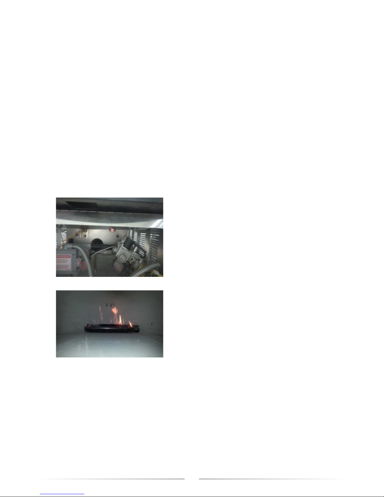
• Periodically check and clean hearth burner venturi
tube for insects and insect nests.
A CLOGGED VENTURI TUBE CAN LEAD TO A FIRE
INSIDE THE OVEN
• For service and repairs, contact factory, factory
representative or local service company.
• All maintenance and/or repair MUST be performed
by someone trained/qualified to work on gas/
electrical equipment. For additional information or
assistance, contact Chicago Brick Oven Customer
Assistance at 630.359.4793
• In dirty/dusty/wet atmospheres, it may be necessary
to examine/perform maintenance at additional times
depending on the burner packages’ usage.
• Visually check burner flames for proper operation.
• Keep outdoor oven area clear and free from
combustible materials, gasoline and other flammable
vapors and liquids.
• Do not obstruct the flow of combustion and
ventilation air.
• Keep the ventilation openings of the cylinder
enclosure free and clear from debris.
8

chicagobrickoven.com
Chicago Brick Oven, LLC. | 205 E. Butterfield Road, #448 | Elmhurst, IL 60126
Customer Assistance: 630.359.4793
© 2016 Chicago Brick Oven. All rights reserved.
 Loading...