

NSC LM9073SX, LM9073S Datasheet
LM9073
Dual High Current Low-Dropout System Regulator
General Description
The LM9073 is a high performance voltage regulator system
with operational and protection features that address many
requirements of automotive applications. Two regulated outputs are provided. The main regulator provides a precision
2% tolerance 5V outputat700mAwith a low dropoutcharacteristic. The second output, an External Supply regulator,
provides a 5V output with 2% tolerance for load currents up
to 100mA. ThisExternal Supply output is fully protected from
short circuit to ground or the unregulated input supply (ignition or battery potentials in automotive applications) which
makes it suitable for powering remotely located load circuits
or sub-systems.
The LM9073 also contains a programmable delayed system
reset output.Two control inputs areprovided. An ON/OFF input intended for connection to an ignition switch, and a Keep
Alive input whereby a system can remain powered after ignition has been switched OFF. Additionally, a watchdog function is built in to enhance system operationally reliability.
For EMC concerns the LM9073 remains fully operational
and does not generate false rest signals while subjected to
greater than 100mA, 1MHz to 400MHz bulk current injection
signals on the input supply and External Supply output lines.
Features
n Two 5V regulated outputs:
n 700mA, 2% Main output
n 100mA, 2% External Supply output
n External Supply output protected from shorts to battery
n Good EMI (1MHz to 400MHz, BCI) immunity
n Separate ON/OFF and Keep-Alive control inputs
n Less than 100µA quiescent current in OFF state
n Programmable delayed reset output
n Adjustable threshold voltage for generating reset
n Built-in system watchdog timer
n Input transient protection over 60V to −45V
n Less than 1V dropout at full load
n Wide −40˚C to 125˚C operating temperature range
n Surface mount, TO−263 and standard TO−220 power
packages
Applications
n Automotive module supply power conditioning
n Remote sub−system powering
n Continuous operation for save routines and E
2
PROM
programing after power down command
n Safety relates systems − EMC operational with a system
watchdog monitor
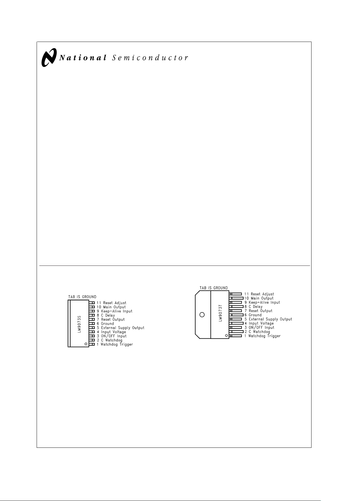
Connection Diagram
11 Lead TO−263 Package
DS101296-1
Top View
Order Number LM9073S
See NS Package Number TS11B
11 Lead TO−220 Package
DS101296-2
Top View
Order Number LM9073T
See NS Package Number TA11B
PRELIMINARY
April 2000
LM9073 Dual High Current Low-Dropout System Regulator
© 2000 National Semiconductor Corporation DS101296 www.national.com
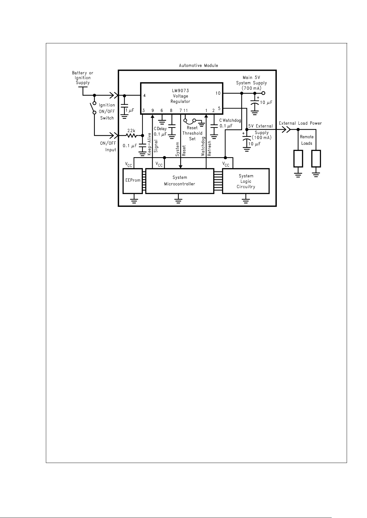
Block Diagram
DS101296-3
LM9073
www.national.com 2
Absolute Maximum Ratings (Note 1)
If Military/Aerospace specified devices are required,
please contact the National Semiconductor Sales Office/
Distributors for availability and specifications.
Input Voltage −45V to 45V
Input Voltage (transient, t≤400mS) 60V
Forced Output Voltages
Main Output −0.3V to 7V
External Supply Output −0.3V to 27V
ON/OFF Input Voltage(Note 6) −0.3V to 16V
ON/OFF Input Current
±
20mA
Keep Alive In, Reset Out, C
DELAY
,
Reset Adjust,Watchdog Trigger
In, C Watchdog −0.3V to 7V
Junction Temperature 150˚C
Storage Temperature −65˚C to 150˚C
ESD Susceptibility(Note 2) 2000V
Lead temperature (Soldering, 10 Sec) 265˚C
Operating Ratings(Note 1)
Input Voltage Range 6V to 27V
Ambient Temperature Range −40˚C to 125˚C
Thermal Resistance
θ
JC
4˚C/W
θ
JA
43˚C/W
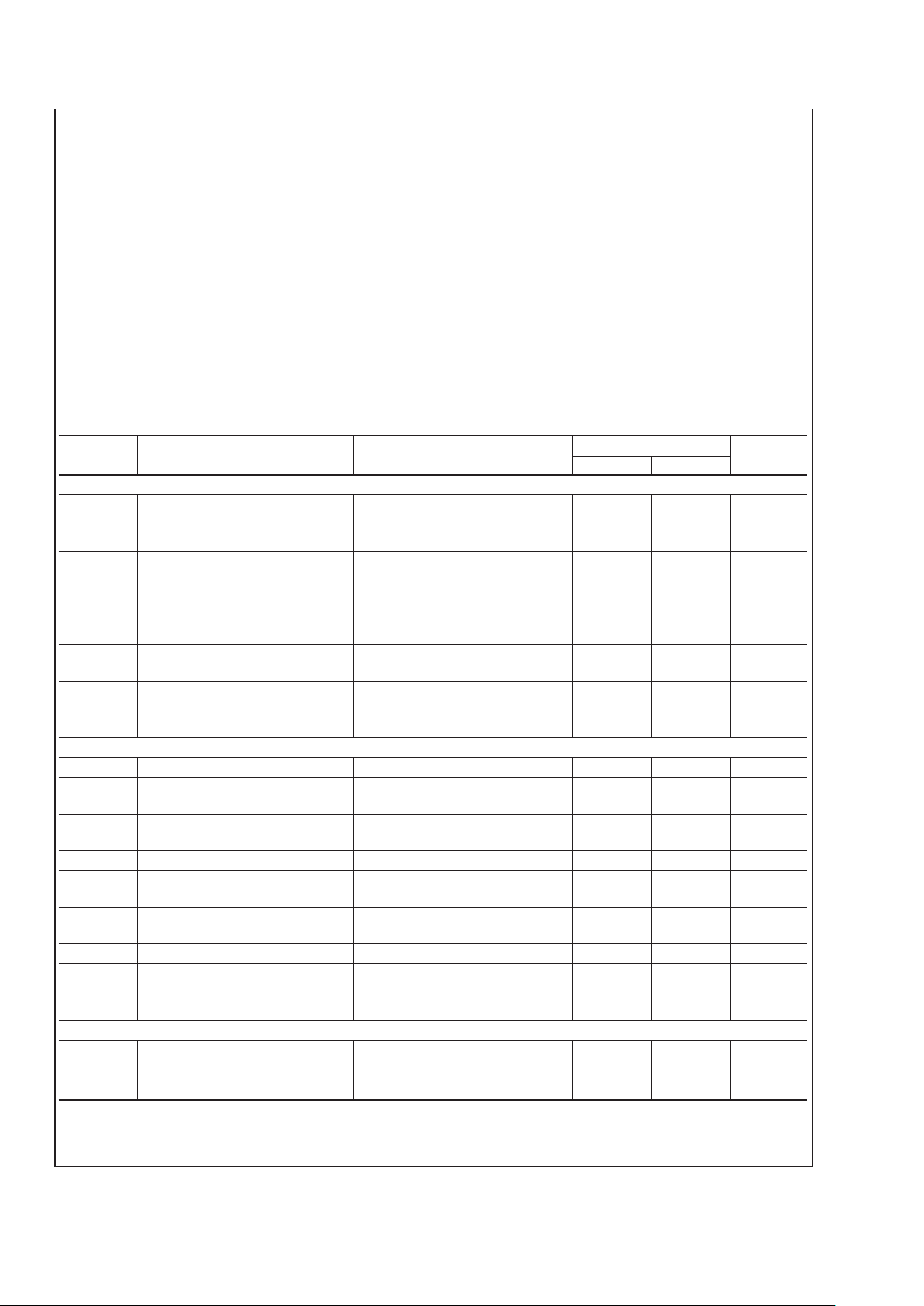
Electrical Characteristics
The following specifications apply for 6V ≤ vIN≤ 19V, t
CASE
= 25˚C unless otherwise specified. C
OUT
≥ 6µF with 0.3Ω≤ESR
≤ 0.3Ω on each regulator output.
Symbol Parameter Conditions
LM9073
Units
Min Max
MAIN REGULATOR
V
MAIN
Output Voltage
10mA ≤ I
LOAD
≤ 700mA 4.9 5.1 V
19V ≤ V
IN
≤ VSD,
5mA ≤ I
LOAD
≤ 700mA
4.8 5.2 V
R
MLOAD
Load Regulation
V
IN
= 16V, 10mA ≤ I
LOAD
≤
700mA
25 mV
R
MLINE
Line Regulation I
LOAD
= 700mA, 8V ≤ VIN≤ 16V 25 mV
V
MDO
Dropout Voltage, VIN−V
MAIN
V
IN
>
5.5V, 10mA ≤ I
LOAD
≤
700mA(Note 5)
1V
V
SD
Overvoltage Shutdown
Threshold
30 36 V
I
MSC
Output Short Circuit Current RL=1Ω 2000 mA
PSRR Ripple Rejection
V
IN
= 9V, 50Hz ≤ freq ≤ 20kHZ,
V
RIPPLE
=4V
P−P
40 dB
External Supply Regulator
V
EXT
Output Voltage 3mA ≤ I
LOAD
≤ 100mA 4.9 5.1 V
19V ≤ V
IN
≤ V
SD
3mA ≤ I
LOAD
≤ 100mA
4.8 5.2 V
R
ELOAD
Load Regulation
V
IN
= 16V, 3mA ≤ I
LOAD
≤
100mA
25 mV
R
ELINE
Line Regulation I
LOAD
= 100mA, 8V ≤ VIN≤ 16V 25 mV
V
EDO
Dropout voltage, VIN−V
EXT
V
IN
>
5.5V, 3mA ≤ I
LOAD
≤
100mA (Note 5)
0.8 V
V
SD
Overvoltage Shutdown
Threshold
30 36 V
I
ESC
Output Short Circuit Current RL=1Ω 250 mA
V
ESC
Output Short Circuit No effect on other functions −0.3 27 V
PSRR Ripple Rejection
V
IN
= 9V, 50Hz ≤ freq ≤ 20kHZ,
V
RIPPLE
=4V
PP
40 dB
Input Current
I
QOFF
Quiescent Input Current with
Both Regulators OFF.
8V ≤ V
IN
≤ 16V 100 µA
16V ≤ V
IN
≤ 42V 10 mA
I
Q
No Load Quiescent Current 8V ≤ VIN≤ 19V, IL= 0mA 15 mA
LM9073
www.national.com3
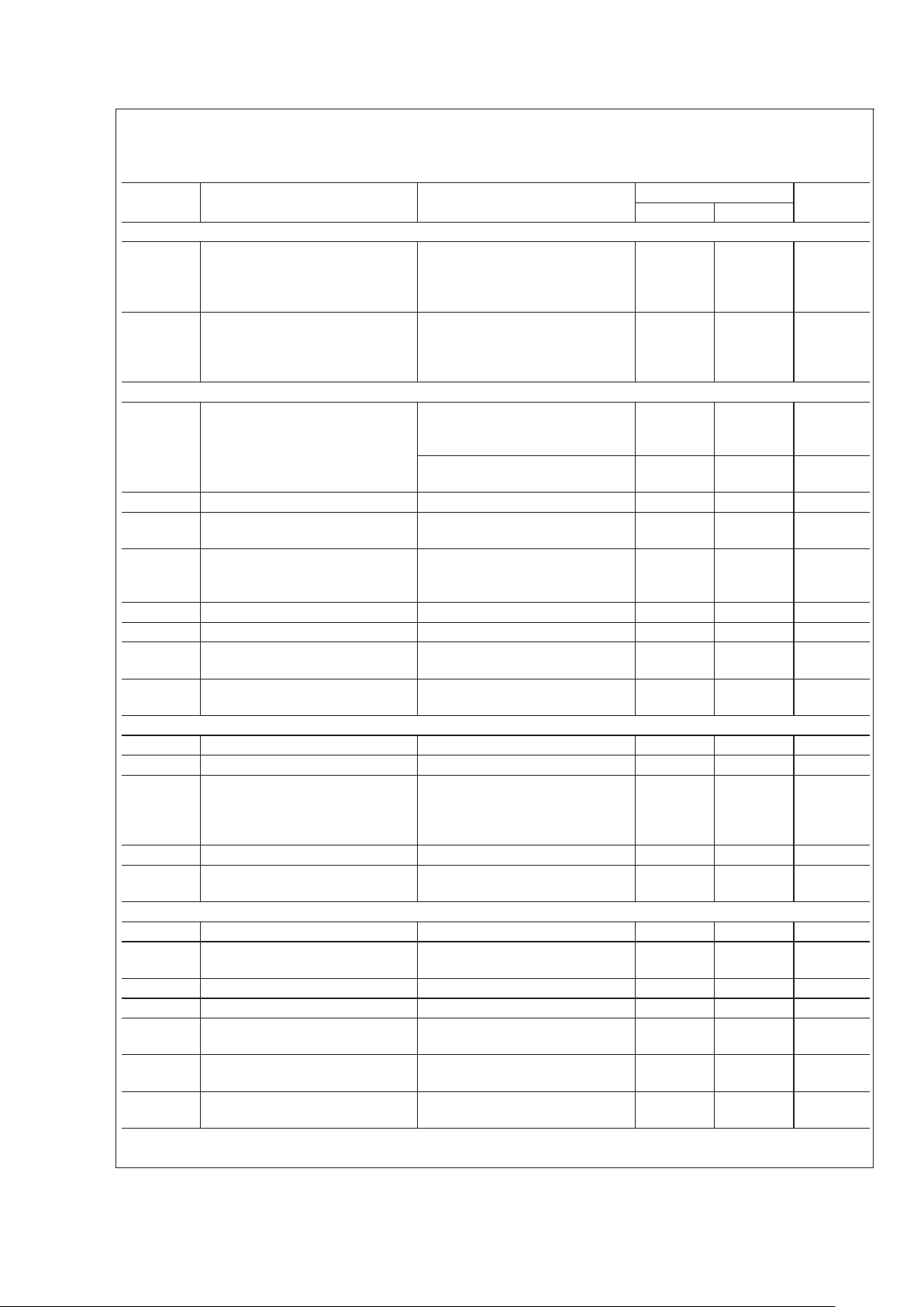
Electrical Characteristics (Continued)
The following specifications apply for 6V ≤ vIN≤ 19V, t
CASE
= 25˚C unless otherwise specified. C
OUT
≥ 6µF with 0.3Ω≤ESR
≤ 0.3Ω on each regulator output.
Symbol Parameter Conditions
LM9073
Units
Min Max
Input Current
IN
ON
Additional Input Current with
both Regulators ON
V
IN
≥ 8V, I
LTOTAL=IMAIN
+
I
LEXT
I
LTOTAL
= 700mA + 100mA =
800mA
1.2
X
I
LTOTAL
LIN
DO
Additional Input Current when in
Dropout
0V
<
V
IN
<
8V, (Note 4)
I
LTOTAL=IMAIN+ILEXT
I
LTOTAL
= 700mA + 100mA =
800mA
1.5
X
I
LTOTAL
Reset Output
V
THRL
Low Switching Threshold
V
MAIN
output controls Reset
Reset Adjust (pin 11 )open
circuited
4.0 4.2 V
Reset Adjust (pin 11) shorted to
ground
4.5 4.7 V
V
THRH
High Switching Threshold V
MAIN
output controls Reset 5.35 5.75 V
V
LOW
Logic Low Output Threshold
1V ≤ V
MAIN
≤ V
THRL
R
RESET
= 50kΩ to V
MAIN
0.4 V
V
HIGH
Logic High Output Threshold
Normal opeation,
V
THRL
≤ V
MAIN≤THRH
,, I
SOURCE
=0
V
MAIN
−50mV
V
MAIN
V
R
P−U
Internal Pull-Up Resistance 2.4 6.0 kΩ
T
DELAY
Reset Delay Interval C
DELAY
= 0.1µF 35 70 mS
T
RISE
Output Rise Time
From 10% V
MAIN
to 90% V
MAIN
C
LRESET
= 50pF
1.5 µS
T
FALL
Output Fall Time
From 90% V
MAIN
to 10% V
MAIN
C
LRESET
= 50pF
0.5 µS
Watchdog
V
TRIGL
Trigger Input Logic Low Voltage .08 V
V
TRIGR
Trigger Input Logic High Level 2 V
T
WD
Watchdog Refresh Window
C
WATCHDOG
= 0.1µF (low
leakage)
I
WATCHDOG
for charging the
watchdog
35 70 mS
T
PW
Watchdog Trigger Pulse Width 10 µS
R
TRIG
Trigger Input Pull-down
Resistance
540kΩ
Control Inputs
V
ON
ON Threshold for ON/OFF Input Rseries = 22kΩ 3.5 4.5 V
V
OFF
OFF Threshold for ON/OFF
Inpu
Rseries = 22kΩ (Note 3) 1.5 2.5 V
I
ON/OFF
ON/OFF Input Current 1.4V ≤ V
ON/OFF
≤ 4.5V 1 12 µA
−0.3V ≤ V
ON/OFF
≤ 7V(Note 6) −1 5 mA
ON
K−A
Turn ON Threshold for Keep
Alive Input
2V
OFF
K−A
Turn OFF Threshold for Keep
Alive Input
(Note 3) 0.8 V
R
P−D
Pull−Down Resistance at Keep
Alive Input
0V ≤ V
K−A
≤ 5V 5 40 kΩ
LM9073
www.national.com 4
Electrical Characteristics (Continued)
Note 1:
“Absolute Maximum Ratings”
indicate limits beyond which damage to the device may occur.
“Operating Ratings”
indicate conditions for which the device is
functional, but donot guaranteespecific performance limits.
“Electrical Characteristics”
state DC andAC electrical specificationsunder particulartest conditions which
guarantee specificperformance limits. This assumes that the device is within theOperating Ratings. Specifications are not guaranteed for parameters where no limit
is given, however, the typical value is a good indication of device performance.
Note 2: Human body model, 150 pFcapacitor discharged through a 1.5 kΩ resistor.
Note 3: If either control input is left open circuited the regulators will turn OFF.
Note 4: The input quiescent current will increase when the regulators are in dropout conditions. The amount of additional input current is a direct function of the to
a load current on both outputs. The peak increase in current is limited to 50% of the total load current.
Note 5: The dropoutvoltage specifications actually indicate the saturation voltage of the PNP power transistors used in eachregulator. Over the full load current and
temperature ranges the Main regulator will output at least 4.5V and the External Supply regulator at lease 4.7V with an input voltage of only 5.5V
Note 6: The ON/OFF input is internally clamped to a 7V zener diode through a 1KΩ resistor.
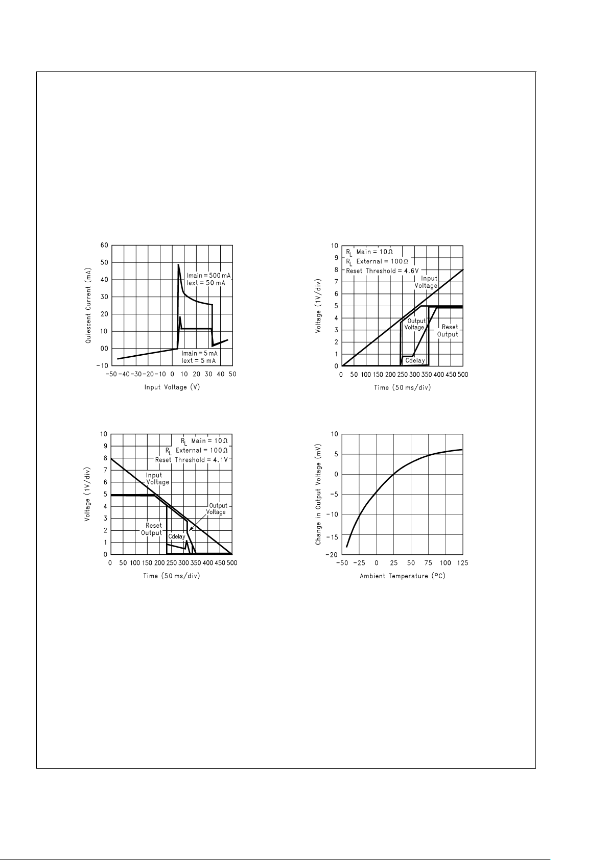
Quiescent Input Current vs. Input Voltage
DS101296-4
Turn-On Characteristic
DS101296-5
Turn-Off Characteristic
DS101296-6
Normalized Output Voltages vs Temperature
DS101296-7
LM9073
www.national.com5
Electrical Characteristics (Continued)
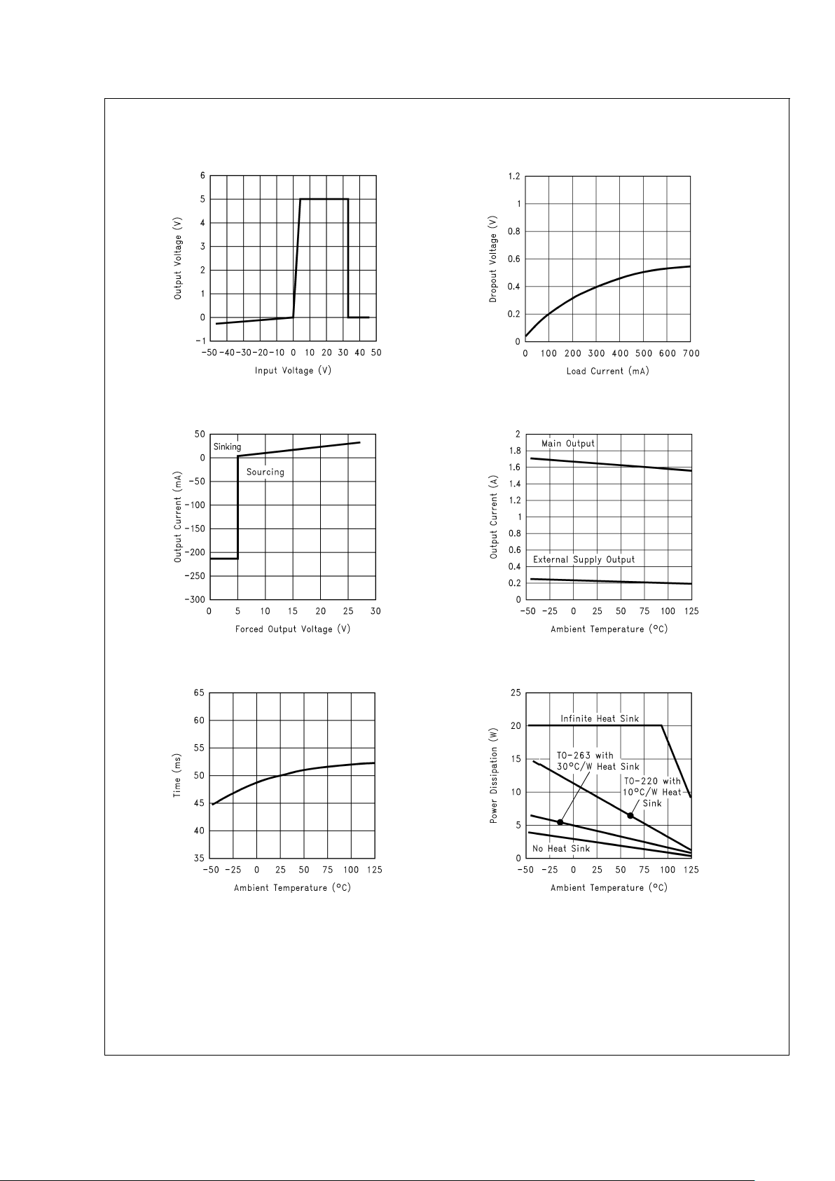
Output Voltages at Input Voltage Extremes
DS101296-8
Main Output Dropout Voltage vs Load Current
DS101296-9
External Supply Output Short Circuit Current
DS101296-10
Output Short Circuit Current vs Temperature
DS101296-11
Watchdog and Reset Delay Time vs Temperature
DS101296-12
Maximum Power Dissipation
DS101296-13
LM9073
www.national.com 6
 Loading...