

NSC LM9072SX, LM9072S Datasheet
LM9072
Dual Tracking Low-Dropout System Regulator
General Description
The LM9072 is a high performance voltage regulator system
with operational and protection features that address many
requirements of automotive applications. Two regulated outputs are provided. The main regulator provides a precision
2%maximum tolerance5Voutputat 350 mA witha low dropout characteristic. The second regulator provides a 5V output that tracks the main regulator output voltage within 1.5
%
with load currents up to 80 mA. The tracking output is ideal
for use in powering remotely located sensors with outputs
that are ratiometric to the main system supply. This output is
fully protected from short circuits to ground or the unregulated input supply (ignition or battery potentials in automotive
applications).
The LM9072 also contains a programmable delayed system
reset output.Two control inputs are provided. An ON/OFF input intended for connection to an ignition switch, and a Keep
Alive input to allow a system to remain powered after ignition
has been switched OFF.
For EMC concerns the LM9072 remains fully operational
and does not generate false rest signals while subjected to,
1 MHz to 400 MHz bulk current injection signals greater than
100 mA on the input supply and tracking output lines.
Features
n Two 5V regulated outputs:
— 350 mA, 2%Main output
— 80 mA, 1.5%Tracking output
n Good EMI (1 MHz to 400 MHz, BCI) immunity
n Separate ON/OFF and Keep-Alive control inputs
n Less than 100 µA quiescent current in OFF state
n Programmable delayed reset output
n Input transient protection over 60V to −45V
n Tracking output protected from shorts to battery
n Less than 1V dropout at full load
n −40˚C to +125˚C operating temperature range
n Surface mount TO-263 Power Package and Standard
TO-220 power package
Typical Applications
n Automotive module supply power conditioning
n Remote sensor biasing
n Ratiometric to supply sensor detection
n Continuous operation for save routines and EPROM
programming after power down command
n Safety related systems— EMC operational
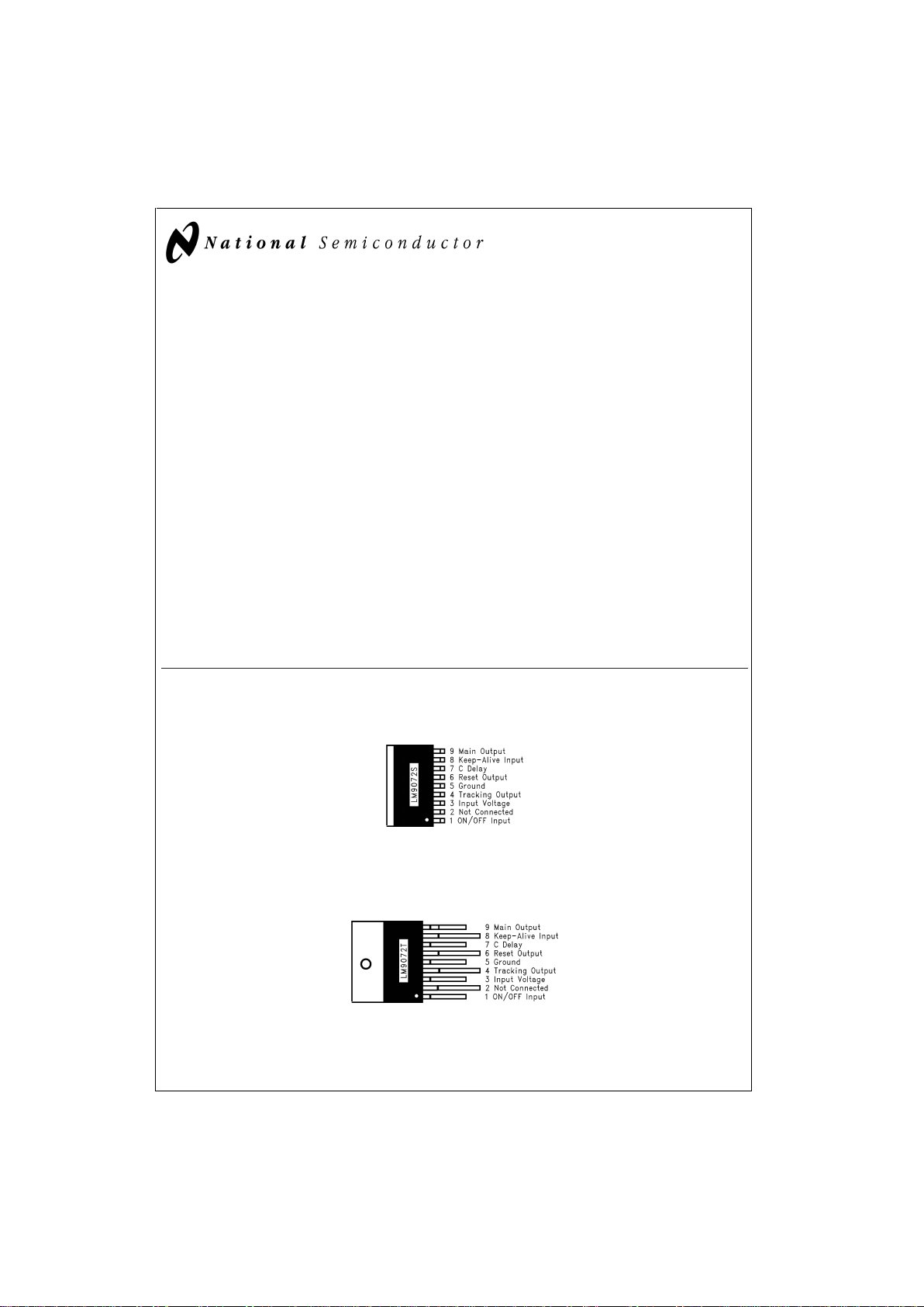
Connection Diagrams and Ordering Information
9-Lead TO-263
Surface Mount Power Package
DS012906-2
Backside metal is internally connected to ground.
Order Number LM9072S
See NS Package Number TS9A
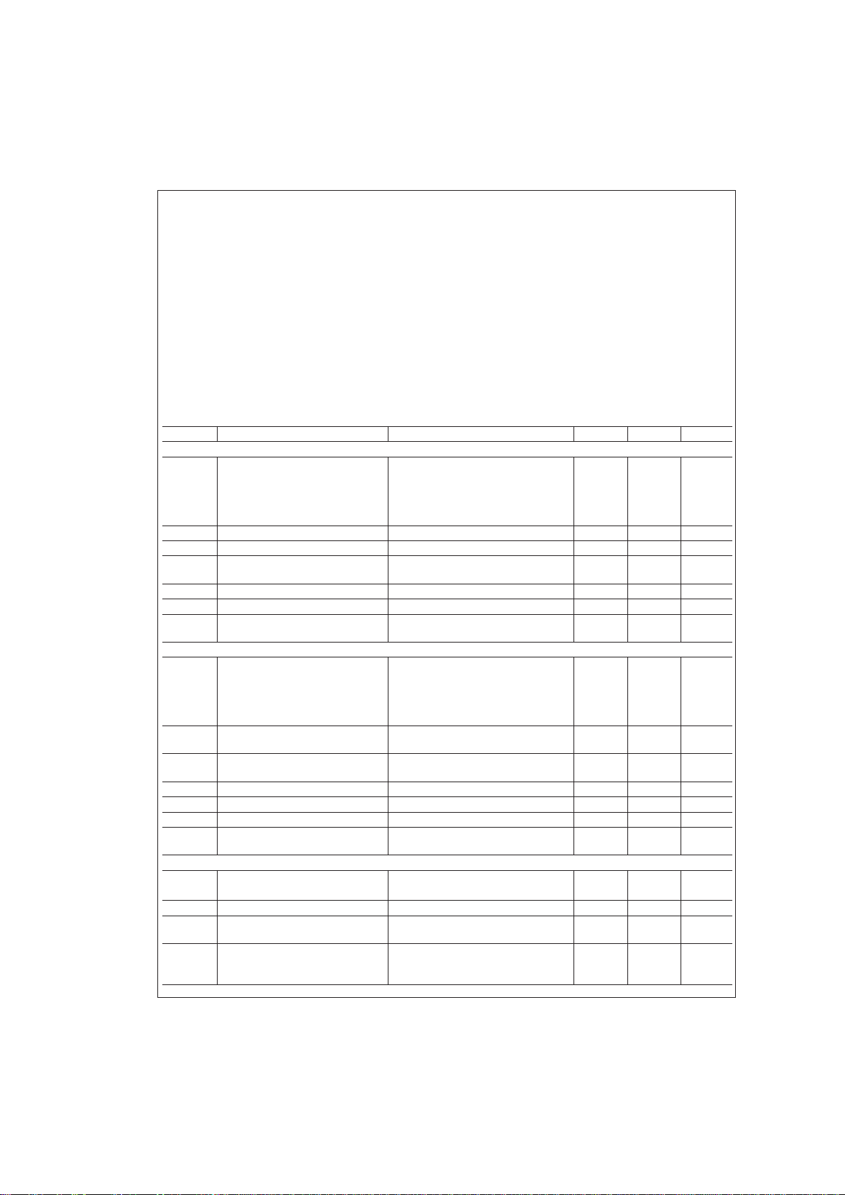
9-Lead TO-220 Package
DS012906-3
Tab is internally connected to ground.
Order Number LM9072T
See NS Package Number TA9A
December 1999
LM9072 Dual Tracking Low-Dropout System Regulator
© 1999 National Semiconductor Corporation DS012906 www.national.com
Absolute Maximum Ratings (Note 1)
If Military/Aerospace specified devices are required,
please contact the National Semiconductor Sales Office/
Distributors for availability and specifications.
Input Voltage (Continuous) −45V to 45V
Input Voltage (Transient, t ≤ 400 ms) 60V
Forced Output Voltages
Main Output −0.3V to 7V
Tracking Output −0.3V to 27V
ON/OFF Input Voltage (Note 6) −0.3V to 16V
ON/OFF Input Current
±
20 mA
Keep Alive In, Reset Out,
C
DELAY
Voltage −0.3V to 7V
Junction Temperature 150˚C
Storage Temperature Range −65˚C to +150˚C
ESD Susceptibility (Note 2) 2000V
Lead Temperature
(Soldering, 10 seconds) 265˚C
Operating Ratings (Note 1)
Input Voltage Range 6V to 27V
Ambient Temperature Range −40˚C to +125˚C
Thermal Resistance, θ
J-C
4˚C/W
Thermal Resistance, θ
J-A
43˚C/W
Electrical Characteristics
6.0V ≤ VIN≤ 19V, T
CASE
=
25˚C, unless otherwise specified. C
OUT
≥ 6 µF with 0.3Ω≤ESR ≤ 3Ω on each regulator output.
Symbol Parameter Conditions Min Max Units
MAIN REGULATOR
V
MAIN
Output Voltage 5 mA ≤ I
LOAD
≤ 350 mA
−40˚C ≤ T
CASE
≤ 125˚C
4.9 5.1 V
19V ≤ V
IN
≤ VSD,
5mA≤I
LOAD
≤ 350 mA
−40˚C ≤ T
CASE
≤ 125˚C
4.8 5.2 V
R
MLOAD
Load Regulation V
IN
=
16V, 5 mA ≤ I
LOAD
≤ 350 mA 25 mV
R
MLINE
Line Regulation I
LOAD
=
350 mA, 8V ≤ V
IN
≤ 16V 25 mV
V
MDO
Dropout Voltage, VIN–V
MAIN
V
IN
>
5.5V, 5 mA ≤ I
LOAD
≤ 350 mA
(Note 5)
0.8 V
V
SD
Overvoltage Shutdown Threshold 30 36 V
I
MSC
Output Short Circuit Current R
L
=
1Ω 450 1000 mA
R
MRR
Ripple Rejection V
IN
=
9V, 50 ≤ Freq ≤ 20 kHz,
V
RIPPLE
=
4V
P-P
40 dB
TRACKING REGULATOR
V
TRACK
Output Voltage 1 mA ≤ I
LOAD
≤ 80 mA
−40˚C ≤ T
CASE
≤ 125˚C
4.85 5.15 V
19V ≤ V
IN
≤ V
SD
1mA≤I
LOAD
≤ 80 mA
−40˚C ≤ T
CASE
≤ 125˚C
4.725 5.275 V
V
ERROR
Output Tracking Error
(V
MAIN–VTRACK
)
1mA≤I
LOAD
≤ 80 mA
−50 50 mV
V
TDO
Dropout Voltage,
V
IN–VTRACK
V
IN
>
5.5V, 1 mA ≤ I
LOAD
≤ 80 mA
(Note 5)
0.8 V
V
SD
Overvoltage Shutdown Threshold 30 36 V
I
TSC
Output Short Circuit Current R
L
=
1Ω 200 mA
V
TSC
Output Short Circuit Voltage No Effect On Other Functions −2 27 V
R
TRR
Ripple Rejection V
IN
=
9V, 50 ≤ Freq ≤ 20 kHz,
V
RIPPLE
=
4V
P-P
40 dB
INPUT CURRENT
I
qOFF
Quiescent Input Current with
Both Regulators OFF
8V ≤ VIN≤ 16V 40 µA
16V ≤ V
IN
≤ 42V 10 mA
I
q
No Load Quiescent Current 8V ≤ VIN≤ 19V, I
L
=
0mA 15 mA
In
ON
Additional Input Current with
Both Regulators ON
V
IN
>
8V, I
Ltotal
=
I
Lmain+ILtrack
I
Ltotal
=
350mA+80mA=430 mA
1.2 x I
Ltotal
Iin
do
Additional Input Current in Dropout 0V<V
IN
<
8V, (Note 4)
I
Ltotal
=
I
Lmain+ILtrack
I
Ltotal
=
350mA+80mA=430 mA
1.5 x I
Ltotal
LM9072
www.national.com 2
Electrical Characteristics (Continued)
6.0V ≤ VIN≤ 19V, T
CASE
=
25˚C, unless otherwise specified. C
OUT
≥ 6 µF with 0.3Ω≤ESR ≤ 3Ω on each regulator output.
Symbol Parameter Conditions Min Max Units
RESET OUTPUT
V
THRL
Low Switching Threshold V
MAIN
Output Controls Reset 4.45 4.75 V
V
THRH
High Switching Threshold V
MAIN
Output Controls Reset 5.40 5.75 V
V
LOW
Logic Low Output Voltage 1V ≤ V
MAIN
≤ V
THRL
,
R
RESET
=
50 kΩ to V
MAIN
0.4 V
V
HIGH
Logic High Output Voltage Normal Operation,
V
THRL
≤ V
MAIN
≤ V
THRH,ISOURCE
=
0
V
MAIN
–
50 mV
V
MAIN
V
R
P-U
Internal Output Pull-Up Resistance 2.4 6.0 kΩ
T
DELAY
Reset Delay Interval C
DELAY
=
0.1 µF (Low Leakage),
I
DELAY
for Charging the Delay
Capacitor is Typically 6 µA
35 70 ms
T
RISE
Output Rise Time From 10%V
MAIN
to 90%V
MAIN
C
LRESET
=
50 pF
1.5 µs
T
FALL
Output Fall Time From 90%V
MAIN
to 10%V
MAIN
C
LRESET
=
50 pF
0.5 µs
CONTROL INPUTS
V
ON
ON Threshold for ON/OFF Input R
SERIES
=
22 kΩ 3.5 4.5 V
V
OFF
OFF Threshold for ON/OFF Input R
SERIES
=
22 kΩ (Note 3) 1.5 2.5 V
I
ON/OFF
ON/OFF Input Current 1.4V ≤ V
ON/OFF
≤ 4.5V 1 12 µA
−0.3V ≤ V
ON/OFF
≤ 7V (Note 6) −1 5 mA
ON
K-A
Turn ON Threshold for Keep Alive
Input
2V
OFF
K-A
Turn OFF Threshold for Keep Alive
Input
(Note 3)
0.8 V
R
P-D
Pull-Down Resistance at Keep
Alive Input
0V ≤ V
K-A
≤ 5V
540kΩ
Note 1: Absolute Maximum Ratings indicate limits beyond which damage to the device may occur. Operating Ratings indicate conditions for which the device remains functional but do not guarantee specific performance limits. For guaranteed specifications and test conditions see the Electrical Characteristics.
Note 2: Human body model, 150 pF capacitor discharged through a 1.5 kΩ resistor.
Note 3: If either control input is left open circuited the regulators will turn OFF.
Note 4: The input quiescentcurrent will increase when the regulators are in dropout conditions. The amount of additional input currents is a direct function of the total
load current on both outputs. The peak increase in current is limited to 50%of the total load current.
Note 5: The dropout voltage specifications actually indicate the saturation voltage of the PNP power transistors used in each regulator. Over the full load current and
temperature ranges both regulators will output at least 4.7V with an input voltage of only 5.5V.
Note 6: The ON/OFF input is internally clamped to a 7V zener diode througha1kΩresistor.
LM9072
www.national.com3
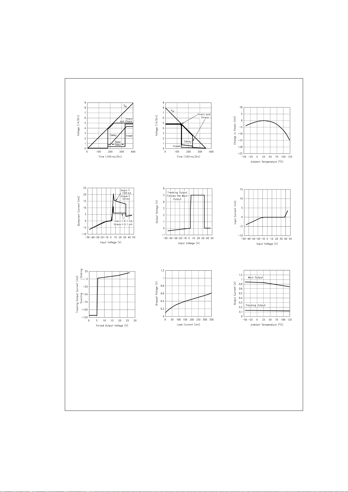
Typical Performance Characteristics (T
A
=
25˚C unless otherwise specified)
Turn-ON Characteristic
DS012906-4
Turn-OFF Characteristic
DS012906-5
Normalized Main Output
Voltage vs Temperature
DS012906-6
Quiescent Input Current vs
Input Voltage
DS012906-7
Main Output Voltage at
Input Voltage Extremes
DS012906-8
Input Current vs Input
Voltage (Regulators OFF)
DS012906-9
Tracking Output Short
Circuit Current
DS012906-10
Main Regulator Dropout
Voltage vs Load Current
DS012906-11
Output Short Circuit
Current vs Temperature
DS012906-12
LM9072
www.national.com 4
Typical Performance Characteristics (T
A
=
25˚C unless otherwise specified) (Continued)
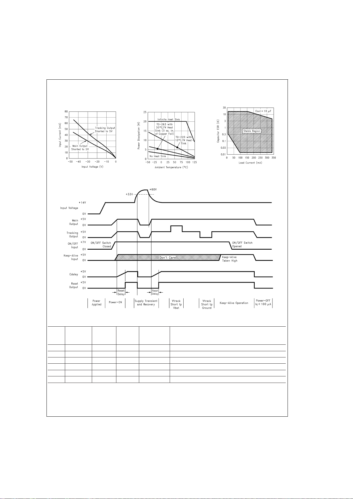
Operational Characteristics
Control Logic Truth Table
ON/OFF
Input
Keep-Alive
Input
Main
Output
Voltage
Tracking
Output
Voltage
Reset
Output
Operating Condition
L L 0V 0V 0V OFF, Input Current
<
100 µA
↑
L5V5V
↑
After Delay Outputs Turn ON, Power ON Delayed Reset
H X 5V 5V 5V Normal ON Condition
HX
<
4.45V
<
4.45V 0V Main Output Pulled Out of Regulation, Reset Flag Generated
↓
H 5V 5V 5V Keep-Alive, Continued Normal Operation
L
↑
5V 5V
↑
After Delay Outputs Turned ON by Keep-Alive Input
Reverse Battery
Input Current
DS012906-13
Maximum Power
Dissipation
DS012906-14
Output Capacitor ESR
DS012906-15
DS012906-16
LM9072
www.national.com5
 Loading...