

NSC LM8500IMT9, LM8500HLQ9 Datasheet
PRELIMINARY
LM8300/LM8400/LM8500
Four Wire Resistive Touchscreen Controller with
Brownout
General Description
The LM8300/8400/8500 is a 4-wire resistive touch screen
controller. The controller samples and drives the touch
screen without the need of any external hardware. The built
in 10-bit A/D provides a maximum of 500 coordinate pairs
per second (cpps). The data sampled from the touch screen
is sent out on the UART at a speed of 38400 bps.
The controller has a power-saving mode which causes the
controller to self-power down when no touch is detected on
the touch screen for a specified amount of time. In the
Devices included in this datasheet:
Device
LM8300 3, 5 V 2.7 to 2.9 V 3.27 MHz 18
LM8400 3, 5 V No Brownout 3.27 MHz 18
LM8500 5 V 4.17V to 4.5V 3.27, 10 MHz 18
Operating
Voltage
Brownout
Voltage
Operating
Frequency
self-power down mode, the current drawn is typically less
than 2 µA. The device resumes normal operation when a
touch is detected on the touch screen or communication is
detected on the UART. In addition to the self-power down
mode, the controller can be disabled by pulling the SHUTDOWN pin low. The controller resumes normal operation
when the SHUTDOWN pin is tristated or pulled high.
The controller has an internal non-volatile memory storage
element to store configuration data such as calibration points
or controller configurations.
I/O
Pins
Packages Temperature
44 LLP, 44 PLCC,
48 TSSOP
44 LLP, 44 PLCC,
48 TSSOP
44 LLP, 44 PLCC,
48 TSSOP
LM8300/LM8400/LM8500 Four Wire Resistive Touchscreen Controller with Brownout
October 2002
0˚C to +70˚C
0˚C to +70˚C
0˚C to +70˚C
Features
KEY FEATURES
n Supports 4 wire resistive touch panels
n Low power standby current typically less than 2 µA at
5.5V
n Maximum speed of 500 coordinate pairs per second
n Automatic wake up and return to standby
n 10 bit A/D
n On-chip touch screen current drivers - no external driver
required
n UART interface
n Controller configurations are stored in the internal
non-volatile storage element
n Touch pressure can be measured
APPLICATIONS
n Personal Digital Assistants
n Smart Hand-Held Devices
n Touch Screen Monitors
n Point-of-Sales Terminals
n KIOSK
n Pagers
n Cell Phones
COP8™is a trademark of National Semiconductor Corporation.
© 2002 National Semiconductor Corporation DS200372 www.national.com
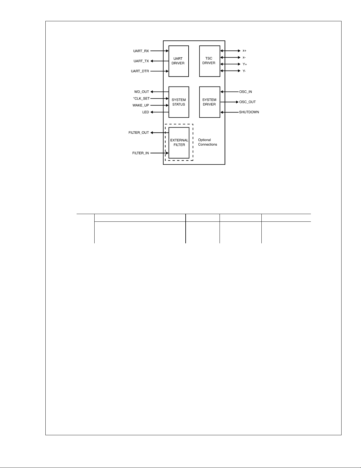
Block Diagram
LM8300/LM8400/LM8500
*
This pin is available in the LM8500. It is unused in the LM8300/LM8400.
Ordering Information
Part Numbering Scheme
LM 8300 H VA 9
Family and Feature Set Indicator No. Of Pins Package Type Temperature
8300 = Low Brownout Voltage
8400 = No Brownout
8500 = High Brownout Voltage
H=44Pin
I=48Pin
LQ = LLP
MT = TSSOP
VA = PLCC
20037201
9 = 0 to +70˚C
www.national.com 2

Table of Contents
General Description ............................................................................................................................................ 1
Features ............................................................................................................................................................. 1
Block Diagram .................................................................................................................................................... 2
Ordering Information .......................................................................................................................................... 2
Connection Diagrams ......................................................................................................................................... 4
2.0 Pin Descriptions ........................................................................................................................................... 5
Absolute Maximum Ratings ............................................................................................................................... 7
3.0 Electrical Characteristics .............................................................................................................................. 7
4.0 Functional Description .................................................................................................................................. 8
4.1 General ...................................................................................................................................................... 8
4.2 Advanced Pin Descriptions ....................................................................................................................... 8
4.3 USART Framing Format ............................................................................................................................ 9
4.3.1. Data packet format table .................................................................................................................... 9
4.3.2 Command Bytes .................................................................................................................................. 9
4.3.3 Advanced Command Bytes Descriptions .......................................................................................... 10
5.0 Oscillator .................................................................................................................................................... 12
6.0 Power Save Mode (Low Power Stand-by) ................................................................................................ 13
7.0 Averaging Algorithm ................................................................................................................................... 13
7.1 Delta Algorithm ........................................................................................................................................ 13
7.2 Focus Algorithm ....................................................................................................................................... 13
7.3 Communication Modes ............................................................................................................................ 14
8.0 Brownout Reset .......................................................................................................................................... 14
9.0 Calibration .................................................................................................................................................. 15
9.1 General Calibration Procedures .............................................................................................................. 17
9.2 Calibration Procedures with Coordinates Checking Enabled ................................................................. 18
9.3 Calibration Procedures with Coordinates Checking Disabled ................................................................ 18
Physical Dimensions ........................................................................................................................................ 19
LM8300/LM8400/LM8500
www.national.com3
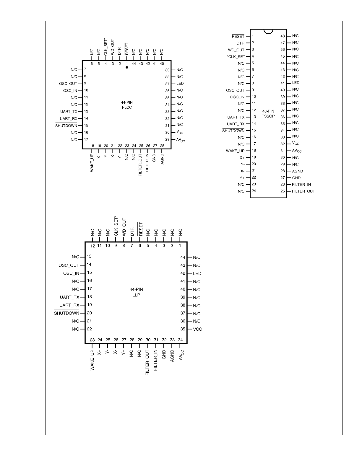
Connection Diagrams
LM8300/LM8400/LM8500
*
This pin is available in the LM8500. It is unused in the LM8300/LM8400.
20037202
Top View
Plastic Chip Package
See NS Package Number V44A
*
This pin is available in the LM8500. It is unused in the LM8300/LM8400.
20037204
Top View
TSSOP Package
See NS Package Number MTD48
*
This pin is available in the LM8500. It is unused in the LM8300/LM8400.
20037203
Top View
LLP Package
See NS Package Number LQA44A
www.national.com 4

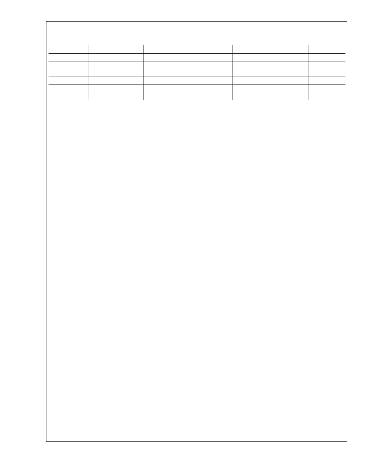
2.0 Pin Descriptions
Pinouts for 44- and 48-Pin Packages
Pin Name Direction Pin Description 44-Pin LLP 44-Pin PLCC 48-Pin TSSOP
RESET
DTR
WD_OUT
CLK_SET
Unused
Unused
Unused
Unused
1
2
2
2
2
OSC_OUT O Clock oscillator output 14 9 9
OSC_IN I Clock oscillator input 15 10 10
2
Unused
2
Unused
UART_TX O UART transmit pin (inverted for use
UART_RX I UART receive pin (inverted for use
SHUTDOWN I Shutdown pin, puts the device in halt
2
Unused
2
Unused
WAKE-UP I Used to wake up the processor from
X+ I/O Drives the X+ wire, also analog input
Y- I/O Drives the Y- wire, also analog input
X- I/O Drives the X- wire, also analog input
Y+ I/O Drives the Y+ wire, also analog input
2
Unused
2
Unused
FILTER_OUT O Analog output to the filter 30 25 25
FILTER_IN I Analog input from the filter 31 26 26
GND Digital ground 32 27 27
AGND Analog ground 33 28 28
AV
CC
V
CC
2
Unused
2
Unused
2
Unused
2
Unused
2
Unused
2
Unused
2
Unused
I Reset pin, pull low to reset 6 1 1
I
O
I
UART Data terminal ready signal, low
if not ready
Watchdog output, tie to RESET pin
for correct function
Used to set if crystal is 3.3 MHz (low)
or 10 MHz (floating or pulled high)
722
833
944
10 5 5
11 6 6
12 7 7
13 8 8
16 11 11
17 12 12
18 13 13
with standard RS-232 drivers)
19 14 14
with standard RS-232 drivers
20 15 15
mode if pulled low
21 16 16
22 17 17
23 18 18
halt mode with touch on touch screen
24 19 19
when sampling
25 20 20
when sampling
26 21 21
when sampling
27 22 22
when sampling
28 23 23
29 24 24
Analog power supply, connect to filter
34 29 31
for best performance
Digital power supply 35 30 32
XX33
XX34
36 31 35
37 32 36
38 33 37
39 34 38
40 35 39
LM8300/LM8400/LM8500
www.national.com5
2.0 Pin Descriptions (Continued)
Pinouts for 44- and 48-Pin Packages (Continued)
Pin Name Direction Pin Description 44-Pin LLP 44-Pin PLCC 48-Pin TSSOP
2
Unused
LED Output Optional LED output, low when
running, high in halt-mode
2
Unused
2
Unused
LM8300/LM8400/LM8500
2
Unused
Note 1: This is available in the LM8500 only.
Note 2: These pins are for future functional expansions.
41 36 40
42 37 41
34246
44347
54448
www.national.com 6
 Loading...