

NSC LM837N, LM837MX, LM837M Datasheet
LM837
Low Noise Quad Operational Amplifier
General Description
The LM837 is a quad operational amplifier designed for low
noise, high speed and wide bandwidth performance. It has a
new type of output stage which can drive a 600Ω load, making it ideal for almost all digital audio, graphic equalizer,
preamplifiers, and professional audio applications. Its high
performance characteristics also make it suitable for instrumentation applications where low noise is the key consideration.
The LM837 is internally compensated for unity gain operation. It is pin compatible with most other standard quad op
amps and can therefore be used to upgrade existing systems with little or no change.
Features
n High slew rate 10 V/µs (typ); 8 V/µs (min)
n Wide gain bandwidth product 25 MHz (typ); 15 MHz
(min)
n Power bandwidth 200 kHz (typ)
n High output current
±
40 mA
n Excellent output drive performance
>
600Ω
n Low input noise voltage 4.5 nV/
n Low total harmonic distortion 0.0015
%
n Low offset voltage 0.3 mV
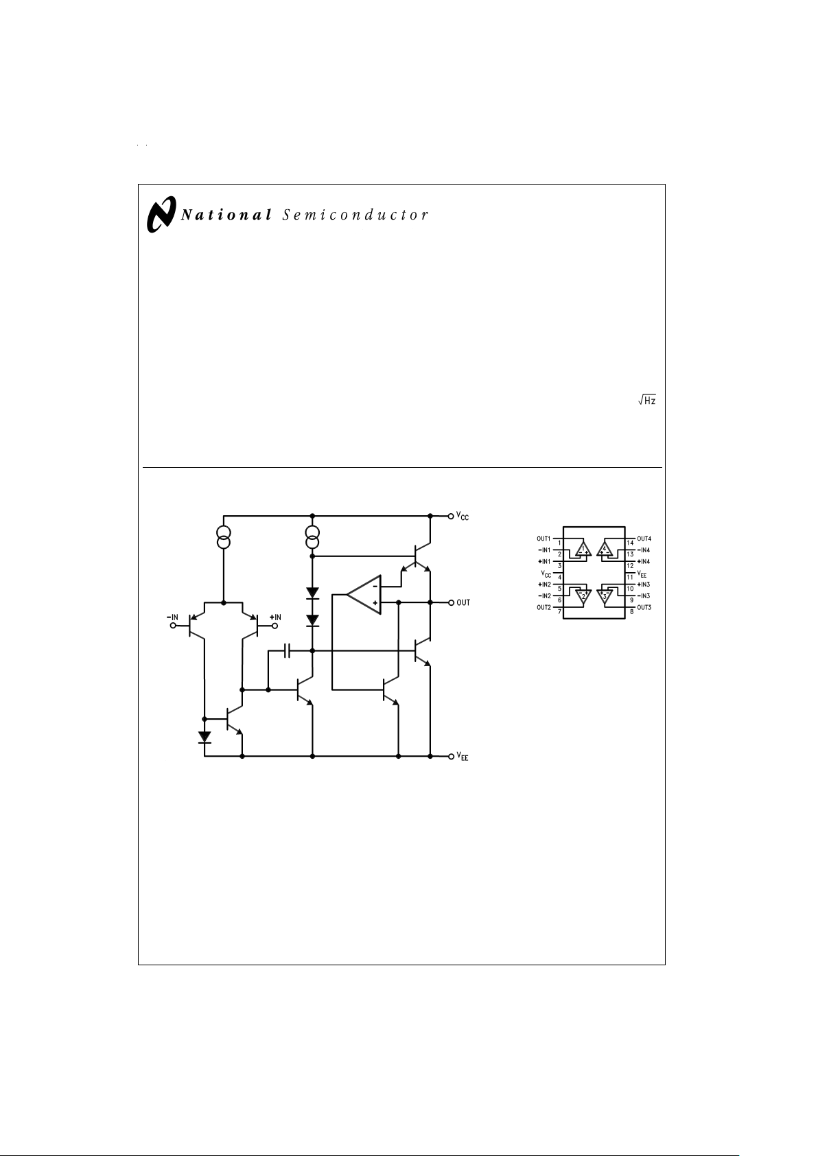
Schematic and Connection Diagrams
DS009047-1
Dual-In-Line Package
DS009047-2
Top View
Order Number LM837M
or LM837N
See NS Package Number
M14A or N14A
May 1999
LM837 Low Noise Quad Operational Amplifier
© 1999 National Semiconductor Corporation DS009047 www.national.com
Absolute Maximum Ratings (Note 1)
If Military/Aerospace specified devices are required,
please contact the National Semiconductor Sales Office/
Distributors for availability and specifications.
Supply Voltage, V
CC/VEE
±
18V
Differential Input Voltage, V
ID
(Note 2)
±
30V
Common Mode Input Voltage, V
IC
(Note 2)
±
15V
Power Dissipation, P
D
(Note 3) 1.2W (N)
830 mW (M)
Operating Temperature Range, T
OPR
−40˚C to +85˚C
Storage Temperature Range, T
STG
−60˚C to +150˚C
Soldering Information
Dual-In-Line Package
Soldering (10 seconds) 260˚C
Small Outline Package
Vapor Phase (60 seconds) 215˚C
Infrared (15 seconds) 220˚C
ESD rating to be determined.
See AN-450 “Surface Mounting Methods and Their Effect
on Product Reliability” for other methods of soldering
surface mount devices.
DC Electrical Characteristics
T
A
=
25˚C, V
S
=
±
15V
Symbol Parameter Condition Min Typ Max Units
V
OS
Input Offset Voltage R
S
=
50Ω 0.3 5 mV
I
OS
Input Offset Current 10 200 nA
I
B
Input Bias Current 500 1000 nA
A
V
Large Signal Voltage Gain R
L
=
2kΩ,V
OUT
=
±
10V 90 110 dB
V
OM
Output Voltage Swing R
L
=
2kΩ
±
12
±
13.5 V
R
L
=
600Ω
±
10
±
12.5 V
V
CM
Common Mode Input Voltage
±
12
±
14.0 V
CMRR Common Mode Rejection Ratio V
IN
=
±
12V 80 100 dB
PSRR Power Supply Rejection Ratio V
S
=
15
z
5, −15z−5 80 100 dB
I
S
Power Supply Current R
L
=
∞
, Four Amps 10 15 mA
AC Electrical Characteristics
T
A
=
25˚C, V
S
=
±
15V
Symbol Parameter Condition Min Typ Max Units
SR Slew Rate R
L
=
600Ω 8 10 V/µs
GBW Gain Bandwidth Product f=100 kHz, R
L
=
600Ω 15 25 MHz
Design Electrical Characteristics
T
A
=
25˚C, V
S
=
±
15V (Note 4)
Symbol Parameter Condition Min Typ Max Units
PBW Power Bandwidth V
O
=
25 V
P-P,RL
=
600Ω, THD
<
1
%
200 kHz
e
n1
Equivalent Input Noise Voltage JIS A, R
S
=
100Ω 0.5 µV
e
n2
Equivalent Input Noise Voltage f=1 kHz
4.5
nV/
i
n
Equivalent Input Noise Current f=1 kHz
0.7
pA/
THD Total Harmonic Distortion A
V
=
1, V
OUT
=
3 Vrms,
f=20
z
20 kHz, R
L
=
600Ω
0.0015
%
f
U
Zero Cross Frequency Open Loop 12 MHz
φ
m
Phase Margin Open Loop 45 deg
Input-Referred Crosstalk f=20
z
20 kHz −120 dB
∆V
OS
/∆T Average TC of Input Offset Voltage 2 µV/˚C
Note 1: Absolute Maximum Ratingsindicatelimits beyond which damage to the device may occur. Operating Ratings indicate conditions for which the device is functional, but do not guarantee specific performance limits. Electrical Characteristics state DC andAC electrical specifications under particular test conditions which guarantee specific performance limits. This assumes that the device is within the Operating Ratings. Specifications are not guaranteed for parameters where no limit is
given, however, the typical value is a good indication of device performance.
Note 2: Unless otherwise specified the absolute maximum input voltage is equal to the power supply voltage.
www.national.com 2
Design Electrical Characteristics (Continued)
Note 3: For operation at ambient temperatures above 25˚C, the device must be derated based on a 150˚C maximum junction temperature and a thermal resistance,
junction to ambient, as follows: LM837N, 90˚C/W; LM837M, 150˚C/W.
Note 4: The following parameters are not tested or guaranteed.
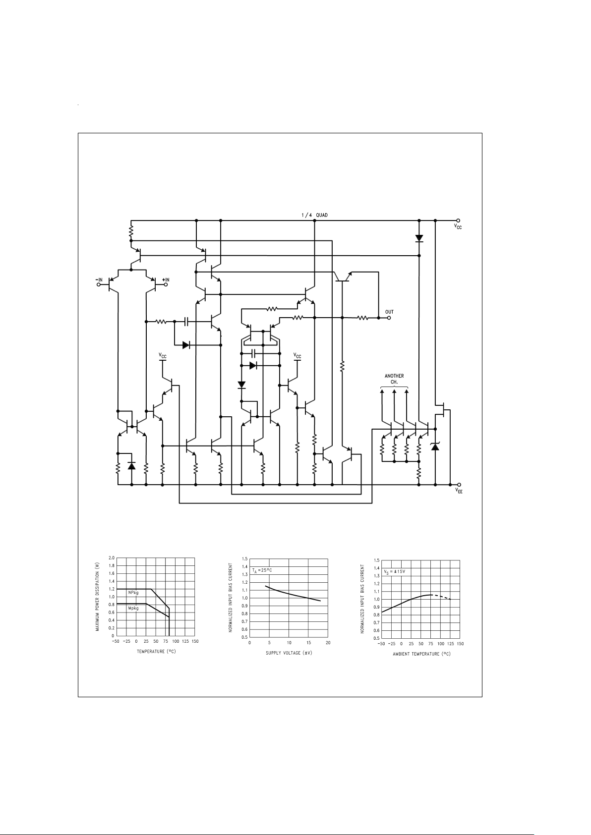
Detailed Schematic
Typical Performance Characteristics
DS009047-3
Maximum Power Dissipation vs
Ambient Temperature
DS009047-10
Normalized Input Bias Current
vs Supply Voltage
DS009047-11
Normalized Input Bias Current
vs Ambient Temperature
DS009047-12
www.national.com3
 Loading...