

NSC LM383A, LM383 Datasheet
LM383/LM383A
7W Audio Power Amplifier
March 1997
LM383/LM383A 7W Audio Power Amplifier
LM383/LM383A
General Description
The LM383 is a cost effective, high power amplifier suited for
automotive applications. High current capability (3.5A) enables the device to drive low impedance loads with low distortion. TheLM383iscurrentlimitedand thermally protected.
High voltage protection is available (LM383A) which enables
the amplifier to withstand 40V transients on its supply. The
LM383 comes in a 5-pin TO-220 package.
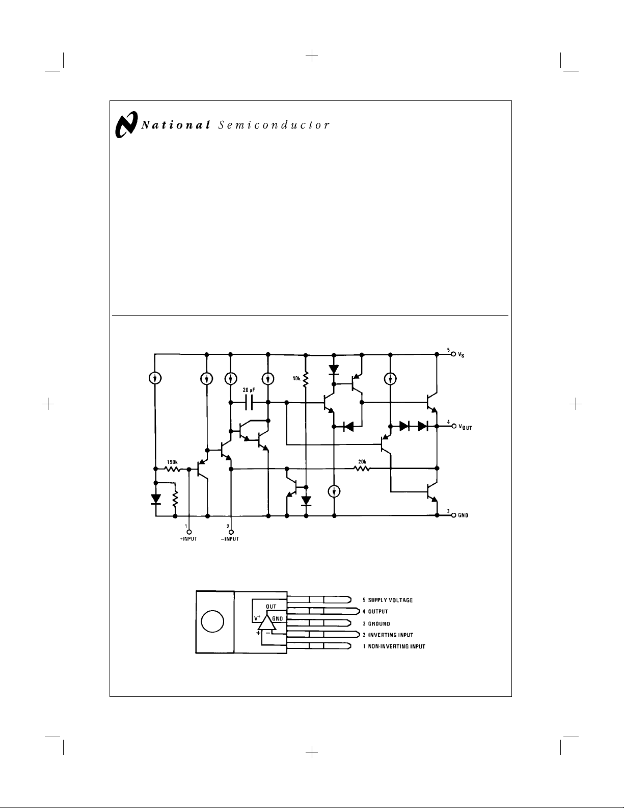
Equivalent Schematic
Features
n High peak current capability (3.5A)
n Large output voltage swing
n Externally programmable gain
n Wide supply voltage range (5V–20V)
n Few external parts required
n Low distortion
n High input impedance
n No turn-on transients
n High voltage protection available (LM383A)
n Low noise
n AC short circuit protected
Connection Diagram
Plastic Package
DS007145-2
Order Number LM383T or LM383AT
See NS Package Number T05D
© 1997 National Semiconductor Corporation DS007145 http:\\www.national.com
PrintDate=1997/04/01 PrintTime=11:52:16 7152 ds007145 Rev. No. 1
Proof 1
DS007145-1
1
Absolute Maximum Ratings (Note *NO
TARGET FOR FNXref NS0064*),
If Military/Aerospace specified devices are required,
please contact the National Semiconductor Sales Office/
Distributors for availability and specifications.
Peak Supply Voltage (50 ms)
LM383A (Note 2) 40V
LM383 25V
Repetitive 3.5A
Non-repetitive 4.5A
Input Voltage
±
Power Dissipation (Note 3) 15W
Operating Temperature 0˚C to +70˚C
Storage Temperature −60˚C to +150˚C
Lead Temperature
(Soldering, 10 sec.) 260˚C
Operating Supply Voltage 20V
Output Current
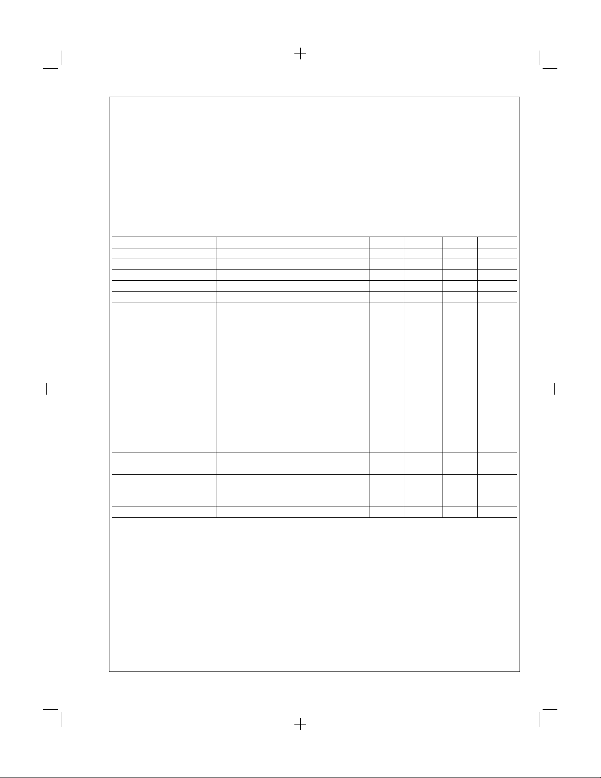
Electrical Characteristics
=
V
14.4V, T
S
Parameter Conditions Min Typ Max Units
DC Output Level 6.4 7.2 8 V
Quiescent Supply Current Excludes Current in Feedback Resistors 45 80 mA
Supply Voltage Range 5 20 V
Input Resistance 150 kΩ
Bandwidth Gain=40 dB 30 kHz
Output Power V
THD P
Ripple Rejection R
Input Noise Voltage R
Input Noise Current R
Note 1: A 0.2 µF capacitor in series with a 1Ω resistor should be placed as close as possible to pins 3 and 4 for stability.
Note 2: The LM383 shuts down above 25V.
Note 3: For operating at elevated temperatures, the device must be derated based on a 150˚C maximum junction temperature and a thermal resistance of 4˚C/W
junction to case.
TAB
=
25˚C, A
=
100 (40 dB), R
V
=
13.2V, f=1 kHz
S
=
R
4Ω, THD=10
L
=
R
2Ω, THD=10
L
=
V
13.8V, f=1 kHz
S
=
R
4Ω, THD=10
L
=
R
2Ω, THD=10
L
=
V
14.4V, f=1 kHz
S
=
R
4Ω, THD=10
L
=
R
2Ω, THD=10
L
=
R
1.6Ω, THD=10
L
=
V
16V, f=1 kHz
S
=
R
4Ω, THD=10
L
=
R
2Ω, THD=10
L
=
R
1.6Ω, THD=10
L
=
2W, R
o
P
o
S
R
S
S
S
L
=
4W, R
L
=
50Ω,f=100 Hz 30 40 dB
=
50Ω,f=1 kHz 44 dB
=
0, 15 kHz Bandwidth 2 µV
=
100 kΩ, 15 kHz Bandwidth 40 pA
=
4Ω, unless otherwise specified
L
%
%
%
%
%
%
4.8 5.5 W
7 8.6 W
%
%
%
%
=
4Ω,f=1 kHz 0.2
=
2Ω,f=1 kHz 0.2
4.7 W
7.2 W
5.1 W
7.8 W
9.3 W
7W
10.5 W
11 W
%
%
0.5V
http:\\www.national.com 2
PrintDate=1997/04/01 PrintTime=11:52:18 7152 ds007145 Rev. No. 1 Proof 2
 Loading...