

NSC LM337HVKSTEEL, LM337HVH Datasheet
LM137HV/LM337HV
3-Terminal Adjustable Negative Regulators
(High Voltage)
General Description
The LM137HV/LM337HV are adjustable 3-terminal negative
voltage regulators capable of supplying in excess of −1.5A
over an output voltage range of −1.2V to −47V. These regulators are exceptionally easy to apply, requiring only 2 external resistors to set the output voltage and 1 output capacitor
for frequencycompensation.The circuitdesign has been optimized for excellent regulation and low thermal transients.
Further, the LM137HV series features internal current limiting, thermal shutdown and safe-area compensation, making
them virtually blowout-proof against overloads.
The LM137HV/LM337HV serve a wide variety of applications including local on-card regulation,
programmable-output voltage regulation or precision current
regulation. The LM137HV/LM337HV are ideal complements
to the LM117HV/LM317HV adjustable positive regulators.
Features
n Output voltage adjustable from −1.2V to −47V
n 1.5A output current guaranteed, −55˚C to +150˚C
n Line regulation typically 0.01%/V
n Load regulation typically 0.3
%
n Excellent thermal regulation, 0.002%/W
n 77 dB ripple rejection
n Excellent rejection of thermal transients
n 50 ppm/˚C temperature coefficient
n Temperature-independent current limit
n Internal thermal overload protection
n P
+
Product Enhancement tested
n Standard 3-lead transistor package
n Output short circuit protected
Typical Applications
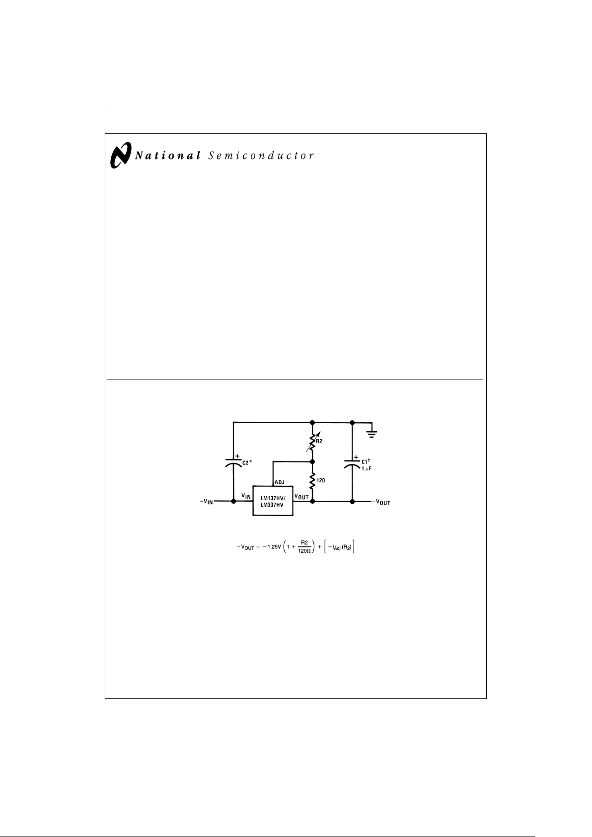
Adjustable Negative Voltage Regulator
DS009066-1
DS009066-25
†
C1=1 µF solid tantalum or 10 µF aluminum electrolytic required for stability.Output capacitors in the range of 1 µF to 1000 µF of aluminum or tantalum
electrolytic are commonly used to provide improved output impedance and rejection of transients.
*
C2=1 µF solid tantalum is required only if regulator is more than 4" from power-supply filter capacitor.
May 1999
LM137HV/LM337HV 3-Terminal Adjustable Negative Regulators (High Voltage)
© 1999 National Semiconductor Corporation DS009066 www.national.com
Absolute Maximum Ratings (Note 1)
If Military/Aerospace specified devices are required,
please contactthe National Semiconductor Sales Office/
Distributors for availability and specifications.
(Note 4)
Power Dissipation Internally limited
Input— Output Voltage Differential 50V
Operating Junction Temperature Range
LM137HV −55˚C to +150˚C
LM337HV 0˚C to +125˚C
Storage Temperature −65˚C to +150˚C
Lead Temperature
(Soldering, 10 sec.) 300˚
ESD rating is to be determined.
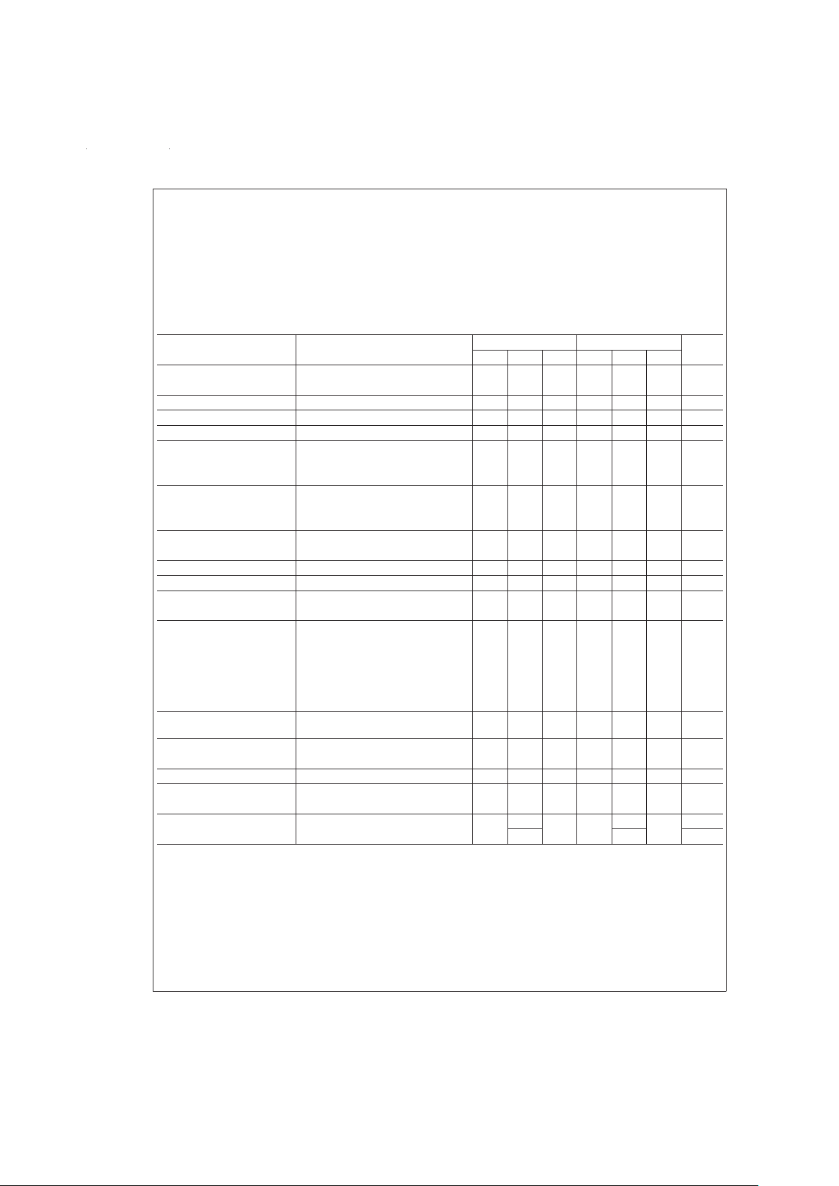
Electrical Characteristics (Note 2)
Parameter Conditions LM137HV LM337HV Units
Min Typ Max Min Typ Max
Line Regulation T
J
=
25˚C, 3V ≤ |V
IN−VOUT
| ≤ 50V, 0.01 0.02 0.01 0.04
%
/V
(Note 3) I
L
=
10 mA
Load Regulation T
J
=
25˚C, 10 mA ≤ I
OUT
≤ I
MAX
0.3 0.5 0.3 1.0
%
Thermal Regulation T
J
=
25˚C, 10 ms Pulse 0.002 0.02 0.003 0.04
%
/W
Adjustment Pin Current 65 100 65 100 µA
Adjustment Pin Current
Change
10 mA ≤ I
L
≤ I
MAX
25 25µA
3.0V ≤ |V
IN−VOUT
| ≤ 50V, 4 6 3 6 µA
T
J
=
25˚
Reference Voltage T
J
=
25˚C, (Note 4) −1.225 −1.250 −1.275 −1.213 −1.250 −1.287 V
3V ≤ |V
IN−VOUT
| ≤ 50V, (Note 4) −1.200 −1.250 −1.300 −1.200 −1.250 −1.300 V
10 mA ≤ I
OUT
≤ I
MAX
,P≤P
MAX
Line Regulation 3V ≤ |VIN−V
OUT
| ≤ 50V, (Note 3) 0.02 0.05 0.02 0.07
%
/V
I
L
=
10 mA
Load Regulation 10 mA ≤ I
OUT
≤ I
MAX
, (Note 3) 0.3 1 0.3 1.5
%
Temperature Stability T
MIN
≤ Tj≤ T
MAX
0.6 0.6
%
Minimum Load Current |V
IN−VOUT
| ≤ 50V 2.5 5 2.5 10 mA
|V
IN−VOUT
| ≤ 10V 1.2 3 1.5 6 mA
Current Limit |V
IN−VOUT
| ≤ 13V
K Package 1.5 2.2 3.2 1.5 2.2 3.5 A
H Package 0.5 0.8 1.6 0.5 0.8 1.8 A
|V
IN−VOUT
|=50V
K Package 0.2 0.4 0.8 0.1 0.4 0.8 A
H Package 0.1 0.17 0.5 0.050 0.17 0.5 A
RMS Output Noise,%of
V
OUT
T
J
=
25˚C, 10 Hz ≤ f ≤ 10 kHz 0.003 0.003
%
Ripple Rejection Ratio V
OUT
=
−10V, f=120 Hz 60 60 dB
C
ADJ
=
10 µF 66 77 66 77 dB
Long-Term Stability T
A
=
125˚C, 1000 Hours 0.3 1 0.3 1
%
Thermal Resistance, Junction H Package 12 15 12 15 ˚C/W
to Case K Package 2.3 3 2.3 3 ˚C/W
Thermal Resistance, Junction
to Ambient
H Package 140 140 ˚C/W
K Package 35 35 ˚C/W
Note 1: “Absolute Maximum Ratings” indicate limits beyond which damage to the device may occur. Operating Ratings indicate conditions for which the device is
functional, but do not guarantee specific performance limits.
Note 2: Unless otherwise specified, these specifications apply: −55˚C ≤ T
j
≤ +150˚C for the LM137HV, 0˚C ≤ Tj≤ +125˚C for the LM337HV; VIN−V
OUT
=
5V; and
I
OUT
=
0.1A for the TO-39 package and I
OUT
=
0.5A for the TO-3 package. Although power dissipation is internally limited, these specifications are applicable for
power dissipations of 2W for the TO-39 and 20W for the TO-3. I
MAX
is 1.5A for the TO-3 package and 0.2A for the TO-39 package.
Note 3: Regulation ismeasured at constantjunction temperature, usingpulse testing with a low duty cycle. Changes in output voltagedue to heatingeffects are covered under the specification for thermal regulations. Load regulation is measured on the output pin at a point
1
⁄8" below the base of the TO-3 and TO-39 packages.
Note 4: Refer to RETS137HVH drawing for LM137HVH or RETS137HVK for LM137HVK military specifications.
www.national.com 2
Electrical Characteristics (Note 2) (Continued)
DS009066-2
www.national.com3
 Loading...